EP0464496B1 - Méthode pour la synchronisation des déplacements simultanés des axes d'avance d'un tour - Google Patents
Méthode pour la synchronisation des déplacements simultanés des axes d'avance d'un tour Download PDFInfo
- Publication number
- EP0464496B1 EP0464496B1 EP91110184A EP91110184A EP0464496B1 EP 0464496 B1 EP0464496 B1 EP 0464496B1 EP 91110184 A EP91110184 A EP 91110184A EP 91110184 A EP91110184 A EP 91110184A EP 0464496 B1 EP0464496 B1 EP 0464496B1
- Authority
- EP
- European Patent Office
- Prior art keywords
- servo
- command data
- axis
- workpiece
- headstocks
- Prior art date
- Legal status (The legal status is an assumption and is not a legal conclusion. Google has not performed a legal analysis and makes no representation as to the accuracy of the status listed.)
- Expired - Lifetime
Links
Images


Classifications
-
- B—PERFORMING OPERATIONS; TRANSPORTING
- B23—MACHINE TOOLS; METAL-WORKING NOT OTHERWISE PROVIDED FOR
- B23B—TURNING; BORING
- B23B3/00—General-purpose turning-machines or devices, e.g. centre lathes with feed rod and lead screw; Sets of turning-machines
- B23B3/06—Turning-machines or devices characterised only by the special arrangement of constructional units
-
- G—PHYSICS
- G05—CONTROLLING; REGULATING
- G05B—CONTROL OR REGULATING SYSTEMS IN GENERAL; FUNCTIONAL ELEMENTS OF SUCH SYSTEMS; MONITORING OR TESTING ARRANGEMENTS FOR SUCH SYSTEMS OR ELEMENTS
- G05B19/00—Program-control systems
- G05B19/02—Program-control systems electric
- G05B19/18—Numerical control [NC], i.e. automatically operating machines, in particular machine tools, e.g. in a manufacturing environment, so as to execute positioning, movement or co-ordinated operations by means of program data in numerical form
- G05B19/416—Numerical control [NC], i.e. automatically operating machines, in particular machine tools, e.g. in a manufacturing environment, so as to execute positioning, movement or co-ordinated operations by means of program data in numerical form characterised by control of velocity, acceleration or deceleration
-
- G—PHYSICS
- G05—CONTROLLING; REGULATING
- G05B—CONTROL OR REGULATING SYSTEMS IN GENERAL; FUNCTIONAL ELEMENTS OF SUCH SYSTEMS; MONITORING OR TESTING ARRANGEMENTS FOR SUCH SYSTEMS OR ELEMENTS
- G05B2219/00—Program-control systems
- G05B2219/30—Nc systems
- G05B2219/42—Servomotor, servo controller kind till VSS
- G05B2219/42186—Leader-follower, motion proportional to axis
-
- G—PHYSICS
- G05—CONTROLLING; REGULATING
- G05B—CONTROL OR REGULATING SYSTEMS IN GENERAL; FUNCTIONAL ELEMENTS OF SUCH SYSTEMS; MONITORING OR TESTING ARRANGEMENTS FOR SUCH SYSTEMS OR ELEMENTS
- G05B2219/00—Program-control systems
- G05B2219/30—Nc systems
- G05B2219/45—Nc applications
- G05B2219/45125—Four axis, spindle lathe
-
- G—PHYSICS
- G05—CONTROLLING; REGULATING
- G05B—CONTROL OR REGULATING SYSTEMS IN GENERAL; FUNCTIONAL ELEMENTS OF SUCH SYSTEMS; MONITORING OR TESTING ARRANGEMENTS FOR SUCH SYSTEMS OR ELEMENTS
- G05B2219/00—Program-control systems
- G05B2219/30—Nc systems
- G05B2219/50—Machine tool, machine tool null till machine tool work handling
- G05B2219/50216—Synchronize speed and position of several axis, spindles
-
- Y—GENERAL TAGGING OF NEW TECHNOLOGICAL DEVELOPMENTS; GENERAL TAGGING OF CROSS-SECTIONAL TECHNOLOGIES SPANNING OVER SEVERAL SECTIONS OF THE IPC; TECHNICAL SUBJECTS COVERED BY FORMER USPC CROSS-REFERENCE ART COLLECTIONS [XRACs] AND DIGESTS
- Y10—TECHNICAL SUBJECTS COVERED BY FORMER USPC
- Y10T—TECHNICAL SUBJECTS COVERED BY FORMER US CLASSIFICATION
- Y10T82/00—Turning
- Y10T82/10—Process of turning
-
- Y—GENERAL TAGGING OF NEW TECHNOLOGICAL DEVELOPMENTS; GENERAL TAGGING OF CROSS-SECTIONAL TECHNOLOGIES SPANNING OVER SEVERAL SECTIONS OF THE IPC; TECHNICAL SUBJECTS COVERED BY FORMER USPC CROSS-REFERENCE ART COLLECTIONS [XRACs] AND DIGESTS
- Y10—TECHNICAL SUBJECTS COVERED BY FORMER USPC
- Y10T—TECHNICAL SUBJECTS COVERED BY FORMER US CLASSIFICATION
- Y10T82/00—Turning
- Y10T82/25—Lathe
- Y10T82/2502—Lathe with program control
-
- Y—GENERAL TAGGING OF NEW TECHNOLOGICAL DEVELOPMENTS; GENERAL TAGGING OF CROSS-SECTIONAL TECHNOLOGIES SPANNING OVER SEVERAL SECTIONS OF THE IPC; TECHNICAL SUBJECTS COVERED BY FORMER USPC CROSS-REFERENCE ART COLLECTIONS [XRACs] AND DIGESTS
- Y10—TECHNICAL SUBJECTS COVERED BY FORMER USPC
- Y10T—TECHNICAL SUBJECTS COVERED BY FORMER US CLASSIFICATION
- Y10T82/00—Turning
- Y10T82/25—Lathe
- Y10T82/2552—Headstock
Definitions
- the present invention relates to a device and a method for synchronously interlocking the feed axes of a lathe. More specifically, the present invention relates to synchronously interlocking the feed of the lathe by synchronously interlocking the feed axes of the lathe, wherein the lathe is equipped with first and second feed axes for driving two opposed headstocks.
- a spindle synchronizing system is disclosed in Patent Abstracts of Japan, Vol. 13, No. 555 (M-904) [3903], December 11, 1989 and JP-A-1 228 752.
- the system comprises a lathe having two opposed spindles and is controlled by calculating a command value for a slave spindle based on a feed-back value of torque.
- Each spindle is driven by a servo-motor through a servomotor amplifier connected to a computerized numerical control (CNC).
- CNC computerized numerical control
- the system is designed to remove torque differences which arise in different drive motor characteristics and different servoamplifier characteristics of the two spindle drive mechanisms.
- Another lathe is known in the art which turns a long workpiece chucked by two opposed headstocks which are driven synchronously.
- Fig. 6 shows a configuration of such a lathe, wherein a tool rest 1 is coupled to a cutting tool 2 and a ballscrew 3 for driving the same.
- An X-axis servo motor 4 is coupled to the ballscrew 3 for driving the same and coupled to a workpiece 5 that is to be turned.
- a chuck 11 for gripping one end of the workpiece 5, a headstock 12 mounted with a spindle, a ballscrew 13 coupled to said headstock 12 for driving the same, and a z-axis servo motor 14 coupled to said ballscrew 13 for driving the same are also shown.
- Elements 21 to 24 form a unit identical to elements 11 to 14, respectively, and, therefore, their functions are identical to those discussed above.
- the prior art lathe causes the workpiece 5 to be gripped at both ends by the headstocks 12, 22 which are then interlocked synchronously to turn the workpiece 5.
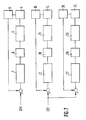
- Fig. 7 is a block diagram of servo amplifiers in a numerical controller (NC) (not shown) for controlling the lathe shown in Fig. 6. Specifically, an X-axis servo motor 4 for driving the headstock 1, a position sensor 6 for detecting the position of said headstock 1, and a known error counter 7 for detecting the error of a position sensor 6 are shown. A digital-to-analog converter 8 for converting the value of the error counter 7 into an analog value and a power amplifier 9 for amplifying said analog value and driving the servo motor 4 are also shown.
- NC numerical controller
- Elements 16 to 19 and 26 to 29 are individually designed to be of the same configuration as elements 6 to 9 and drive the Z1-axis servo motor 14 and the Z2-axis servo motor 24, respectively.
- the X-axis position command pulse Cpx is given by the NC (not shown) for driving servo motor 4.
- a z-axis position command pulse Cpz is given by the NC for driving the two servo motors 14 and 24 simultaneously.
- Fig. 6 the movements in the X-axis direction of the tool rest 1 and the Z-axis direction of the headstocks 12, 22 are directed by a machining program stored in the NC memory (not shown).
- the desired movement in the X and Z directions are written for execution on a block basis, e.g. N001 G01x100.Z200.F2. or N002 G00Z-50. and operated on by a central processing block (not shown) comprising a CPU, memory, etc., contained in the NC.
- the desired movement is converted into the position command pulse trains of the corresponding axes by a known pulse distributor.
- the position command pulse trains are Cpx and Cpz shown in Fig. 7, wherein Cpx is output for the X axis and Cpz for the Z axis.
- the position command pulse train Cpx is added to the value of the error counter 7, a difference between that value and the position sensor 6 value is provided to the power amplifier 9 via the digital-to-analog converter 8, which drives the servo motor 4 at a commanded speed in a direction correcting the error value.
- the tool rest 1 is moved in the X axis direction accordingly.
- the position command pulse Cpz is processed in a similar manner. However, because Cpz is given to both error counters 17 and 27, the two headstocks 12 and 22 (Fig. 6) are operated synchronously.
- Figs. 8(a) and 8(b) show the machine and workpiece under the influence of displacements, wherein the full lines indicate the machine and workpiece before the displacements develop and the broken lines (5a, 10a) indicate the situation after the displacements have developed.
- the displacements are compensated for by a deformed workpiece, which occurs when the rigidity of the workpiece is lower than that of the machine and servo.
- the displacements are compensated for by a deformed machine when the rigidity of the machine is lower than those of the workpiece and servo.
- the rigidity of the servo may be lower than those of the workpiece and machine. In this case, the motor torque is saturated to disable control and therefore an overload alarm is activated to stop the motor or drive amplifier. In any of the above instances, excessive force is applied to the workpiece, resulting in reduced turning accuracy.
- the feed axes of a lathe having first and a second feed axes for driving two opposed headstocks are linked via a workpiece to achieve synchronous interlocking control of the two feed axes.
- the present method compensates for the positions of the feed axes by means of position offset values of the feed axes calculated from the displacement of the machine or workpiece.
- the displacements are detected in accordance with a difference between the torques of the two feed axes to be controlled for synchronous interlocking.
- the displacement of the machine or workpiece is compensated for by moving the headstocks, which are synchronized in the corrected positions unless a new displacement is detected.
- Fig. 1 is an overall block diagram of a lathe in accordance with one embodiment of the present invention.
- Fig. 2 is a flowchart illustrating the method of obtaining offset values from a torque difference according to an embodiment of the present invention.
- Fig. 3 is a block diagram illustrating the apparatus for implementing the method of Fig. 2.
- Fig. 4 is a flowchart illustrating the operation of an embodiment of the present invention.
- Fig. 5 illustrates torque waveforms of the servo motors.
- Fig. 6 is a configuration diagram showing a lathe employing a synchronous interlocking operation.
- Fig. 7 is a block diagram showing a drive system for achieving the synchronous operation known in the art.
- Figs. 8(a) and 8(b) illustrate how the workpiece and machine are distorted by displacements in the known synchronous control.
- a machine or workpiece displacement is detected by way of a torque difference detected between the two servo motors controlling the feed axes. This displacement is compensated for by the movement of the headstocks driven from the servo motors by an excess distance corresponding to the detected displacement.
- FIG. 5 illustrates the method for which the machine or workpiece displacement can be detected by way of the detected servo motor torques.
- a graph 40 represents the command pulse Cpz described in Fig. 7 in terms of speed.
- a torque curve 41 of a master axis shows the change in accordance with the speed command indicated by the graph 40, and torque curve 42 of a slave axis indicates its changes under similar conditions.
- Graphs 43 and 44 indicate the torque curves of the master and slave axes in this state.
- a difference 45 between the torque curves 43 and 44, i.e., the torque difference 45 may be assumed to be a torque consumed as a reaction against the action of the machine or workpiece displacement and can be used to detect the machine or workpiece displacement. The magnitude of this torque difference can determine the machine or workpiece displacement.
- Fig. 1 shows an embodiment of the present invention, wherein a workpiece 5, which is gripped at both ends by chucks 11 and 21, is coupled to two headstocks 12 and 22, respectively.
- a ballscrew is coupled to the servo motor 14 for driving the headstock 12, and a ballscrew 23 is coupled to the servo motor 24 for driving the headstock 22 in a similar manner.
- the servo motor 14 is coupled to a position and speed detecting pulse coder 15 and the servo motor 24 to a position and speed detecting pulse coder 25.
- the servo motor 14 is driven by a servo amplifier 30 and the servo motor 24 by a servo amplifier 31.
- each of the servo amplifiers 30, 31 comprises a controller having a CPU, memory, etc. and a power amplifier having a power transistor, etc.
- the controller controls positions and speeds in accordance with feedback signals from the pulse coders 15, 25 and position command data from NC 32.
- the NC 32 provides the master axis servo amplifier 30 with position command data Cpz only and provides the slave axis servo amplifier 31 with command data which is the sum of the position command data Cpz and offset position command data Cof.
- the offset position command data Cof is calculated from a torque difference between the servo motors 14 and 24.
- the currents of the servo motors 14 and 24 are converted into digital values via analog-to-digital converters 33 and 34, respectively, and the results are fed back to the NC 32.
- These feedback signals are multiplied by an appropriate constant for conversion into units of distance, then differentiated to obtain the variation of distance, and compensated for by defining a delay with an appropriate time constant.
- the delay eliminates a temporary torque variation attributable to the fluctuation of drive motor characteristics due to the transient response of the motor and fetches the variation generated constantly.
- the time constant (T), error value (E) for providing the rated output, and rated torque (tmax) are given as parameters.
- the occurrence of displacement causes the headstock 22 driven from the servo motor 24 or the headstock 12 driven from the servo motor 14 to move by an excess (compensation) distance corresponding to that displacement. Therefore, the deformation of the workpiece or machine as shown in Fig. 8 will not take place, the headstocks will be synchronized together at the offset positions unless displacement is newly detected, and the servo motors will be driven at the same torque.
- Fig. 2 is a flowchart of software processing for finding the offset values from the torque difference.
- the numeric values following S indicate processing step numbers.
- Fig. 3 is a block diagram of an NC implementing the above S1 to S7 processing steps.
- Fig. 4 is a flowchart illustrating the operation of the present invention.
- G198 indicates an interlocking mode command in the machining program which uses the Z1 axis as the master axis
- G199 an interlocking mode command in the machining program which employs the Z2 axis as the master axis
- G197 an interlocking mode canceling command in the machining program.
- the error value (E) and rated torque (tmax) for providing the rated output used above to determine the offset value need not be this data but may be certain constants obtained by experiment.
- the above embodiment assumes that the servo motors and servo amplifiers are identical in characteristics and a failure in synchronous interlocking does not occur due to differences in these characteristics. If there are differences in these characteristics and a failure in synchronous interlocking occurs, synchronization technology disclosed in Japanese Patent Publication No. 228752 of 1989 may be employed for the synchronous control of the servo motors.
- This publication discloses technology, which calculates offset values of spindle motors from spindle motor torques, rotating positions and speeds if there are differences in motor characteristics and a failure in synchronous interlocking occurs when the same command is given to two spindle motors, in order to prevent a failure in synchronous interlocking, thereby protecting a workpiece from twist.
- the present invention may be used to prevent the reduction of machining accuracy due to displacement, and the spindle synchronism technology disclosed in Japanese Patent Publication No. 228752/1989 may be employed for the synchronous control of the servo motors to prevent the reduction of machining accuracy due to differences in motor characteristics.
- any torque difference in excess of a predetermined valve may trigger an alarm without causing compensation. This is because the displacement has become so excessive that the machining accuracy may be adversely affected by the compensating movement of the headstocks.
- the machining accuracy of a workpiece on a lathe having the performance of two machines is improved by preventing any unnecessary load from being applied to the workpiece due to the displacement of the machine or the workpiece itself when one workpiece is gripped simultaneously by two chucks. Since the servo motors are free from unnecessary loads, their power consumption can be reduced, resulting in energy savings. In addition, the machine itself remains free of distortion so that machine accuracy can be guaranteed for a long period of time.
Landscapes
- Engineering & Computer Science (AREA)
- Human Computer Interaction (AREA)
- Manufacturing & Machinery (AREA)
- Physics & Mathematics (AREA)
- General Physics & Mathematics (AREA)
- Automation & Control Theory (AREA)
- Mechanical Engineering (AREA)
- Numerical Control (AREA)
- Control Of Position Or Direction (AREA)
- Turning (AREA)
Claims (4)
- Procédé de commande de verrouillage réciproque synchrone d'un tour comprenant deux poupées opposées (12, 22) ayant une pièce à usiner serrée entre elles, les poupées (12, 22) étant positionnées le long respectivement de premier et second axes d'avance (Z1, Z2) à une distance de séparation (1e), ledit procédé comprenant les étapes de :a) déterminer une différence de couple entre deux servomoteurs (14, 24) pour commander les deux poupées (12, 22) le long desdits premier et second axes d'avance (Z1, Z2);
caractérisé parb) déterminer, sur la base de la différence de couple, une valeur de décalage (pe) de la distance de séparation des poupées (1e), ladite valeur de décalage représentant un déplacement de machine ou de pièce à usiner dans la direction axiale des axes d'avancement (Z1, Z2);c) fournir une donnée de commande de position de décalage (Cof) sur la base de ladite valeur de décalage (pe) à au moins l'un des deux servomoteurs, déplaçant de la sorte au moins l'une desdites poupées (12, 22) pour compenser ledit déplacement axial. - Procédé de commande de verrouillage réciproque synchrone de la revendication 1, dans lequel le premier (Z1) ou le second (Z2) axe d'avancement est défini comme un axe maître, où l'autre est défini comme un axe esclave, où ledit axe esclave reçoit la donnée de commande de position de décalage précitée (Cof) pour compensation de déplacement axial.
- Procédé de commande de verrouillage réciproque synchrone de la revendication 1, dans lequel les axes d'avancement précité (Z1, Z2) sont seulement compensés dans un mode de verrouillage réciproque et les valeurs de décalage (pe) sont supprimées lorsque le mode de verrouillage réciproque est réinitialisé.
- Dispositif pour commande de verrouillage réciproque synchrone d'un tour comprenant :deux poupées opposées (12, 22) ayant une pièce à usiner fixée entre elles, les poupées étant individuellement couplées à des vis à billes (13, 23) pour se déplacer le long respectivement de premier et second axes d'avancement (Z1, Z2);où chaque vis à billes (13, 23) est couplée à un servomoteur (14, 24) pour entraîner lesdites poupées (12, 22) selon une donnée de commande de position;un codeur d'impulsion de détection de position et de vitesse (15, 25) relié à chaque servomoteur;un amplificateur de servomoteur (30, 31) pour commander chaque servomoteur (14, 24), chaque servo amplificateur étant relié à une commande numérique informatisée (CNC; 32), où un servo amplificateur fonctionne comme un servo amplificateur d'axe maître tandis que l'autre fonctionne comme un servo amplificateur d'axe esclave;
caractérisé en ce quela CNC (32) fournit le servo amplificateur d'axe maître en donnée de commande de position (Cpz) seulement et fournit le servo amplificateur d'axe esclave en donnée de commande qui est la somme de la donnée de commande de position (Cpz) et la donnée de commande de position de décalage (Cof), cette dernière étant calculée à partir d'une différence de couple entre les servomoteurs (14, 24);où la différence de couple est déterminée à partir des courants desdits servomoteurs (14, 24) convertis en valeurs numériques par l'intermédiaire de convertisseurs analogique-numérique (33, 34) et réinjectés à la CNC (32); etoù lors de la réception de ladite donnée de commande, les servomoteurs déplacent les poupées (12, 22) pour compenser un déplacement axial de la pièce à usiner.
Applications Claiming Priority (2)
| Application Number | Priority Date | Filing Date | Title |
|---|---|---|---|
| JP2177865A JP2518457B2 (ja) | 1990-07-05 | 1990-07-05 | 施盤の送り軸同期連動方法 |
| JP177865/90 | 1990-07-05 |
Publications (3)
| Publication Number | Publication Date |
|---|---|
| EP0464496A2 EP0464496A2 (fr) | 1992-01-08 |
| EP0464496A3 EP0464496A3 (en) | 1992-06-10 |
| EP0464496B1 true EP0464496B1 (fr) | 1996-03-13 |
Family
ID=16038427
Family Applications (1)
| Application Number | Title | Priority Date | Filing Date |
|---|---|---|---|
| EP91110184A Expired - Lifetime EP0464496B1 (fr) | 1990-07-05 | 1991-06-20 | Méthode pour la synchronisation des déplacements simultanés des axes d'avance d'un tour |
Country Status (4)
| Country | Link |
|---|---|
| US (1) | US5181441A (fr) |
| EP (1) | EP0464496B1 (fr) |
| JP (1) | JP2518457B2 (fr) |
| DE (1) | DE69117820T2 (fr) |
Families Citing this family (24)
| Publication number | Priority date | Publication date | Assignee | Title |
|---|---|---|---|---|
| JP3259371B2 (ja) * | 1992-11-17 | 2002-02-25 | 三菱電機株式会社 | 工作機械のワーク保持方法及びその装置 |
| US6122998A (en) * | 1993-06-29 | 2000-09-26 | Fanuc, Ltd. | Force control method for a bar feeder of a lathe |
| KR950008007A (ko) * | 1993-09-07 | 1995-04-15 | 수우 에이 그리핀 | 공작물을 기계가공하도록 회전시키는 장치 및 기계 가공에 의한 제품 형성 방법 |
| JP3595357B2 (ja) * | 1994-06-30 | 2004-12-02 | ファナック株式会社 | ディジタルサーボによるタンデム制御方法 |
| JP3369005B2 (ja) * | 1994-09-19 | 2003-01-20 | 正二 湯山 | 薬剤の容量分割装置 |
| WO1999001252A1 (fr) * | 1997-07-02 | 1999-01-14 | Mitsubishi Denki Kabushiki Kaisha | Dispositif de commande de synchronisation pour servomoteurs |
| WO1999044108A1 (fr) * | 1998-02-27 | 1999-09-02 | Mitsubishi Denki Kabushiki Kaisha | Controleur de synchronisation |
| JP4346824B2 (ja) | 1998-12-24 | 2009-10-21 | 三菱電機株式会社 | 数値制御装置 |
| US7148635B1 (en) * | 2005-09-21 | 2006-12-12 | Rockwell Automation Technologies, Inc. | Motor drive with synchronized timing |
| KR20030075805A (ko) * | 2002-03-20 | 2003-09-26 | 화천기공 주식회사 | 다두선반 |
| JP3923047B2 (ja) * | 2003-03-04 | 2007-05-30 | ファナック株式会社 | 同期制御装置 |
| CN1299174C (zh) * | 2003-09-27 | 2007-02-07 | 哈尔滨工业大学 | 电机控制装置 |
| JP4070744B2 (ja) * | 2004-04-28 | 2008-04-02 | ファナック株式会社 | 同期制御装置 |
| JP2005322076A (ja) * | 2004-05-10 | 2005-11-17 | Fanuc Ltd | 数値制御装置 |
| JP4361071B2 (ja) | 2005-07-08 | 2009-11-11 | ファナック株式会社 | サーボ制御装置 |
| JP2008225533A (ja) * | 2007-03-08 | 2008-09-25 | Fanuc Ltd | サーボ制御装置 |
| JP5855840B2 (ja) * | 2011-03-23 | 2016-02-09 | 中村留精密工業株式会社 | 2主軸対向nc旋盤及び防振加工方法 |
| JP5073126B1 (ja) * | 2011-03-31 | 2012-11-14 | コマツNtc株式会社 | クランクシャフトミラー及びクランクシャフトの製造方法 |
| CN102274981B (zh) * | 2011-07-13 | 2013-06-05 | 黄山市继林机械制造有限公司 | 一种双工位圆棒加工机床 |
| JP5842276B2 (ja) * | 2012-02-28 | 2016-01-13 | 株式会社ダイフク | 物品移載装置 |
| JP6683748B2 (ja) * | 2018-02-23 | 2020-04-22 | ファナック株式会社 | 数値制御装置 |
| JP7323758B2 (ja) * | 2018-11-22 | 2023-08-09 | スター精密株式会社 | 旋盤 |
| JP2021037589A (ja) * | 2019-09-03 | 2021-03-11 | シチズン時計株式会社 | 工作機械および工作機械の制御装置 |
| JP7723257B2 (ja) * | 2021-08-10 | 2025-08-14 | スター精密株式会社 | 旋盤、及び、その突っ切りバイト破損検出方法 |
Family Cites Families (11)
| Publication number | Priority date | Publication date | Assignee | Title |
|---|---|---|---|---|
| DE422651C (de) * | 1922-07-28 | 1925-12-09 | Otto Rutenbeck | Maschine zum Kopieren von Schuhleisten und aehnlichen Gegenstaenden |
| JPS58120449A (ja) * | 1981-12-29 | 1983-07-18 | Fanuc Ltd | 工作機械のテ−ブル制御方式 |
| SU1073003A1 (ru) * | 1982-05-17 | 1984-02-15 | Белорусский Ордена Трудового Красного Знамени Политехнический Институт | Устройство дл токарной обработки нежестких деталей |
| DE8530182U1 (de) * | 1985-10-24 | 1990-06-21 | Wadell Equipment Co., Inc., Edison, N.J. | Anpassungsfähiges Bearbeitungssystem |
| JPS6439101A (en) * | 1987-01-26 | 1989-02-09 | Nec Corp | Reflector antenna |
| US4949444A (en) * | 1987-04-17 | 1990-08-21 | Yamazaki Mazak Corporation | Machine tool machining method |
| JPS649602A (en) * | 1987-07-01 | 1989-01-12 | Kao Corp | Ferromagnetic metal powder and manufacture thereof |
| JPH01228751A (ja) * | 1988-03-09 | 1989-09-12 | Fanuc Ltd | 2つの主軸を有する工作機械 |
| JPH01228752A (ja) * | 1988-03-10 | 1989-09-12 | Fanuc Ltd | 主軸同期方式 |
| JPH01246045A (ja) * | 1988-03-28 | 1989-10-02 | Yamazaki Mazak Corp | 工作機械における加工座標系の設定制御方法 |
| DE3933993C1 (fr) * | 1989-10-11 | 1991-02-07 | Gildemeister Automation Gmbh, 3000 Hannover, De |
-
1990
- 1990-07-05 JP JP2177865A patent/JP2518457B2/ja not_active Expired - Fee Related
-
1991
- 1991-06-20 EP EP91110184A patent/EP0464496B1/fr not_active Expired - Lifetime
- 1991-06-20 DE DE69117820T patent/DE69117820T2/de not_active Expired - Fee Related
- 1991-07-03 US US07/725,118 patent/US5181441A/en not_active Expired - Lifetime
Also Published As
| Publication number | Publication date |
|---|---|
| EP0464496A3 (en) | 1992-06-10 |
| DE69117820D1 (de) | 1996-04-18 |
| JPH0465701A (ja) | 1992-03-02 |
| JP2518457B2 (ja) | 1996-07-24 |
| US5181441A (en) | 1993-01-26 |
| HK1007013A1 (en) | 1999-03-26 |
| DE69117820T2 (de) | 1996-10-31 |
| EP0464496A2 (fr) | 1992-01-08 |
Similar Documents
| Publication | Publication Date | Title |
|---|---|---|
| EP0464496B1 (fr) | Méthode pour la synchronisation des déplacements simultanés des axes d'avance d'un tour | |
| EP1742128B1 (fr) | Servocontrôleur | |
| EP0598386B1 (fr) | Méthode et appareil de commande pour maintenir une pièce sur une machine-outil | |
| JP3755054B2 (ja) | 同期制御装置 | |
| EP0557530A1 (fr) | Dispositif de commande numerique | |
| HK1004347B (en) | Control apparatus and method for holding a workpiece in a machine tool | |
| EP0268887B1 (fr) | Commande numérique d'avancement pour une machine-outil | |
| US5175680A (en) | Synchronizing control apparatus | |
| WO2000039646A1 (fr) | Dispositif de commande numerique | |
| JPWO1999044108A1 (ja) | 同期制御装置 | |
| US5027680A (en) | Machine tool with two spindles | |
| US5212648A (en) | Method and apparatus for machining a non-circular workpiece | |
| JPH01228752A (ja) | 主軸同期方式 | |
| JPH0649260B2 (ja) | 同期制御装置 | |
| HK1007013B (en) | Method for synchronously interlocking feed axes of a lathe | |
| JPH03190601A (ja) | ワーク交換方法 | |
| US5270941A (en) | Numerical control apparatus with superimposing control function | |
| JP3308656B2 (ja) | サーボモータの制御方法 | |
| JPH05318283A (ja) | 工具たわみ補正方式 | |
| JP2788725B2 (ja) | 数値制御装置 | |
| JPH0716803B2 (ja) | 対向型2軸スピンドル旋盤のワーク授受確認方法とその制御装置 | |
| JPH02241392A (ja) | 同期制御装置 | |
| JP2654228B2 (ja) | 数値制御装置 | |
| JPH0319725A (ja) | 数値制御装置のネジ切り方式 | |
| JPH01188914A (ja) | 数値制御機械の二重ループ制御装置 |
Legal Events
| Date | Code | Title | Description |
|---|---|---|---|
| PUAI | Public reference made under article 153(3) epc to a published international application that has entered the european phase |
Free format text: ORIGINAL CODE: 0009012 |
|
| AK | Designated contracting states |
Kind code of ref document: A2 Designated state(s): DE GB |
|
| PUAL | Search report despatched |
Free format text: ORIGINAL CODE: 0009013 |
|
| AK | Designated contracting states |
Kind code of ref document: A3 Designated state(s): DE GB |
|
| 17P | Request for examination filed |
Effective date: 19920811 |
|
| 17Q | First examination report despatched |
Effective date: 19940919 |
|
| GRAH | Despatch of communication of intention to grant a patent |
Free format text: ORIGINAL CODE: EPIDOS IGRA |
|
| GRAA | (expected) grant |
Free format text: ORIGINAL CODE: 0009210 |
|
| AK | Designated contracting states |
Kind code of ref document: B1 Designated state(s): DE GB |
|
| REF | Corresponds to: |
Ref document number: 69117820 Country of ref document: DE Date of ref document: 19960418 |
|
| REG | Reference to a national code |
Ref country code: GB Ref legal event code: 727 |
|
| REG | Reference to a national code |
Ref country code: GB Ref legal event code: 727A |
|
| REG | Reference to a national code |
Ref country code: GB Ref legal event code: 727B |
|
| REG | Reference to a national code |
Ref country code: GB Ref legal event code: SP |
|
| PLBE | No opposition filed within time limit |
Free format text: ORIGINAL CODE: 0009261 |
|
| STAA | Information on the status of an ep patent application or granted ep patent |
Free format text: STATUS: NO OPPOSITION FILED WITHIN TIME LIMIT |
|
| 26N | No opposition filed | ||
| REG | Reference to a national code |
Ref country code: GB Ref legal event code: 746 Effective date: 19971202 |
|
| PGFP | Annual fee paid to national office [announced via postgrant information from national office to epo] |
Ref country code: GB Payment date: 19980611 Year of fee payment: 8 |
|
| PG25 | Lapsed in a contracting state [announced via postgrant information from national office to epo] |
Ref country code: GB Free format text: LAPSE BECAUSE OF NON-PAYMENT OF DUE FEES Effective date: 19990620 |
|
| GBPC | Gb: european patent ceased through non-payment of renewal fee |
Effective date: 19990620 |
|
| PGFP | Annual fee paid to national office [announced via postgrant information from national office to epo] |
Ref country code: DE Payment date: 20010611 Year of fee payment: 11 |
|
| PG25 | Lapsed in a contracting state [announced via postgrant information from national office to epo] |
Ref country code: DE Free format text: LAPSE BECAUSE OF NON-PAYMENT OF DUE FEES Effective date: 20030101 |