EP0464592A2 - Détecteur de données - Google Patents
Détecteur de données Download PDFInfo
- Publication number
- EP0464592A2 EP0464592A2 EP91110466A EP91110466A EP0464592A2 EP 0464592 A2 EP0464592 A2 EP 0464592A2 EP 91110466 A EP91110466 A EP 91110466A EP 91110466 A EP91110466 A EP 91110466A EP 0464592 A2 EP0464592 A2 EP 0464592A2
- Authority
- EP
- European Patent Office
- Prior art keywords
- counter
- order bit
- bit
- output
- high order
- Prior art date
- Legal status (The legal status is an assumption and is not a legal conclusion. Google has not performed a legal analysis and makes no representation as to the accuracy of the status listed.)
- Ceased
Links
Images

Classifications
-
- H—ELECTRICITY
- H03—ELECTRONIC CIRCUITRY
- H03K—PULSE TECHNIQUE
- H03K21/00—Details of pulse counters or frequency dividers
- H03K21/08—Output circuits
- H03K21/12—Output circuits with parallel read-out
Definitions
- the present invention relates to a data detector for a counter.
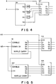
- synchronous counters having a 4-bit output such as TTL 74LS169 and D flip-flops having a common clock such as TTL 74LS373 are usually used, as shown in Fig. 5, in which numeral 65 denotes a clock signal, numeral 66 denotes a latch signal, numerals 63 and 64 denote D flip-flops, and numerals 61 and 62 denote synchronous counters having a 4-bit output.
- a common clock is used for lower order and higher order synchronous counters 61 and 62, and a carry signal of the lower order counter 61 is used as an enable signal to the higher order counter 62.
- next clock is inputted before the high order bit is enabled. Therefore, it is not counted by the higher order counter and the carry to the high order bit is not effected.
- an asynchronous counter an input to one bit is an output from the immediately lower order bit. Accordingly, the high order bit is produced after the low order bit but no malfunction occurs unless a maximum frequency of the counter is exceeded.
- the asynchronous counter if data of the counter is detected in the course of carry from the low order bit to the high order bit, the data prior to the carry of the high order bit is detected.
- a counter having a plural-bit output means for compensating a low order bit/high order bit output time shift of the counter caused in carrying over from a low order bit to a high order bit of the counter, and means for detecting low order bit/high order bit data of the counter compensated by the compensation means, are provided to produce correct data even for a high speed clock.
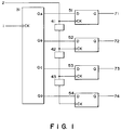
- Fig. 1 shows one embodiment of the present invention.
- Numeral 1 denotes a clock signal
- numeral 2 denotes a latch signal
- numeral 31 denotes an asynchronous counter having a 4-bit output such as TTL 74LS93
- numerals 41 to 43 denote delay lines for compensating delays in the bits of the counter 31
- numerals 51 to 54 denote D flip-flops such as TTL 74LS74 for latching the output of the counter 31.
- Fig. 2 shows a timing chart for the circuit of Fig. 1. When the latch signal is applied at a time t0, the output of the D flip-flops does not represent a correct count "1011" at the time to but it represents "1111” unless the delay lines 41 to 43 are inserted.
- the delay times of the delay lines 41 to 43 are equal to differences of the output times between Q A and Q B , Q B and Q C , and Q C and Q D of the counter 31, the outputs of the D flip-flops 51 to 54 are delayed by the delay times so that the correct data is always outputted. (In the present embodiment, "1011")
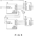
- Fig. 3 shows another embodiment of the present invention.
- Numeral 11 denotes an up-clock signal
- numeral 12 denotes a down-clock signal
- numeral 3 denotes a latch signal
- numerals 32 and 33 denote partial synchronous counters having a 4-bit output such as 74LS193
- numerals 55 and 56 denote D flip-flops such as 74LS173.
- the partial synchronous counters 32 and 33 are in synchronism within the IC's but there is a time difference (a time difference from the application of an up/down-clock signal to the generation of a carry/borrow signal) between the outputs of the low order counter 32 and the high order counter 33 because the clock is transmitted through gates between the counters 32 and 33.
- a delay line 44 having the same delay time as the time difference is inserted to the clock (latch signal) of the D flip-flop 56.
- the counters 32 and 33 produce correct data.
- Fig. 4 shows a further embodiment of the present invention.
- Numeral 4 denotes a clock signal
- numeral 5 denotes a latch signal
- numeral 34 denotes an asynchronous counter having a 4-bit output such as 74LS93
- numerals 45 to 47 denote delay lines for compensating timings of the bit outputs of the counter 34
- numeral 57 denotes a D flip-flop such as 74LS173.
- the delay times of the delay lines 45 to 47 are selected to compensate the differences of the output times between Q D and Q A , Q D and Q B , and Q D and Q C .
- the counter 34 operates like a synchronous counter and correct data is outputted by simultaneously latching the bit data. The same applies when the partially synchronous counter is used.
- the delay lines are used to delay the signals, although any devices which delay in time may be used.
- the high speed and high capacity counting is attained.
- a 32-bit counter is constructed by a fully synchronous type FAST-TTL counter IC (74F169)
- the countable frequency is 13.2 MHz while it is extended up to 80 MHz when it is implemented by a partially synchronous type FAST-TTL counter IC (74F193).
- the counter having plural-bit output, means for compensating a shift of output times of the low bit and the high order bit of the counter caused by the carry signal from low order bit to the high order bit of the counter, and means for detecting the low and high order bit data of the counter compensated by the compensation means, are provided to attain the high speed counting.
- a data detector comprises a counter having a plural-bit parallel output, compensation means for compensating a shift of output times of a low order bit and a high order bit of the counter caused by a carry signal from the low order bit to the high order bit, and detection means for detecting data of the low order bit and the high order bit of the counter compensated by the compensation means.
Landscapes
- Synchronisation In Digital Transmission Systems (AREA)
Applications Claiming Priority (2)
| Application Number | Priority Date | Filing Date | Title |
|---|---|---|---|
| JP2171588A JPH0461420A (ja) | 1990-06-28 | 1990-06-28 | データ検出装置 |
| JP171588/90 | 1990-06-28 |
Publications (2)
| Publication Number | Publication Date |
|---|---|
| EP0464592A2 true EP0464592A2 (fr) | 1992-01-08 |
| EP0464592A3 EP0464592A3 (en) | 1992-03-11 |
Family
ID=15925943
Family Applications (1)
| Application Number | Title | Priority Date | Filing Date |
|---|---|---|---|
| EP19910110466 Ceased EP0464592A3 (en) | 1990-06-28 | 1991-06-25 | Data detector |
Country Status (3)
| Country | Link |
|---|---|
| US (1) | US5187725A (fr) |
| EP (1) | EP0464592A3 (fr) |
| JP (1) | JPH0461420A (fr) |
Cited By (2)
| Publication number | Priority date | Publication date | Assignee | Title |
|---|---|---|---|---|
| GB2271232A (en) * | 1992-10-03 | 1994-04-06 | Motorola Inc | Pulse generation/sensing arrangement for use in a microprocessor system |
| WO2010042764A1 (fr) * | 2008-10-08 | 2010-04-15 | Qualcomm Incorporated | Compteur asynchrone à faible puissance et procédé |
Families Citing this family (5)
| Publication number | Priority date | Publication date | Assignee | Title |
|---|---|---|---|---|
| JP3759026B2 (ja) | 2001-12-06 | 2006-03-22 | セイコーエプソン株式会社 | 半導体装置およびその検査方法ならびに電子機器 |
| US7758582B2 (en) * | 2002-06-14 | 2010-07-20 | Smith & Nephew, Inc. | Device and methods for placing external fixation elements |
| JP2005157883A (ja) * | 2003-11-27 | 2005-06-16 | Oki Electric Ind Co Ltd | リセット回路 |
| JP5040427B2 (ja) * | 2007-05-11 | 2012-10-03 | ソニー株式会社 | データ処理方法、データ処理装置、固体撮像装置、撮像装置、電子機器 |
| KR102664062B1 (ko) * | 2019-05-30 | 2024-05-14 | 삼성전자주식회사 | 비동기 카운터와 동기 카운터를 포함하는 코드 생성기 및 그것의 동작 방법 |
Family Cites Families (11)
| Publication number | Priority date | Publication date | Assignee | Title |
|---|---|---|---|---|
| US2956181A (en) * | 1959-01-07 | 1960-10-11 | Sperry Rand Corp | Parallel fast carry counter with serial carry gate propagation |
| US3108228A (en) * | 1961-12-18 | 1963-10-22 | Ibm | Delay compensation by distributed synchronous pulses |
| US3631350A (en) * | 1970-09-15 | 1971-12-28 | Collins Radio Co | Synchronous counting apparatus |
| US4519091A (en) * | 1983-08-03 | 1985-05-21 | Hewlett-Packard Company | Data capture in an uninterrupted counter |
| US4789959A (en) * | 1985-03-05 | 1988-12-06 | Intersil, Inc. | Delay circuit for a real time clock |
| JPS6258725A (ja) * | 1985-09-06 | 1987-03-14 | Mitsubishi Electric Corp | カウンタ回路 |
| JPH06105285B2 (ja) * | 1986-08-22 | 1994-12-21 | 三菱電機株式会社 | 半導体集積回路装置 |
| US4881248A (en) * | 1986-08-28 | 1989-11-14 | Nec Corporation | Counter circuit provided with means for reading out counted data by read-command signal applied asynchronously with clock signals to be counted |
| US4796095A (en) * | 1986-09-09 | 1989-01-03 | Rioch Company, Limited | Method of generating image scanning clock signals in optical scanning apparatus |
| US5062126A (en) * | 1990-03-26 | 1991-10-29 | Hughes Aircraft Company | High speed synchronous counter system and process with look-ahead carry generating circuit |
| US5060243A (en) * | 1990-05-29 | 1991-10-22 | Motorola, Inc. | Ripple counter with reverse-propagated zero detection |
-
1990
- 1990-06-28 JP JP2171588A patent/JPH0461420A/ja active Pending
-
1991
- 1991-06-12 US US07/714,031 patent/US5187725A/en not_active Expired - Fee Related
- 1991-06-25 EP EP19910110466 patent/EP0464592A3/en not_active Ceased
Cited By (7)
| Publication number | Priority date | Publication date | Assignee | Title |
|---|---|---|---|---|
| GB2271232A (en) * | 1992-10-03 | 1994-04-06 | Motorola Inc | Pulse generation/sensing arrangement for use in a microprocessor system |
| GB2271232B (en) * | 1992-10-03 | 1997-05-07 | Motorola Inc | Pulse generation/sensing arrangement for use in a microprocessor system |
| US5631592A (en) * | 1992-10-03 | 1997-05-20 | Motorola, Inc. | Pulse generation/sensing arrangement for use in a microprocessor system |
| WO2010042764A1 (fr) * | 2008-10-08 | 2010-04-15 | Qualcomm Incorporated | Compteur asynchrone à faible puissance et procédé |
| US7864915B2 (en) | 2008-10-08 | 2011-01-04 | Qualcomm Incorporated | Low-power asynchronous counter and method |
| CN102171929A (zh) * | 2008-10-08 | 2011-08-31 | 高通股份有限公司 | 低功率异步计数器及方法 |
| CN102171929B (zh) * | 2008-10-08 | 2014-04-02 | 高通股份有限公司 | 低功率异步计数器及方法 |
Also Published As
| Publication number | Publication date |
|---|---|
| JPH0461420A (ja) | 1992-02-27 |
| US5187725A (en) | 1993-02-16 |
| EP0464592A3 (en) | 1992-03-11 |
Similar Documents
| Publication | Publication Date | Title |
|---|---|---|
| US5600824A (en) | Clock generating means for generating bus clock and chip clock synchronously having frequency ratio of N-1/N responsive to synchronization signal for inhibiting data transfer | |
| US10782344B2 (en) | Technique for determining performance characteristics of electronic devices and systems | |
| US4463443A (en) | Data buffer apparatus between subsystems which operate at differing or varying data rates | |
| EP0133735B1 (fr) | Dispositif de compteur à N-bits | |
| KR910013272A (ko) | 2개의 비동기 포인터들 사이의 비교차와 프로그래값들 사이의 측정차를 결정하기 위한 방법 및 장치 | |
| IL144674A (en) | Dynamic wave interface device and methods | |
| US5291529A (en) | Handshake synchronization system | |
| US5142556A (en) | Data transfer system and method of transferring data | |
| EP0464592A2 (fr) | Détecteur de données | |
| CN100446456C (zh) | 发送时钟信号相位与接收时钟信号相位锁相的系统及方法 | |
| KR920007349A (ko) | 디지틀 펄스 처리장치 | |
| US5566343A (en) | Serial data transfer apparatus for determining a reception time and a transmission time | |
| US5790891A (en) | Synchronizing unit having two registers serially connected to one clocked elements and a latch unit for alternately activating the registers in accordance to clock signals | |
| US20010013802A1 (en) | System and process for high speed interface clock skew correction | |
| US4380736A (en) | Peripheral interface adapter circuit for counter synchronization | |
| US5651014A (en) | Rate generator circuit for semiconductor test system | |
| EP0628913A1 (fr) | Circuit de détection des signaux d'interruption | |
| EP0530030B1 (fr) | Circuit pour la détection d'un signal de synchronisation lors de la transmission de données avec synchronisation de trâme | |
| KR100617999B1 (ko) | 메모리 장치 내의 데이터 캡처를 위한 방법 및 장치 | |
| US4789959A (en) | Delay circuit for a real time clock | |
| US5249154A (en) | Data access controller and method | |
| KR200158764Y1 (ko) | 동기식 직렬 수신 장치 | |
| JPH04354219A (ja) | データ伝送方式 | |
| US6181730B1 (en) | Pull-in circuit for pseudo-random pattern | |
| JP3013767B2 (ja) | フレームタイミング位相調整回路 |
Legal Events
| Date | Code | Title | Description |
|---|---|---|---|
| PUAI | Public reference made under article 153(3) epc to a published international application that has entered the european phase |
Free format text: ORIGINAL CODE: 0009012 |
|
| AK | Designated contracting states |
Kind code of ref document: A2 Designated state(s): DE FR GB IT NL |
|
| PUAL | Search report despatched |
Free format text: ORIGINAL CODE: 0009013 |
|
| AK | Designated contracting states |
Kind code of ref document: A3 Designated state(s): DE FR GB IT NL |
|
| 17P | Request for examination filed |
Effective date: 19920724 |
|
| 17Q | First examination report despatched |
Effective date: 19950321 |
|
| STAA | Information on the status of an ep patent application or granted ep patent |
Free format text: STATUS: THE APPLICATION HAS BEEN REFUSED |
|
| 18R | Application refused |
Effective date: 19960405 |