EP0464646A2 - Plattenantriebsgerät - Google Patents
Plattenantriebsgerät Download PDFInfo
- Publication number
- EP0464646A2 EP0464646A2 EP91110580A EP91110580A EP0464646A2 EP 0464646 A2 EP0464646 A2 EP 0464646A2 EP 91110580 A EP91110580 A EP 91110580A EP 91110580 A EP91110580 A EP 91110580A EP 0464646 A2 EP0464646 A2 EP 0464646A2
- Authority
- EP
- European Patent Office
- Prior art keywords
- counter
- spindle motor
- signal
- output
- disk
- Prior art date
- Legal status (The legal status is an assumption and is not a legal conclusion. Google has not performed a legal analysis and makes no representation as to the accuracy of the status listed.)
- Granted
Links
Images



Classifications
-
- G—PHYSICS
- G11—INFORMATION STORAGE
- G11B—INFORMATION STORAGE BASED ON RELATIVE MOVEMENT BETWEEN RECORD CARRIER AND TRANSDUCER
- G11B15/00—Driving, starting or stopping record carriers of filamentary or web form; Driving both such record carriers and heads; Guiding such record carriers or containers therefor; Control thereof; Control of operating function
-
- G—PHYSICS
- G11—INFORMATION STORAGE
- G11B—INFORMATION STORAGE BASED ON RELATIVE MOVEMENT BETWEEN RECORD CARRIER AND TRANSDUCER
- G11B19/00—Driving, starting, stopping record carriers not specifically of filamentary or web form, or of supports therefor; Control thereof; Control of operating function ; Driving both disc and head
- G11B19/20—Driving; Starting; Stopping; Control thereof
- G11B19/28—Speed controlling, regulating, or indicating
Definitions
- the present invention relates to a disk drive apparatus and, more particularly, to a disk drive apparatus employing a sector servo method.
- a servo control of a spindle motor which is used in a hard disk drive apparatus has been executed on the basis of a detection of an output of a Hall element or a detection of a back electromotive force of a coil of a motor.
- a pulse signal which is intermittently derived every sector can be used as an FG.
- the magnetic head is located in a landing zone on the magnetic disk surface for a leading period of the rotation of the spindle motor, so that there is a problem such that a servo control cannot be executed.
- an object of the invention to provide a disk drive apparatus in which servo controls before and after a rising time point of the rotation of a spindle motor can be executed by a common master clock and a common circuit.
- a disk drive apparatus for reproducing information signal from a disk on which the information signal is recorded, and servo sector pulse is recorded at predetermined intervals in a direction of rotation, comprising, a spindle motor for driving rotatably the disk, means for detecting a rotation of the spindle motor and for generating a detection output, means for reproducing the sector pulse from the disk, means for switching the detection output and the sector pulses, a counter for counting a reference clock signal, sampling means for sampling an output of the counter by an output signal of the switching means, generating means for detecting a difference between continuous sampling values contained in an output of the sampling means and for generating a speed control signal, motor control means for controlling the spindle motor using the speed control signal, and control means for controlling the switching means responsive to a rotational speed of the disk so that switching means selects the detection output when the rotational speed is slow and selects the sector pulse when the rotational speed is nearly equal to a normal speed.
- a hard disk drive apparatus is described as an example of a disk drive apparatus.
- Fig. 1 denotes a magnetic disk.
- the servo zones ZS are radially formed on a magnetic disk 1 at equal angle intervals as shown in Fig. 2.
- the data zones ZD are formed among the servo zones ZS.
- a servo signal is reproduced only in the case where a magnetic head 3 is located over the servo zone ZS.
- a control operation of the magnetic head 3 is executed on the basis of the servo signals which are intermittently obtained from the servo zones ZS.
- a reproduction output from the magnetic head 3 is supplied to a servo zone detecting circuit 5 through a head amplifier 4.
- the servo zone detecting circuit 5 detects whether the magnetic head 3 has been located in the servo zone ZS or not on the basis of the reproduction output from the magnetic head 3.
- a servo sector pulse PSS is supplied to a terminal 6b of a switch 6 from the servo zone detecting circuit 5.
- a spindle motor 7 for rotating the magnetic disk 1 is provided under the magnetic disk 1.
- a DC motor of three phases is used as a spindle motor 7.
- a back electromotive force pulse PIW are supplied to a terminal 6a of the switch 6 from the spindle motor 7.
- a Hall element can be provided for detecting rotational phase of the spindle motor 7, and Hall pulse from the Hall element can be used instead of the pulse PIW.
- a master clock signal (simply referred to as a clock signal hereinbelow) CLX which is supplied through a terminal 8 is sent to a counter 9.
- the counter 9 is, for example, a free-run counter of 24 bits and a counting operation of the clock signal CLK mentioned above is always performed.
- Count values X as incremental values which are formed by the counting operation of the clock signals CLK are obtained.
- the counter 9 is used for a measurement of a rotational speed upon rising of the rotation of the spindle motor 7 and can assure a measuring accuracy in a stationary rotation.
- Data is extracted from the counter 9 on an 8-bit unit basis of upper eight bits, middle eight bits, and lower eight bits, respectively.
- the upper 8-bit data is supplied to a terminal 10a of a switch 10.
- the lower 8-bit data is supplied to a terminal 11b of a switch 11.
- the middle 8-bit data excluding the upper and lower 8-bit data is supplied to terminals 10b and 11a of the switches 10 and 11, respectively.
- the switches 10 and 11 mentioned above are connected to a capture register 12.
- a terminal 10c of the switch 10 is connected to a register 13 of the upper eight bits of the capture register 12.
- a terminal 11c of the switch 11 is connected to a register 14 of the lower eight bits of the capture register 12.
- the switches 6, 10 and 11 are controlled by a selection signal SE which is supplied through a terminal 15 from a controller (not shown).
- the selection signal SE is set to, for example, the low level ("0") until the rotation of the spindle motor 7 sufficiently rises.
- the selection signal SE is set to, for example, the high level (“1") after the rotation of the spindle motor 7 sufficiently rose and the stationary rotation was derived and the servo sector pulses PSS was stably obtained.
- the switches 6, 10, and 11 are constructed in a manner such that, for example, when the signal SE is at the low level (“0"), terminals 6a and 6c, 10a and 10c, and 11a and 11c are connected and that when it is at the high level (“1"), terminals 6b and 6c, 10b and 10c and 11b and 11c are connected.
- the back electromotive force pulse PIW is supplied as a capture trigger to the capture register 12 until the rotation of the spindle motor 7 sufficiently rises.
- Data of upper and middle sixteen bits of the counter 9 is taken into the capture register 12 in parallel at a timing when the back electromotive force pulse PIW is supplied and the 16-bit data is supplied to a CPU 16 through the capture register 12.
- the servo sector pulse PSS which is supplied from the servo zone detecting circuit 5 is sent as a capture trigger to the capture register 12.
- the middle and lower 16-bit data of the counter 9 is taken into the capture register 12 in parallel at a timing when the servo sector pulse PSS is supplied and the 16-bit data is supplied to the CPU 16 through the capture register 12.
- an interval of about (1/10) of the pulse interval of the back electromotive force pulses PIW is set to a pulse interval of the servo sector pulses PSS.
- the CPU 16 detects a period of the capture trigger by using the count values X as a 16-bit data mentioned above and a reference count value Xs.
- a correcting process of the count value X is executed and, thereafter, the comparison between the difference of the count values X and the reference counter value Xs is performed.
- the reference count value Xs is changed in accordance with the kind and interval of the capture triggers which are supplied.
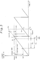
- Fig. 3 shows a state in the case where an axis of ordinate denotes the count value X of the counter 9 and an axis of abscissa indicates a time t.
- an alternate long and short dash line denotes a countable maximum count value Xmax.
- the count values do not overflow at the stages of points A and B as timing at which the capture trigger is supplied, so that there is no need to perform the correcting process.
- a difference Xn (XB - XA) between the count values of the points A and B is obtained.
- the difference Xn corresponds to an interval Tn at which the capture trigger is supplied.
- a reference interval Ts derived from a reference rotational speed corresponds to the reference count value Xs. Therefore, a difference between the reference count value Xs and the difference Xn between the above count values is obtained as a servo error ER1.
- the error ER1 mentioned above is converted into an analog error signal SER by a D/A converter 17 and is supplied to a driving circuit 18.
- the driving circuit 18 controls the rotational speed on the basis of the error signal SER in a manner such that the rotational speed of the spindle motor 7 is set to a value near the reference rotational speed.
- an overflow flag register (referred to as a flag register hereinbelow) 19 is set.
- a signal S1 indicative of the occurrence of the overflow is supplied to the CPU 16.
- the CPU 16 executes the correcting process of the count value X which is supplied from the capture register 12 and, thereafter, the CPU 16 supplies a signal S2 to the flag register 19 and resets the flag register 19.
- the operation corresponds to that a triangle CDE is upwardly moved in parallel, a vertex D of the triangle CDE is overlaid on a point F, and a triangle BCOEO is formed, thereby obtaining the difference X(n + 1) between the count values in an interval T(n + 1) is obtained by using the sampling point B as a reference.
- the difference X(n + 1) between the count values corresponds to the interval T(n + 1) at which the capture trigger is supplied.
- the error ER1 as a servo error amount is obtained and converted into the error signal SER.
- a step in which the rotational speed of the spindle motor 7 is controlled on the basis of the error signal SER is similar to that in the foregoing case of the interval Tn at which the capture trigger is supplied. Therefore, the overlapped explanations are omitted.
- the interval at which the count value X of the counter 9 is sampled becomes sequentially short in accordance with an increase in rotational speed of the spindle motor 7 when the rotation of the spindle motor 7 rises. Therefore, the count value X also sequentially decreases.
- the reference count value Xs is set to be constant. Therefore, when the rotation of the spindle motor 7 rises, a level of the error signal SER increases and a control voltage of a relatively high level is added to the spindle motor 7. The level of the error signal SER also decreases as the rotational speed of the spindle motor 7 increases and the control voltage which is applied to the spindle motor 7 gradually decreases.
- the invention is not limited to the above example.
- the interval can be also changed, for example, in correspondence to change in period of the back electromotive force pulse PIW or sector pulse PSS.
- the count values X are sampled by the back electromotive force pulse PIW obtained from the spindle motor 7.
- the count values X are sampled by the servo sector pulse PSS in a state in which the rotation of the spindle motor 7 has sufficiently risen and the stationary rotation has been derived and the servo sector pulses PSS is stably obtained.
- the differences Xn and X(n + 1) of the count values corresponding to the intervals at which the capture trigger is supplied are obtained.
- the rotational speed of the spindle motor 7 is controlled on the basis of the error ER1 which is formed from the differences Xn and X(n + 1) of the count values and the reference count value Xs.
- a coarse servo control based on the rotation detection output of the spindle motor which is executed when the rotation of the spindle motor 7 rises and a high precision servo control based on the reproduction output of the sector pulse which is performed after the rotation of the spindle motor became a stable state can be executed by a common master block and a common circuit.
- a range of the data in the counter 9 of 24 bits which is used depends on the pulse interval to be measured and a resolution of the counter 9 and can be arbitrarily selected in accordance with the specifications.
- middle and lower 16-bit data of the counter 9 is used in the case of measuring the period of the servo sector pulse PSS and upper and middle 16-bit data is used in the case of measuring the period of the back electromotive force pulse PIW. Consequently, it means that the interval of the back electromotive force pulse PIW is equal to an interval which is 256 times as long as the interval of the servo sector pules PSS.
- Another embodiment differs from the embodiment mentioned above with respect to the following point. That is, a resolution for detecting period is switched based on frequency of a clock which is supplied to a counter 31. Portions which are common to those in the above embodiment are designated by the same reference numerals and their overlapped descriptions are omitted.
- the clock signal CLK which is supplied through the terminal 8 is sent to the counter 31 through a switch 32 and is transferred to a frequency dividing circuit 33.
- the frequency dividing circuit 33 frequency divides the clock signal CLK at a predetermined frequency dividing ratio N and, thereafter, supplies to the switch 32.
- the frequency dividing ratio N is set, for example, a ratio of the intervals of the back electromotive force pulse PIW to the servo sector pulses PSS in the foregoing embodiment, namely, 256.
- the counter 31 is a free-run counter of 16 bits and the counting operation of the clock signal CLK is always being executed.
- the counter 31 is connected to a latch 34 and the 16-bit data can be extracted in parallel.
- the count value X of 16 bits extracted from the latch 34 is supplied to a period measuring circuit 35.
- the switches 6 and 32 are controlled by the selection signal SE which is supplied from the period measuring circuit 35.
- the selection signal SE is set to, for example, the low level ("0") until the rotation of the spindle motor 7 sufficiently rises.
- the selection signal SE is set to, for example, the high level (“1") after the rotation of he spindle motor 7 sufficiently rose and the stationary rotation was derived and the servo sector pulse PSS was stably obtained.
- the switches 6 and 32 are constructed in a manner such that, for example, when the signal SE is at the low level (“0"), terminals 6a and 6c and 32a and 32c are connected and that when it is at the high level (“1"), the terminals 6b and 6c and 32b and 32c are connected.
- a clock signal CLKO which has been frequency divided at the predetermined frequency dividing ratio N is supplied to the counter 31 until the rotation of the spindle motor 7 sufficiently rises.
- the back electromotive force pulse PIW which is formed by the spindle motor 7 is supplied as a capture trigger to the latch 34.
- the counter 31 counts the clock signal CLKO which has been frequency divided.
- the 16-bit data of the counter 31 is latched into the latch 34 at the timing at which the back electromotive force pulse PIW is supplied and the 16-bit data is supplied to the period measuring circuit 35 through the latch 34.
- the clock signal CLX which is not frequency divided is supplied to the counter 31 and the servo sector pulse PSS which is supplied from the servo zone detecting circuit 5 is sent as a capture trigger to the latch 34.
- the counter 31 counts the clock signal CLK which is not frequency divided.
- the 16-bit data of the counter 31 is latched into the latch 34 in parallel at the timing at which the servo sector pulse PSS is supplied.
- the 16-bit data is supplied to the period measuring circuit 35 through the latch 34.
- the error ER1 which has been obtained by the period measuring circuit 35 in a similar manner to that of the above embodiment, is converted into the analog error signal SER by the D/A converter 17 and is supplied to the driving circuit 18.
- the driving circuit 18 controls the rotational speed of the spindle motor 7 in accordance with the error signal SER.
- the embodiment has been described with respect to the hard disk drive apparatus as an example, the invention is not limited to such an example.
- the invention can be also applied to, for example, a floppy disk drive apparatus, a drive apparatus of a magneto-optical disk using a sample format, or the like.
- the output of the counter is sampled by either one of the rotation detection output of the spindle motor and the reproduction out of the sector pulses recorded on the disk at predetermined intervals.
- the error is formed by comparing the difference between the sample count values, namely, continuous values with a predetermined reference value.
- the speed of the spindle motor is controlled on the basis of the error. Therefore, there is an effect such that the coarse servo control based on the rotation detection output of the spindle motor which is executed when the rotation of the spindle motor rises and the high precision servo control based on the reproduction output of the sector pulse after the rotation of the spindle motor became a stable state can be executed by the common master clock and the common circuit. Due to this, there is an effect such that the number of parts can be reduced and the costs can be reduced.
Landscapes
- Rotational Drive Of Disk (AREA)
Applications Claiming Priority (2)
| Application Number | Priority Date | Filing Date | Title |
|---|---|---|---|
| JP168115/90 | 1990-06-26 | ||
| JP2168115A JP2926909B2 (ja) | 1990-06-26 | 1990-06-26 | デイスクドライブ装置 |
Publications (3)
| Publication Number | Publication Date |
|---|---|
| EP0464646A2 true EP0464646A2 (de) | 1992-01-08 |
| EP0464646A3 EP0464646A3 (en) | 1992-02-26 |
| EP0464646B1 EP0464646B1 (de) | 1997-06-04 |
Family
ID=15862135
Family Applications (1)
| Application Number | Title | Priority Date | Filing Date |
|---|---|---|---|
| EP91110580A Expired - Lifetime EP0464646B1 (de) | 1990-06-26 | 1991-06-26 | Plattenantriebsgerät |
Country Status (5)
| Country | Link |
|---|---|
| US (1) | US5218491A (de) |
| EP (1) | EP0464646B1 (de) |
| JP (1) | JP2926909B2 (de) |
| KR (1) | KR100214786B1 (de) |
| DE (1) | DE69126372T2 (de) |
Cited By (1)
| Publication number | Priority date | Publication date | Assignee | Title |
|---|---|---|---|---|
| US7916418B2 (en) | 2005-06-02 | 2011-03-29 | Koninklijke Philips Electronics N.V. | Apparatus and method for controlling the rotation velocity of an optical disc |
Families Citing this family (12)
| Publication number | Priority date | Publication date | Assignee | Title |
|---|---|---|---|---|
| JPH0795056A (ja) * | 1993-05-10 | 1995-04-07 | Internatl Business Mach Corp <Ibm> | 可変周波数基準クロック生成装置 |
| US6030681A (en) * | 1997-07-10 | 2000-02-29 | Raychem Corporation | Magnetic disk comprising a substrate with a cermet layer on a porcelain |
| JP2000311373A (ja) | 1999-04-28 | 2000-11-07 | Sony Corp | ディスクドライブ装置 |
| US7106672B1 (en) * | 2001-09-11 | 2006-09-12 | Zoran Corporation | Method and apparatus for using a frequency difference to adjust a target bit for bit counting |
| JP2003304694A (ja) * | 2002-04-04 | 2003-10-24 | Internatl Business Mach Corp <Ibm> | データ記憶装置、回転制御装置及び回転制御方法 |
| US6914740B1 (en) * | 2003-11-26 | 2005-07-05 | Western Digital Technologies, Inc. | Disk drive employing BEMF spindle speed control or wedge spindle speed control |
| US6954324B1 (en) * | 2003-11-26 | 2005-10-11 | Western Digital Technologies, Inc. | Disk drive disabling BEMF detection window to reduce acoustic noise while using wedge spindle speed control |
| US7289288B1 (en) | 2006-03-23 | 2007-10-30 | Western Digital Technologies, Inc. | Disk drive having hybrid spindle speed control and related method |
| US7339761B1 (en) | 2006-04-18 | 2008-03-04 | Western Digital Technologies, Inc. | Method for wedge time shift calibration in a disk drive |
| KR20230026167A (ko) | 2021-08-17 | 2023-02-24 | 김상목 | 마스크 제조를 위한 마스크본체 피딩이송 및 마스크끈 열융착 장치 |
| KR20230026159A (ko) | 2021-08-17 | 2023-02-24 | 김상목 | 마스크 제조를 위한 마스크끈 흡착디스크 장치 |
| KR20230026156A (ko) | 2021-08-17 | 2023-02-24 | 김상목 | 마스크 제조장치 |
Family Cites Families (4)
| Publication number | Priority date | Publication date | Assignee | Title |
|---|---|---|---|---|
| FR2486731A1 (fr) * | 1980-07-11 | 1982-01-15 | Cii Honeywell Bull | Dispositif de regulation de la vitesse de rotation d'un moteur electrique |
| JPS57210481A (en) * | 1981-06-19 | 1982-12-24 | Toshiba Corp | Recording and reproducing method for rotary disk |
| US4477750A (en) * | 1982-05-17 | 1984-10-16 | International Business Machines Corporation | Multi-level disk drive motor speed control |
| US4780773A (en) * | 1986-04-15 | 1988-10-25 | Mitsubishi Denki Kabushiki Kaisha | Motor control circuit with current limiter and bypass switch |
-
1990
- 1990-06-26 JP JP2168115A patent/JP2926909B2/ja not_active Expired - Fee Related
-
1991
- 1991-06-24 US US07/719,770 patent/US5218491A/en not_active Expired - Lifetime
- 1991-06-25 KR KR1019910010533A patent/KR100214786B1/ko not_active Expired - Fee Related
- 1991-06-26 EP EP91110580A patent/EP0464646B1/de not_active Expired - Lifetime
- 1991-06-26 DE DE69126372T patent/DE69126372T2/de not_active Expired - Fee Related
Cited By (1)
| Publication number | Priority date | Publication date | Assignee | Title |
|---|---|---|---|---|
| US7916418B2 (en) | 2005-06-02 | 2011-03-29 | Koninklijke Philips Electronics N.V. | Apparatus and method for controlling the rotation velocity of an optical disc |
Also Published As
| Publication number | Publication date |
|---|---|
| JPH0460960A (ja) | 1992-02-26 |
| US5218491A (en) | 1993-06-08 |
| DE69126372D1 (de) | 1997-07-10 |
| EP0464646B1 (de) | 1997-06-04 |
| EP0464646A3 (en) | 1992-02-26 |
| KR920001461A (ko) | 1992-01-30 |
| JP2926909B2 (ja) | 1999-07-28 |
| DE69126372T2 (de) | 1997-09-25 |
| KR100214786B1 (ko) | 1999-08-02 |
Similar Documents
| Publication | Publication Date | Title |
|---|---|---|
| US5218491A (en) | Disk drive apparatus | |
| JP2612262B2 (ja) | 磁気デイスク装置 | |
| US5543697A (en) | Circuit and method for controlling the speed of a motor | |
| US5223771A (en) | Polyphase brushless DC Motor control | |
| US4134106A (en) | Absolute resolver angle to digital converter circuit | |
| EP0169479B1 (de) | Verfahren und Vorrichtung zum automatischen Spurnachlauf für magnetisches Aufzeichnungs- und Wiedergabegerät | |
| US4731770A (en) | Method and apparatus for controlling transducer | |
| US4581567A (en) | Device for feeding magnetic head | |
| US4420715A (en) | Apparatus for controlling motor speed | |
| GB2188720A (en) | Improved position control system | |
| US5400191A (en) | Electronic index pulse generating system for speed control in rotating disk data storage apparatus | |
| US4630136A (en) | Reproduced signal switching circuit for reproducing apparatus having rotary heads for special reproduction | |
| US5285141A (en) | Circuit for preventing abnormal rotation of a spindle motor | |
| US4477750A (en) | Multi-level disk drive motor speed control | |
| JP2638342B2 (ja) | インデックス調整装置 | |
| KR0185917B1 (ko) | 캡스턴 서보모터의 저속제어장치 | |
| JP3273836B2 (ja) | エンコーダ信号出力方法 | |
| JP3251007B2 (ja) | デイスクドライブ装置 | |
| JP2872429B2 (ja) | フロッピディスクドライブのインデックス信号検出装置 | |
| JP3273837B2 (ja) | エンコーダ信号出力方法 | |
| US6320343B1 (en) | Fine phase frequency multipiler for a brushless motor and corresponding control method | |
| US20020024757A1 (en) | Disk drive capable of easily switching between rotational driving units of different mechanisms | |
| JPH0576271B2 (de) | ||
| WO1988001763A1 (en) | Servo-system | |
| JPH0323570A (ja) | 磁気ディスク装置 |
Legal Events
| Date | Code | Title | Description |
|---|---|---|---|
| PUAI | Public reference made under article 153(3) epc to a published international application that has entered the european phase |
Free format text: ORIGINAL CODE: 0009012 |
|
| AK | Designated contracting states |
Kind code of ref document: A2 Designated state(s): DE FR GB |
|
| PUAL | Search report despatched |
Free format text: ORIGINAL CODE: 0009013 |
|
| AK | Designated contracting states |
Kind code of ref document: A3 Designated state(s): DE FR GB |
|
| 17P | Request for examination filed |
Effective date: 19920826 |
|
| 17Q | First examination report despatched |
Effective date: 19941128 |
|
| GRAG | Despatch of communication of intention to grant |
Free format text: ORIGINAL CODE: EPIDOS AGRA |
|
| GRAH | Despatch of communication of intention to grant a patent |
Free format text: ORIGINAL CODE: EPIDOS IGRA |
|
| GRAH | Despatch of communication of intention to grant a patent |
Free format text: ORIGINAL CODE: EPIDOS IGRA |
|
| GRAA | (expected) grant |
Free format text: ORIGINAL CODE: 0009210 |
|
| AK | Designated contracting states |
Kind code of ref document: B1 Designated state(s): DE FR GB |
|
| REF | Corresponds to: |
Ref document number: 69126372 Country of ref document: DE Date of ref document: 19970710 |
|
| ET | Fr: translation filed | ||
| PLBE | No opposition filed within time limit |
Free format text: ORIGINAL CODE: 0009261 |
|
| STAA | Information on the status of an ep patent application or granted ep patent |
Free format text: STATUS: NO OPPOSITION FILED WITHIN TIME LIMIT |
|
| 26N | No opposition filed | ||
| PGFP | Annual fee paid to national office [announced via postgrant information from national office to epo] |
Ref country code: FR Payment date: 20010611 Year of fee payment: 11 |
|
| PGFP | Annual fee paid to national office [announced via postgrant information from national office to epo] |
Ref country code: DE Payment date: 20010618 Year of fee payment: 11 |
|
| PGFP | Annual fee paid to national office [announced via postgrant information from national office to epo] |
Ref country code: GB Payment date: 20010620 Year of fee payment: 11 |
|
| REG | Reference to a national code |
Ref country code: GB Ref legal event code: IF02 |
|
| PG25 | Lapsed in a contracting state [announced via postgrant information from national office to epo] |
Ref country code: GB Free format text: LAPSE BECAUSE OF NON-PAYMENT OF DUE FEES Effective date: 20020626 |
|
| PG25 | Lapsed in a contracting state [announced via postgrant information from national office to epo] |
Ref country code: DE Free format text: LAPSE BECAUSE OF NON-PAYMENT OF DUE FEES Effective date: 20030101 |
|
| GBPC | Gb: european patent ceased through non-payment of renewal fee |
Effective date: 20020626 |
|
| PG25 | Lapsed in a contracting state [announced via postgrant information from national office to epo] |
Ref country code: FR Free format text: LAPSE BECAUSE OF NON-PAYMENT OF DUE FEES Effective date: 20030228 |
|
| REG | Reference to a national code |
Ref country code: FR Ref legal event code: ST |