EP0465048A2 - Carbonsäureesterverbindung, flüssigkristalline Verbindung, flüssigkristalline Zusammensetzung, flüssigkristallines Element und Methode zur Lichtmodulation - Google Patents
Carbonsäureesterverbindung, flüssigkristalline Verbindung, flüssigkristalline Zusammensetzung, flüssigkristallines Element und Methode zur Lichtmodulation Download PDFInfo
- Publication number
- EP0465048A2 EP0465048A2 EP91305546A EP91305546A EP0465048A2 EP 0465048 A2 EP0465048 A2 EP 0465048A2 EP 91305546 A EP91305546 A EP 91305546A EP 91305546 A EP91305546 A EP 91305546A EP 0465048 A2 EP0465048 A2 EP 0465048A2
- Authority
- EP
- European Patent Office
- Prior art keywords
- liquid crystal
- group
- carboxylic acid
- carbon atoms
- cell
- Prior art date
- Legal status (The legal status is an assumption and is not a legal conclusion. Google has not performed a legal analysis and makes no representation as to the accuracy of the status listed.)
- Granted
Links
- 0 Cc1ccc(cc(*)cc2)c2c1 Chemical compound Cc1ccc(cc(*)cc2)c2c1 0.000 description 15
- YGYNBBAUIYTWBF-UHFFFAOYSA-N Cc1ccc(cc(C)cc2)c2c1 Chemical compound Cc1ccc(cc(C)cc2)c2c1 YGYNBBAUIYTWBF-UHFFFAOYSA-N 0.000 description 2
- XYEDWKJIWCXMIE-UHFFFAOYSA-N COc(cc1)ccc1N=N Chemical compound COc(cc1)ccc1N=N XYEDWKJIWCXMIE-UHFFFAOYSA-N 0.000 description 1
- IWDCLRJOBJJRNH-UHFFFAOYSA-N Cc(cc1)ccc1O Chemical compound Cc(cc1)ccc1O IWDCLRJOBJJRNH-UHFFFAOYSA-N 0.000 description 1
Images


Classifications
-
- C—CHEMISTRY; METALLURGY
- C07—ORGANIC CHEMISTRY
- C07C—ACYCLIC OR CARBOCYCLIC COMPOUNDS
- C07C69/00—Esters of carboxylic acids; Esters of carbonic or haloformic acids
- C07C69/02—Esters of acyclic saturated monocarboxylic acids having the carboxyl group bound to an acyclic carbon atom or to hydrogen
-
- C—CHEMISTRY; METALLURGY
- C09—DYES; PAINTS; POLISHES; NATURAL RESINS; ADHESIVES; COMPOSITIONS NOT OTHERWISE PROVIDED FOR; APPLICATIONS OF MATERIALS NOT OTHERWISE PROVIDED FOR
- C09K—MATERIALS FOR MISCELLANEOUS APPLICATIONS, NOT PROVIDED FOR ELSEWHERE
- C09K19/00—Liquid crystal materials
- C09K19/02—Liquid crystal materials characterised by optical, electrical or physical properties of the components, in general
- C09K19/0266—Antiferroelectrics
-
- C—CHEMISTRY; METALLURGY
- C07—ORGANIC CHEMISTRY
- C07C—ACYCLIC OR CARBOCYCLIC COMPOUNDS
- C07C69/00—Esters of carboxylic acids; Esters of carbonic or haloformic acids
- C07C69/74—Esters of carboxylic acids having an esterified carboxyl group bound to a carbon atom of a ring other than a six-membered aromatic ring
- C07C69/757—Esters of carboxylic acids having an esterified carboxyl group bound to a carbon atom of a ring other than a six-membered aromatic ring having any of the groups OH, O—metal, —CHO, keto, ether, acyloxy, groups, groups, or in the acid moiety
-
- C—CHEMISTRY; METALLURGY
- C07—ORGANIC CHEMISTRY
- C07C—ACYCLIC OR CARBOCYCLIC COMPOUNDS
- C07C69/00—Esters of carboxylic acids; Esters of carbonic or haloformic acids
- C07C69/76—Esters of carboxylic acids having a carboxyl group bound to a carbon atom of a six-membered aromatic ring
- C07C69/84—Esters of carboxylic acids having a carboxyl group bound to a carbon atom of a six-membered aromatic ring of monocyclic hydroxy carboxylic acids, the hydroxy groups and the carboxyl groups of which are bound to carbon atoms of a six-membered aromatic ring
- C07C69/90—Esters of carboxylic acids having a carboxyl group bound to a carbon atom of a six-membered aromatic ring of monocyclic hydroxy carboxylic acids, the hydroxy groups and the carboxyl groups of which are bound to carbon atoms of a six-membered aromatic ring with esterified hydroxyl and carboxyl groups
-
- C—CHEMISTRY; METALLURGY
- C07—ORGANIC CHEMISTRY
- C07C—ACYCLIC OR CARBOCYCLIC COMPOUNDS
- C07C69/00—Esters of carboxylic acids; Esters of carbonic or haloformic acids
- C07C69/76—Esters of carboxylic acids having a carboxyl group bound to a carbon atom of a six-membered aromatic ring
- C07C69/94—Esters of carboxylic acids having a carboxyl group bound to a carbon atom of a six-membered aromatic ring of polycyclic hydroxy carboxylic acids, the hydroxy groups and the carboxyl groups of which are bound to carbon atoms of six-membered aromatic rings
-
- C—CHEMISTRY; METALLURGY
- C09—DYES; PAINTS; POLISHES; NATURAL RESINS; ADHESIVES; COMPOSITIONS NOT OTHERWISE PROVIDED FOR; APPLICATIONS OF MATERIALS NOT OTHERWISE PROVIDED FOR
- C09K—MATERIALS FOR MISCELLANEOUS APPLICATIONS, NOT PROVIDED FOR ELSEWHERE
- C09K19/00—Liquid crystal materials
- C09K19/04—Liquid crystal materials characterised by the chemical structure of the liquid crystal components, e.g. by a specific unit
- C09K19/06—Non-steroidal liquid crystal compounds
- C09K19/32—Non-steroidal liquid crystal compounds containing condensed ring systems, i.e. fused, bridged or spiro ring systems
- C09K19/322—Compounds containing a naphthalene ring or a completely or partially hydrogenated naphthalene ring
- C09K2019/325—Compounds containing a naphthalene ring or a completely or partially hydrogenated naphthalene ring containing a tetrahydronaphthalene, e.g. -2,6-diyl (tetralin)
-
- G—PHYSICS
- G02—OPTICS
- G02F—OPTICAL DEVICES OR ARRANGEMENTS FOR THE CONTROL OF LIGHT BY MODIFICATION OF THE OPTICAL PROPERTIES OF THE MEDIA OF THE ELEMENTS INVOLVED THEREIN; NON-LINEAR OPTICS; FREQUENCY-CHANGING OF LIGHT; OPTICAL LOGIC ELEMENTS; OPTICAL ANALOGUE/DIGITAL CONVERTERS
- G02F1/00—Devices or arrangements for the control of the intensity, colour, phase, polarisation or direction of light arriving from an independent light source, e.g. switching, gating or modulating; Non-linear optics
- G02F1/01—Devices or arrangements for the control of the intensity, colour, phase, polarisation or direction of light arriving from an independent light source, e.g. switching, gating or modulating; Non-linear optics for the control of the intensity, phase, polarisation or colour
- G02F1/13—Devices or arrangements for the control of the intensity, colour, phase, polarisation or direction of light arriving from an independent light source, e.g. switching, gating or modulating; Non-linear optics for the control of the intensity, phase, polarisation or colour based on liquid crystals, e.g. single liquid crystal display cells
- G02F1/137—Devices or arrangements for the control of the intensity, colour, phase, polarisation or direction of light arriving from an independent light source, e.g. switching, gating or modulating; Non-linear optics for the control of the intensity, phase, polarisation or colour based on liquid crystals, e.g. single liquid crystal display cells characterised by the electro-optical or magneto-optical effect, e.g. field-induced phase transition, orientation effect, guest-host interaction or dynamic scattering
- G02F1/139—Devices or arrangements for the control of the intensity, colour, phase, polarisation or direction of light arriving from an independent light source, e.g. switching, gating or modulating; Non-linear optics for the control of the intensity, phase, polarisation or colour based on liquid crystals, e.g. single liquid crystal display cells characterised by the electro-optical or magneto-optical effect, e.g. field-induced phase transition, orientation effect, guest-host interaction or dynamic scattering based on orientation effects in which the liquid crystal remains transparent
- G02F1/141—Devices or arrangements for the control of the intensity, colour, phase, polarisation or direction of light arriving from an independent light source, e.g. switching, gating or modulating; Non-linear optics for the control of the intensity, phase, polarisation or colour based on liquid crystals, e.g. single liquid crystal display cells characterised by the electro-optical or magneto-optical effect, e.g. field-induced phase transition, orientation effect, guest-host interaction or dynamic scattering based on orientation effects in which the liquid crystal remains transparent using ferroelectric liquid crystals
Definitions
- the present invention relates to novel carboxylic acid ester compounds, liquid crystal compounds, liquid crystal compositions, liquid crystal elements, light modulation methods using the liquid crystal elements and display methods utilizing the light modulation methods. More particularly, the invention relates to novel liquid crystal elements using liquid crystal materials containing anti-ferroelectric liquid crystal which contains the above-mentioned novel carboxylic acid ester compounds, light modulation methods using the novel liquid crystal elements and display methods utilizing the light modulation methods.
- TN twisted nematic
- switching elements using ferroelectric liquid crystal compounds are able to function only by changing the direction of molecular orientation of the liquid crystal compounds, and hence the switching time required for operating the switching elements is markedly shortened. Further, a value of Ps x E obtained from a spontaneous polarization (Ps) of the ferroelectric liquid crystal compound and an intensity of the electric field (E) applied is an effective energy output for changing the direction of molecular orientation of the liquid crystal compound, so that power consumption required therefor can also be markedly minimized.
- Such ferroelectric liquid crystal compounds as mentioned above are suitable particularly as display devices for moving picture, because they have two steady states (i.e., bi-stability) depending upon the direction of electric field applied and are very excellent in the switching threshold value characteristics.
- ferroelectric liquid crystal compounds When these ferroelectric liquid crystal compounds are intended to use in optical switching elements, they are required to have various characteristics such as an operating temperature in the vicinity of ordinary temperature or below, a wide operating temperature zone, a high switching speed and an appropriate switching threshold value voltage.
- ferroelectric liquid crystal compounds known hitherto are concerned, however, they are generally narrow in the operating temperature range, and even in ferroelectric liquid crystal compounds having a wide operating temperature range, other characteristics are insufficient, as disclosed in R.B. Meyer et aI., J. de Phys., Vol. 36 L, p. 69 (1975) and a paper reported by Masaaki Taguchi and Takamasa Harada, "Proceedings of Eleventh Conference on Liquid Crystal", p. 168 (1985). Thus, no ferroelectric liquid crystal compounds which are satisfactory from the viewpoint of practical use are available yet.
- the ferroelectric liquid crystal has a layer structure in the chiral smectic C phase, and in this layer, a major axis of liquid crystal molecule is oriented to have a practically definite angle 0 (called a tilt angle).
- a tilt angle a practically definite angle 0
- the major axis of liquid crystal molecule 11 gradually turns to a different direction owing to interaction between the molecules and thereby forms a helical structure (Fig. 1).
- the oriented state of the liquid crystal material is influenced by the glass substrates to release its helical structure, and the liquid crystal molecule 21 comes to exhibit two forms of steady state when viewed from above the transparent substrate 20 as shown in Fig. 2.
- the major axis of the liquid crystal molecule and a dipole perpendicular thereto take directions opposite to each other in the two forms of steady state, so that the steady state of the liquid crystal material can be transferred between the above-mentioned two steady states by applying an electric field thereto.
- the amount of a transmitted light can be controlled by arranging the above-mentioned liquid crystal cell between two polarizing plates whose polarization directions are at right angles so that the cell becomes dark (the amount of transmitted light decreases) when the liquid crystal material in the cell takes one form of the two forms of steady state.
- the present invention has been made in view of the prior art wherein light modulation methods and light modulation elements having sufficiently high contrast have not been obtained yet, and accordingly, it is a further object of the invention to provide liquid crystal elements capable of attaining a dark state of sufficient darkness and having a high contrast, and light modulation methods using such liquid crystal elements.
- a first carboxylic acid ester compound of the present invention is represented by the following formula [I]:
- R O is a group selected from the group consisting of alkyl group of 3-20 carbon atoms, alkoxy group of 3-20 carbon atoms and halogenated alkyl group of 3-20 carbon atoms; and represents a group selected from the group consisting of
- liquid crystal compounds of the invention are represented by the above formula [I].
- a second carboxylic acid ester compound of the invention is represented by the following formula [II]:
- R 1 is a group selected from the group consisting of alkyl group of 3-20 carbon atoms, alkoxy group of 3-20 carbon atoms and halogenated alkyl group of 3-20 carbon atoms; C * is an asymmetric carbon atom; and R 2 is alkyl group of 2-10 carbon atoms.
- the carboxylic acid ester compounds represented by the formula [I] or [II] have an optinal activity.
- liquid crystal compounds of the invention may be represented by the above formula [II].
- the liquid crystal composition of the invention contains a carboxylic acid ester compound represented by the above formula [I] or [II].
- novel carboxylic acid ester compounds are provided by the present invention. Employment of the novel carboxylic acid ester compounds as liquid crystal compounds makes it possible to produce various display devices having excellent characteristics such as an operating temperature of wide range, a high switching speed, operability with very small power consumption and a stable contrast.
- a liquid crystal element comprising a cell and two polarizing plates, each polarizing plate being provided on each outer side of the cell, the cell being composed of two transparent substrates so arranged as to face each other leaving a gap between the substrates and a transparent electrode provided on the inner surface of each substrate, the gap being filled with a liquid crystal material, wherein:
- the liquid crystal compound represented by the formula [III] has an optical activity.
- the light modulation method of the invention is a light modulation method which comprises applying an electric field to a liquid crystal element comprising a cell and two polarizing plates, each polarizing plate being provided on each outer side of the cell, the cell being composed of two transparent substrates so arranged as to face each other leaving a gap between the substrates and a transparent electrode provided on the inner surface of each substrate, said gap being filled with a liquid crystal material, wherein:
- the display element and the display method according to the invention are characterized in that they use the above-mentioned liquid crystal element.
- liquid crystal element of the invention and the light modulation method of the invention a dark state having sufficient darkness can be obtained, so that not only the contrast between a bright state and a dark state can be prominently enhanced, but also excellent memory effects can be obtained.
- liquid crystal compositions employable in the liquid crystal elements of the invention contain at least one kind of carboxylic esters having the following formula [III]:
- R represents a group selected from the group consisting of an alkyl group having 3-20 carbon atoms, an alkoxy group having 3-20 carbon atoms and a halogenated alkyl group having 3-20 carbon atoms.
- the alkyl group when R is an alkyl group having 3-20 carbon atoms, the alkyl group may be any of straight-chain, branched and alicyclic groups.
- the carboxylic esters in which R is a straight-chain alkyl group exhibit excellent liquid crystal properties, because their molecules take a rigid structure extending in a straight line.
- straight-chain alkyl groups include a hexyl group, a heptyl group, an octyl group, a decyl group, a dodecyl group, a hexadecyl group and an octadecyl group.
- R is a halogenated alkyl group having 3-20 carbon atoms
- examples of such halogenated alkyl groups include groups obtained by substituting at least a part of hydrogen atoms of the above-mentioned alkyl groups with a halogen atom such as F, Cl, Br or I.
- alkoxy groups include alkoxy groups having the above-mentioned alkyl groups, for example, a hexoxy group, a heptoxy group, an octyloxy group, a decyloxy group, a dodecyloxy group, a tetradecyloxy group, a heptadecyloxy group, a hexadecyloxy group and an octadecyloxy group.
- X and Y each represent a group selected from the group consisting of -COO-, -OCO-, -CH 2 CH 2 -, -CH 2 0-, OCH 2 -, and -S-S-, or a single bond.
- X and Y are -COO-, preferably both X and Y are -COO-.
- a and B each represent a group selected from the group consisting of
- R * represents a group selected from the group consisting of and
- n and n each represent an integer of 0-2, with the proviso that both m and n do not become 0 at the same time.
- m is preferably 1 or 2.
- naphthyl group in the above formula [III] there can be mentioned a 1,5-naphthyl group, a 1,6-naphthyl group, a 2,6-naphthyl group and a 1,7-naphthyl group.
- the whole molecule is preferably linear, so that a 2,6-naphthyl group is particularly preferred as the naphthyl group.
- carboxylic acid ester compounds having the above-mentioned formula [III] are concretely those having the following formulae [301] to [308].
- carboxylic acid ester compounds can be prepared by utilizing a combination of known synthesis techniques.
- carboxylic acid ester compounds can be synthesized through such synthesis route as illustrated below.
- benzyl ester of 4-(6'-n-alkoxy-2'-naphthoyloxy)benzoic acid is obtained, for example, by causing 6-n-alkoxynaphthalene-2-carboxylic acid to react with 4-hydroxybenzoic acid benzyl ester in the presence of 4-N,N-dimethylaminopyridine using methylene chloride as a solvent while adding dropwise a methylene chloride solution containing N,N'-dicyclohexylcarbodiimide.
- an ester compound obtained from hydroxybenzoic acid and alcohol having an asymmetric carbon atom is caused to react with 4-(6'-n-alkoxy-2'-naphthoxyloxy)benzoic acid obtained in the above step using methylene chloride as a solvent in the presence of 4-N,N'-dimethylaminopyridine while adding dropwise a methylene chloride solution containing N,N'-dicyclohexylcarbodiimide, to obtain a carboxylic acid ester compound employable in the invention.
- phase transition temperatures of the compound represented by the formula [304] which is particularly excellent as a liquid crystal compound are set forth in Table 1.
- Cry represents a crystal phase
- SmC * represents a chiral smectic phase
- SmA represents a smectic A phase
- Iso represents an isotropic liquid.
- the carboxylic acid ester compounds having the formula [III] are employed as the liquid crystal compounds, and the carboxylic acid ester compounds having the formula [III] include novel carboxylic acid ester compounds having the following formula [I] (i.e., aforementioned first carboxylic acid ester compound.
- the first carboxylic acid ester compounds are represented by the following formula [I]:
- R O represents a group selected from the group consisting of an alkyl group having 3-20 carbon atoms, an alkoxy group having 3-20 carbon atoms and a halogenated alkyl group having 3-20 carbon atoms.
- R O is an alkyl group having 3-20 carbon atoms
- the alkyl group may be any of straight-chain, branched and alicyclic groups.
- the carboxylic esters in which R is a straight-chain alkyl group exhibit excellent liquid crystal properties, because their molecules take a rigid structure extending in a straight line.
- the straight-chain alkyl groups preferred is a straight-chain alkyl group having 6-20 carbon atoms.
- straight-chain alkyl groups include a hexyl group, a heptyl group, an octyl group, a decyl group, a dodecyl group, a tetradecyl group, a hexadecyl group and an octadecyl group.
- R O is a halogenated alkyl group having 3-20 carbon atoms
- examples of such halogenated alkyl groups include groups obtained by substituting at least a part of hydrogen atoms of the above-mentioned alkyl groups with a halogen atom such as F, Cl, Br or I.
- R O is an alkoxy group having 3-20 carbon atoms
- alkoxy groups include alkoxy groups having the above-mentioned alkyl groups, for example, a hexoxy group, a heptoxy group, an octyloxy group, a decyloxy group, a dodecyloxy group, a tetradecyloxy group, a heptadecyloxy group, a hexadecyloxy group and an octadecyloxy group.
- useful compounds are those having the formula [I] wherein R 0 is an alkoxy group.
- carboxylic acid ester compounds of the invention as liquid crystal compounds, preferably is any one of and
- carboxylic acid ester compounds having the above-mentioned formula [I] are concretely those having the following formulae [101] to [148].
- the above-mentioned first carboxylic acid ester compound of the invention can be prepared by utilizing a combination of known synthesis techniques.
- the first carboxylic acid ester compound can be synthesized through the following synthesis route.
- the synthesis of the first carboxylic acid ester compound is illustrated by exemplifying a carboxylic acid ester compound having the formula [I] wherein R O is an alkoxy group.
- 1"-trifluoromethylheptyl ester of trans-4-(4'-benzyloxyphenyl)cyclohexane carboxylic acid (iii) is obtained, for example, by causing trans-4-(4'-benzyloxyphenyl)cyclohexane carboxylic acid (i) to react with 1-trifluoromethylheptyl alcohol (ii) using a mixture of 4-N,N-dimethylaminopyridine and methylene chloride as a solvent while adding dropwise an esterifying agent such as N,N'-dicyclohexycarbodiimide.
- 6-alkoxynaphthalene-2-carboxylic acid (v) is caused to react with the 1"-trifluoromethylheptyl ester of trans-4-(4'-hydroxyphenyl)cyclohexane carboxylic acid (iv) obtained in the above step using a mixture of 4-N,N-dimethylaminopyridine and methylene chloride as a solvent while adding dropwise N,N'-dicyc- lohexanecarbodiimide, to obtain a carboxylic acid ester compound having the above formula [I].
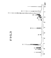
- Fig. 3 Shown in Fig. 3 is a H-NMRspectrum chart of 1"'-trifluoromethylheptyl ester of trans-4-[4'-(6"-n-decyloxy-2"-naphthoyloxy)phenyl]cyclohexane carboxylic acid having the following formula selected, for example, out of the carboxylic acid ester compounds having the above formula [I] prepared by the above-mentioned process.
- numerals 1 to 11 indicate the numbers of hydrogen atoms, and the numbers correspond to numbers attached to the peaks shown in Fig 3.
- Fig. 4 Shown in Fig. 4 is a 1 H-NMR spectrum chart of R-1"-trifluoromethylheptyl ester of 1,2,3,4-tetrahydro-6-(6'-n-heptyloxy-2'-naphthoyloxy)naphthalene-2-carboxylic acid having the following formula.
- numerals 1 to 10 indicate the numbers of hydrogen atoms, and the numbers correspond to numbers attached to the peaks shown in Fig 4.
- the carboxylic acid ester compounds having the formula [I] prepared by the above-mentioned process can be favorably employed as liquid crystal compounds.
- the phase transition temperatures of the liquid crystal compounds represented respectively by the formulae [115], [127] and [139] are set forth in Table 2.
- carboxylic acid ester compounds i.e., liquid crystal compounds
- the carboxylic acid ester compounds having the aforementioned formula [III] also include novel carboxylic acid ester compounds having the following formula [II] (i.e., aforementioned second carboxylic acid ester compound).
- the second carboxylic acid ester compound is represented by the following formula [II]:
- R 1 represents a group selected from the group consisting of an alkyl group having 3-20 carbon atoms, an alkoxy group having 3-20 carbon atoms and a halogenated alkyl group having 3-20 carbon atoms;
- C * represents an asymmetric carbon atom; and
- R 2 represents an alkyl group having 2-10 carbon atoms.
- R 1 when R 1 is an alkyl group having 3-20 carbon atoms, the alkyl group may be any of straight-chain, branched and alicyclic groups.
- the carboxylic esters in which R 1 is a straight-chain alkyl group exhibit excellent liquid crystal properties, because their molecules take a rigid structure extending in a straight line.
- the straight-chain alkyl groups preferred is a straight-chain alkyl group having 6-20 carbon atoms.
- straight-chain alkyl groups include a hexyl group, a heptyl group, an octyl group, a nonyl group, a decyl group, a undecyl group, a dodecyl group, a tetradecyl group, a hexadecyl group and an octadecyl group.
- R 1 is a halogenated alkyl group
- examples of such halogenated alkyl groups include groups obtained by substituting at least a part of hydrogen atoms of the above-mentioned alkyl groups with a halogen atom such as F, Cl, Br or I.
- alkoxy groups include alkoxy groups having the above-mentioned alkyl groups, for example, a hexoxy group, a heptoxy group, an octyloxy group, a nonyloxy group, a decyloxy group, a undecyloxy group, a dodecyloxy group, a tetradecyloxy group, a heptadecyloxy group, a hexadecyloxy group and an octadecyloxy group.
- R 2 represents an alkyl group having 2-10 carbon atoms, preferably an alkyl group having 2-6 carbon atoms.
- alkyl groups include an ethyl group, a propyl group, a butyl group, a pentyl group, a hexyl group, a heptyl group and an octyl group.
- particularly useful as liquid crystal compounds are compounds having a hexyl group (-C 6 H 13 ).
- R 2 is linked to an asymmetric carbon atom C * , and to the asymmetric carbon atom are linked a hydrogen atom and a methyl group (-CH 3 ). Further, to the residual linkage portion of the asymmetric carbon atom is linked a p-phenylene group (first phenylene group) through ester linkage.
- the p-phenylene group is linked to other p-phenylene group (second phenylene group) through ester linkage.
- this phenylene group is linked to 2,6-naphthalene group through ester linkage.
- the whole molecule preferably becomes linear, and therefore, particularly excellent as liquid crystal compounds are the compounds of the invention wherein two of p-phenylene groups are linked to 2,6-naphthalene group through ester linkage.
- carboxylic acid ester compounds having the above-mentioned formula [II] are concretely those having the following formulae [201] to [216].
- the carboxylic acid ester compounds represented by the above formula [II] can be also prepared by utilizing a combination of known synthesis techniques, as described in the preparation of the carboxylic acid ester compounds represented by the aforementioned formula [III].
- the carboxylic acid ester compounds having the formula [II] can be preferably employed as the liquid crystal compounds.
- phase transition temperatures of the liquid crystal compound represented by the formula [205] are set forth in Table 3.
- liquid crystal compounds When liquid crystal compounds are used singly as in the conventional cases, there are scarcely known liquid crystal compounds showing smectic phase within a wide temperature range as wide as 100 °C as in the case of the above-mentioned compound.
- liquid crystal elements there have been conventionally employed liquid crystal materials showing any one of a chiral smectic C phase, a chiral smectic F phase, a chiral smectic G phase, a chiral smectic H phase, a chiral smectic I phase, a chiral smectic J phase and a chiral smectic K phase.
- liquid crystal materials other than the liquid crystal materials showing a chiral smectic C phase are employed, the resulting liquid crystal elements are slow in response speed. Accordingly, driving with a chiral smectic C phase having a quick response speed has heretofore been considered to be advantageous in practical use.
- the liquid crystal elements can be employed not only in the chiral smectic C phase but also in the chiral smectic A phase by utilizing a method of driving liquid crystal elements in the smectic A phase as proposed previously by the present inventors (see: Japanese Patent Application No. 64(1989)-3632). Therefore, when the liquid crystal compounds containing the above-mentioned carboxylic acid ester compounds are employed, the obtained liquid crystal elements can be driven over a wide temperature range, and moreover, the liquid crystal elements filled with liquid crystal materials containing such liquid crystal compounds are excellent in high-speed response.
- liquid crystal materials as mentioned above can be used singly or in combination with other liquid crystal compounds.
- the liquid crystal compounds of the invention can be used as a principal ingredient in a smectic liquid crystal composition, or can be used as a minor ingredient in a liquid crystal composition containing other compound showing a smectic phase as a principal ingredient.
- the content of the above-mentioned carboxylic acid ester compound (i.e. liquid crystal compound) in the liquid crystal material constituting the liquid crystal element of the invention can be appropriately determined in consideration of the characteristics of the used liquid crystal compound, the viscosity of the composition, operating temperature of the resulting liquid crystal element, use application thereof, etc. In the invention, the content of the carboxylic acid ester compound (i.e.
- liquid crystal compound) in the liquid crystal material is generally in the range of 1-99 parts by weight, preferably in the range of 5-75 parts by weight. Further, in the liquid crystal material employable in the invention, the above-described carboxylic acid ester compounds may be contained alone or in combination of two or more compounds.
- liquid crystal compounds which can be used together with the carboxylic acid ester compounds having the above-mentioned formula [I], [II] or [III] in the liquid crystal material employable in the the invention, there can be mentioned, for example, (+)-4 ' -(2 " -methylbutyloxy)phenyl-6-octyloxynaphthalene-2-carboxylic ester, 4'- decyloxyphenyl-6-((+)-2 " -methylbutyloxy)naphthalene-2-carboxylic ester, and
- Shiff base type liquid crystal compounds such as azoxy type liquid crystal compounds such as benzoic acid ester type liquid crystal compounds such as cyclohexylcarboxylic acid ester type liquid crystal compounds such as phenyl type liquid crystal compounds such as terphenol type liquid crystal compounds such as cyclohexyl type liquid crystal compounds such as pyrimidine type liquid crystal compounds such as
- additives which can be incorporated into ordinary liquid crystal compositions, for example, conductivity imparting agents and lifetime improving agents, in addition to the above-mentioned carboxylic acid ester compounds and other liquid crystal compounds.
- liquid crystal materials employable in the invention can be prepared using the above-mentioned carboxylic acid ester compounds, and they can be also prepared by mixing the carboxylic acid ester compounds with other liquid crystal compounds and additives, if desired.
- the liquid crystal element of the invention filled with the above-mentioned liquid crystal material comprises basically a cell 33 which is composed of two transparent substrates 31 a and 31 facing each other and so arranged as to form a gap 34 therebetween and transparent electrodes 32a and 32b each provided on the inner side of each transparent substrate; a liquid crystal material 35 filled in the gap 34; and polarizing plates 36a and 36b each polarizing plate being arranged on each outer side of the cell 33.
- transparent substrates there can be employed for example glasses and transparent polymer plates.
- an undercoat layer i.e., a layerfor preventing permeation of unnecessary components
- silicon oxide or the like as its host component
- the transparent substrate when it is a glass substrate, generally has a thickness of from 0.01 to 1.0 mm.
- flexible transparent substrates can be also employed as the transparent substrates.
- at least one of the transparent substrates may be a flexible transparent substrate or both of them may be flexible transparent substrates.
- the flexible transparent substrates there can be employed, for example, polymer films.
- each transparent substrate On the surface of each transparent substrate is provided a transparent electrode.
- the transparent electrode can be formed by coating the surface of the transparent substrate with, for example, iridium oxide or tin oxide.
- the formation of the transparent electrode can be made utilizing conventionally known coating methods.
- the thickness of the transparent electrode is generally in the range of from 100 to 2,000 A.
- an orientation controlling layer i.e., orientation layer
- a ferroelectric layer On the transparent electrode which is provided on the transparent substrate as mentioned above may be provided an orientation controlling layer (i.e., orientation layer) or a ferroelectric layer.
- the orientation layer can be formed, for example, by chemical adsorption of an organic silane coupling agent or a polynuclear complex of carboxylic acid, or by rhombic deposition of silicon oxide or the like.
- the orientation layer can be also formed by applying a polyimide resin onto the transparent electrode, followed by rubbing the coated polyimide resin in a definite direction.
- the orientation layer may be so formed as to serve simultaneously as a spacer as will be mentioned later.
- Two sheets of the transparent substrate each having the transparent electrode thereon as illustrated above are arranged in such a manner that the two sheets of the transparent electrodes face each other and form therebetween a gap which is to be filled with a liquid crystal material.
- the width of the gap thus formed is usually in the range of 1 to 10 f..lm, preferably in the range of 1 to 5 f..lm.
- Such a gap as mentioned above can be easily formed, for example, by arranging two sheets of the substrates in such positions that a certain spacer is held therebetween.
- the spacer there can be employed, for example, a polyimide type polymer material obtained by patterning a photosensitive polyimide precursor.
- a mono- domain is formed by interfacial effect between the spacer and the liquid crystal material.
- an orientation film and the spacer can be integrated into one system.
- a method of adding a fiber to the liquid crystal material can be also employed other than the method of using the above-mentioned spacer. In this method, a certain gap can be held between the substrates owing to the fiber.
- liquid crystal material can be mixed with particles instead of the fiber, or may be mixed with the fiber together with the particles.
- the particles as referred to above include those made of melamine resin, urea resin or benzoguanamine resin having a particle diameter of from 1 to 10 ⁇ m.
- the two sheets of the transparent substrate so arranged as to form a gap therebetween in the manner described above are then generally sealed on their peripheries using a sealing material.
- a sealing material include epoxy resin and silicone resin, and they may be modified with acrylic material, silicone rubber, etc.
- the gap is filled with a liquid crystal material containing the aforementioned carboxylic acid ester compound represented by the formula [I], [II] or [III].
- the liquid crystal material filled in the gap of the liquid crystal cell can be oriented utilizing, for example, a temperature gradient method using a spacer edge or a monoaxial orientation controlling method such as surface treatment using an orientation film.
- the initial orientation of the liquid crystal material can be also conducted by applying an electric field using direct current bias voltage to the liquid crystal material under heating the liquid crystal material.
- the liquid crystal cell filled with the liquid crystal material and initially oriented as mentioned above is placed between two polarizing plates.
- These two polarizing plates are arranged in such a manner that an angle formed by polarization planes of the polarizing plates would be 70-110°.
- those two polarizing plates are so arranged that the polarization directions of the polarizing plates meet at right angle, that is, the above-mentioned angle becomes 90°.
- polarizing films prepared by stretching resin films such as polyvinyl alcohol resin film and polyvinyl butyral resin film in the presence of iodine or the like so as to impart polarization to the stretched films.
- the polarizing films as illustrated above may be laminated on the surface with other resin so as to have a multi-layer construction.
- the liquid crystal cell can be placed between the two polarizing plates as arranged in the above in such a manner that the cell forms an angle (rotation angle) within the range of from +10 0 to -10 0 (hereinafter abbreviated to ⁇ 10°) from the state wherein the amount of transmitted light is the smallest (i.e. the darkest state), preferably in the darkest state.
- the liquid crystal cell can be placed in a state to form an angle (rotation angle) within the range of ⁇ 10° from the state wherein the amount of transmitted light is the largest (i.e. the brightest state), preferably in the brightest state.
- Driving of the liquid crystal element of the present invention having such structure as mentioned above can be conducted by applying an electric field to the liquid crystal element.
- the liquid crystal element of the invention can be driven by applying thereto an electric field having been controlled to have a frequency of usually 1 Hz-100 KHz, preferably 10 Hz-10 KHz, and a voltage of usually 0.01-60 Vp-p/wm t , preferably 0.05-30 Vp-p/wm t (volatge per 1 f..lm in thickness).
- the liquid crystal element When the liquid crystal element is driven by application of an electric field, the amount of light that transmits this element comes to exhibit two kinds of hysteresis curves by changing a wave form (driving wave) of the electric field applied thereto. That is, the present inventor has been successful in exhibiting memorization in one liquid crystal element by employing two kinds of driving methods. Of the two driving methods, one is to utilize so-called double state stability, and the other is to utilize so-called triple state stability.
- a liquid crystal element using MHPOBC as a liquid crystal material is known as a liquid crystal element exhibiting the triple state stability, but it exhibits practically no double state stability.
- liquid crystal element of the present invention that either double state stability or triple state stability can be selected in one kind of liquid crystal element only by operation of changing the wave form (driving wave) of the electric field applied thereto.
- Fig. 6 is an oscillograph of a wave form showing a relationship between the amount of transmitted light and the applied voltage in a liquid crystal element exhibiting triple state stability
- Fig. 7 is an oscillograph of a wave form showing the same relationship in a liquid crystal element exhibiting double state stability.
- a liquid crystal cell filled with a liquid crystal material is placed between two polarizing plates whose polarization planes meet at right angles, so that the darkest state of the element is attained without applying an electric field thereto.
- Fig. 6 shows an example of an oscillographic wave form obtained at the time when a triangular wave of 10 Hz is applied to this liquid crystal element
- Fig. 7 shows an example of an oscillographic wave form obtained at the time when a triangular wave of 100 Hz is applied thereto.
- a favorable tri-stable state can be realized by application of an electric field of a relatively low frequency, for example, 0.001-50 Hz, preferably 0.1-30 Hz, to the element.
- the oscillographic wave form is gradually transformed into the bi-stable state as shown in Fig. 7 with increasing frequency of the electric field applied, and hence a favorable bi-stable state can be realized, for example, by applying an electric field having a frequency of 50 Hz-100 KHz, preferably 70 Hz-10 KHz to the liquid crystal element.
- a dark state can be attained when the applied voltage is 0 Vp-p, and in this case the contrast becomes markedly high.
- Figs. 8 and 9 each show an oscillographic wave form of a liquid crystal element in which a liquid crystal cell filled with a liquid crystal material is placed between two polarizing plates whose polarization planes meet at right angle, so that the brightest state of the element is attained.
- Fig. 8 shows an example of an oscillographic wave form obtained at the time when a triangular wave of 10 Hz is applied to the liquid crystal element
- Fig. 9 shows an example of an oscillographic wave form obtained at the time when a triangular wave of 100 Hz is applied to the liquid crystal element.
- this liquid crystal element there is a tendency similar to that in the above-mentioned liquid crystal elements, for example, a bi-stable state is attained by applying an electric field having a relatively high frequency.
- the electric field applied to the above-mentioned liquid crystal elements is preferably selected from among a rectangular wave (or pulse wave), triangular wave, sinusoidal wave (sine wave) and a combination thereof.
- a speed for driving the liquid crystal element can be increased by reducing the width of the applied electric field to not more than 10 msec, preferably in the range of from 0.01 to 10 msec, and in this region, the liquid crystal element of the invention may be used as a bi-stable state type liquid crystal element.
- the liquid crystal element of the invention can be used as a tri-stable state type liquid crystal element in the region where no so high driving is required.
- the width of an electric field used herein is intended to designate, for example in a rectangular wave, a length (i.e. time) of the electric field maintained at a given voltage.
- an electric field can be applied while varying a voltage between a negative voltage and a positive voltage through OV.
- a hysteresis curve showing a favorable double state stability can be formed, for example, by varying the applied voltage between -30 V and +30 V.
- an electric field can be applied in the manner similar to that of the above-mentioned case.
- this liquid crystal element may be applied an electric field having the above-mentioned wave form by varying a voltage between 0 and a positive voltage, or by varying a voltage between 0 and a negative voltage.
- a light modulation method utilizing, for example, light transmission properties shown by a hysteresis curve formed on a plus voltage side by application of an electric field wherein a voltage is varied in the range of 0 to +30 V.
- a light modulation method utilizing light transmission properties shown by a hysteresis curve formed at a minus voltage side by application of an electric field wherein a voltage is varied in the range of 0 to -30 V.
- the liquid crystal element of the invention is superior to liquid crystal elements of the prior art in that the element can be driven by utilizing two kinds of driving methods as mentioned above, and the memory effect of the element can be assured by suitably selecting a desired driving method out of the two methods according to the conditions under which the element is driven.
- the liquid crystal element as mentioned above can be used as ordinary liquid crystal elements, but it is particularly useful as a display element.
- Examples of the display elements include a large frame display, a multi-information display for automobiles, and a navigation display for automobiles. These display elements can be driven, according to the purposes for which they are used, by the above-mentioned driving methods as a bi-stable state type liquid crystal element or a tri-stable state type liquid crystal element.
- liquid crystal elements of the invention and the light modulation methods using the liquid crystal elements, stable states of two forms, namely a bistable state and a tri-stable state, can be attained by using only one kind of liquid crystal element.
- liquid crystal elements of the invention when used, a dark state having a sufficient darkness can be attained, and hence not only the contrast between the bright state and dark state can be prominently enhanced, but also a favorable memory effect can be assured.
- the carboxylic acid ester compounds having the aforementioned formulae [I], [II] and [III] employable in the liquid crystal elements are optically active.
- the carboxylic acid ester compounds represented formulae [I] and [II] have specific structure in which a ring structure such as a naphthalene ring structure is combined, and this specific structure is rigid. Hence, these compounds show smectic phase over a wide temperature range in the vicinity of room temperature, and can be favorably used as anti-ferroelectric liquid crystal compounds.
- the temperature for actuation of the liquid crystal phase of the liquid crystal compounds can be reduced or the temperature range therefor can be broadened without marring the anti-ferroelectric properties of the liquid crystal compounds.
- liquid crystal elements having a high speed response over a wide temperature range can be obtained by using the above-mentioned liquid crystal compounds or the liquid crystal compositions containing the liquid crystal compounds.
- liquid crystal compounds or the liquid crystal compositions containing the liquid crystal compounds can be favorably employed over a wide temperature range in the vicinity of room temperature as ferroelectric liquid crystal compounds or compositions.
- the time for scanning the display devices is markedly shortened.
- liquid crystal compounds of the invention have spontaneous polarization, and hence there can be obtained liquid crystal elements having favorable memory effect even after elimination of an electric field by using a thin film cell filled with the liquid crystal compounds.
- liquid crystal elements When such liquid crystal elements are used, power consumption can be reduced, a stable contrast can be obtained, and also a low voltage driving can be performed.
- the liquid crystal elements utilize smectic phase of the carboxylic acid ester compounds, so that they can be favorably employed for optical switching elements which are generally used over a wide temperature range.
- the obtained reaction mixture was added to 450 ml of water, and the resulting mixture was filtrated to obtain a viscous liquid.
- the viscous liquid was washed with hexane to obtain 2.54 g (6.4 mmol) of benzyl ester of trans-4-(4'-benzoyloxyphenyl)cyclohexane carboxylic acid.
- the reaction was carried out at room temperature for additional 10 hours.
- Hydrogen gas was passed through a mixture of 2.27 g (4.76 mmol) of R-1 "-trifluoromethylheptyl ester of trans-4-(4'-benzyloxyphenyl)cyclohexane carboxylic acid obtained in the third step, 1.6 g of a 5 % palladium- carbon catalyst and 57 ml of tetrahydrofuran with stirring at room temperature for 6.5 hours.
- the mixture was allowed to undergo reaction at room temperature for 8 hours.
- the reaction mixture was filtrated, and the obtained filtrate was concentrated.
- the concentrate was separated using column chromatography to obtain 0.58 g of a white solid.
- Fig. 3 shows a chart of 1 H-NMR spectrum of this compound.
- the obtained solid was washed with water, then dried and recrystallized using ethanol of 10 times (by weight) of the solid, so as to obtain 4.26 g (14.9 mmol) of 6-n-heptyloxy-2-naphthoic acid in the form of a white solid.
- the organic phase was concentrated under reduced pressure to obtain 3.54 g of a solid.
- the solid was recrystallized using hexane of 4 times (by weight) of the solid, to obtain 2.2 g (7.6 mmol) of 1,2,3,4-tetrahyd- ro-6-n-heptyloxy-2-naphthoic acid in the form of a white solid.
- a mixture of 2.40 g of the unpurified product obtained in the fourth step, 1.32 g of (20 mmol) of potassium hydroxide having purity of 85 %, 50 g of ethanol and 5 g of water was allowed to undergo reaction at reflux temperature for 13 hours. After cooling of the reaction mixture to room temperature, 200 ml of water was added to the reaction mixture and the mixture was acidified with 20 % hydrochloric acid. Then, a deposited light yellow solid was separated from the mixture through filtration. The solid was washed sequentially with water and hexane and then dried. Thus, 1.20 g (4.3 mmol) of 1,2,3,4-tetrahydro-6-benzyloxy-2-naphthoic acid was obtained.
- the reaction mixture was subjected to filtration, and the obtained filtrate was concentrated.
- the concentrate was separated using column chromatography, to obtain 0.34 g (0.76 mmol) of R-1'-trifluoromethylheptyl ester of 1,2,3,4-tetrahydro-6-benzyloxy-naphthalene-2-carboxylic acid in the form of a light yellow liquid.
- Hydrogen gas was passed through a mixture of 0.31 g (0.69 mmol) of R-1'-trifluoromethylheptyl ester of 1,2,3,4-tetrahydro-6-benzyloxy-naphthalene-2-carboxylic acid obtained in the sixth step, 0.3 g of a 5 % palladium-carbon and 30 ml of tetrahydrofuran with stirring at room temperature under ordinary pressure for 8 hours.
- the reaction mixture was filtrated using Celite which is a filtration assistant, and the obtained filtrate was concentrated to obtain 0.25 g (0.69 mmol) of R-1'-trifluoromethylheptyl ester of 1,2,3,4-tetrahydro-6-hydroxynaphthalene-2-carboxylic acid in the form of a light yellow liquid.
- the reaction mixture was filtrated, and the obtained filtrate was concentrated.
- the concentrate was separated using column chromatography to obtain 0.32 g of a colorless semi-solid.
- Fig. 4 shows a chart of 1 H-NMR spectrum of this compound.
- the obtained reaction mixture was added to 500 ml of water, and the resulting mixture was subjected to filtration to obtain benzyl ester of 4'-benzyloxybiphenyl-4-carboxylic acid in the form of a white solid.
- reaction mixture was added to 400 ml of water, and then to the mixture was added hydrochloric acid to acidify the system, so as to obtain a white solid. Then, the white solid was filtrated to obtain 7.95 g (26.2 mmol) of 4'-benzyloxybiphenyl-4-carboxylic acid in the form of a white solid.
- the reaction was carried out at room temperature for additional 4 hours.
- Hydrogen gas was passed through a mixture of 1.15 g (2.44 mmol) of R-1 "-trifluoromethylheptyl ester of 4'-benzyloxybiphenyl-4-carboxylic acid obtained in the third step, 0.9 g of a 5 % palladium-carbon catalyst and 50 ml of tetrahydrofuran with stirring at room temperature for 6 hours.
- the mixture was allowed to undergo reaction at room temperature for 8 hours.
- the reaction mixture was filtrated, and the obtained filtrate was concentrated.
- the concentrate was separated using column chromatography to obtain 0.03 g of a white solid.
- the reaction was carried out at room temperature for additional 10 hours.
- the reaction mixture was filtrated, and the obtained filtrate was concentrated.
- the concentrate was separated using column chromatography to obtain 2.30 g (4.28 mmol) of benzyl ester of 4-(6'-n-decyloxy-2'-na- phthoyloxy)benzoic acid in the form of a white solid.
- Hydrogen gas was passed through a mixture of 2.15 g (4 mmol) of benzyl ester of 4-(6'-n-decyloxy-2'-na- phthoyloxy)benzoic acid obtained in the first step, 1 g of a 5 % palladium-carbon catalyst and 30 ml of tetrahydrofuran with stirring at room temperature for 8 hours.
- the mixture was allowed to undergo reaction at room temperature for another 8 hours.
- the reaction mixture was filtrated, and the obtained filtrate was concentrated.
- the concentrate was separated using column chromatography to obtain 0.52 g of a colorless semi-solid.
- Hydrogen gas was passed through a mixture of 1.58 g (4 mmol) of R-1'-trifluoromethylheptyl ester of 4-benzyloxybenzoic acid obtained in the first step, 0.5 g of a 5 % palladium-carbon and 30 ml of ethyl acetate with stirring at room temperature under normal pressure for 9 hours.
- the reaction mixture was filtrated using Celite which is a filtration assistant, and the obtained filtrate was concentrated.
- Hydrogen gas was passed through a mixture of 2.33 g (4.7 mmol) of benzyl ester of 4-(6'-heptyloxy-2'-na- phthoyloxy)benzoic acid obtained in the third step, 1.0 g of a 5 % palladium-carbon and 30 ml of tetrahydrofuran with stirring at room temperature under normal pressure for 8 hours.
- the reaction mixture was filtrated using Celite which is a filtration assistant, and the obtained filtrate was concentrated.
- the concentrate was then recrystallized using toluene to obtain 1.42 g (3.5 mmol) of 4-(6'-n-hep- tyloxy-2-naphthoyloxy)benzoic acid in the form of a white solid.
- the mixture was allowed to undergo reaction at room temperature for 8 hours.
- the reaction mixture was filtrated, and the obtained filtrate was concentrated.
- the concentrate was separated using column chromatography to obtain 0.63 g of a colorless semi-solid.
- the carboxylic acid ester compound represented by the formula [304] prepared as above and the compound represented by the following formula (Cr-1) were mixed with each other in a ratio therebetween of 51 : 49, by weight, to prepare a liquid crystal material (i.e., liquid crystal composition).
- phase transition temperatures of this liquid crystal composition are set forth in Table 5, and in the table the phase transition temperatures of the compound having the above formula (Cr-1) are also set forth.
- the carboxylic acid ester compound represented by the above formula [302] was melted and introduced into a gap (kept under reduced pressure) of a cell, the cell being composed of two substrates with ITO transparent electrodes, each substrate being provided with an orientation controlling film (thickness: 150 A) made of polyimide (PIQ-5400, a product of Hitachi Kasei Kogyo K.K.) on the inner surface thereof as shown in Fig. 5.
- the two polyimide films were so rubbed as to have orientation directions thereof nearly parallel to each other and in the same direction.
- the cell thus filled with the liquid crystal material was heated to 200 °C, kept at 200 °C for 5 minutes, and then cooled at a rate of 1 °C/min to 60 °C, to prepare a liquid crystal element.
- the above-mentioned cell was prepared in the following manner.
- Polyimide was applied to a glass substrate having ITO transparent electrode film thereon.
- Coating of the polyimide (PIQ-5400, a product of Hitachi Kasei Kogyo K.K.) on the ITO transparent electrode was conducted by a spin coating method.
- the polyimide was diluted with N-methylpyrrolidone to prepare a 1.2 A solution, and the solution was then spin-coated at 2000 r.p.m.
- the polyimide solution thus coated was cured by heating at 325 °C for 30 minutes, whereupon a polyimide film of 150 to 200 A in thickness was formed.
- the polyimide film was then rubbed with a nylon cloth in one direction, thereby imparting an ability of orientating the liquid crystal thereto.
- an epoxy adhesive was applied to each of the polyimide film-coated glass substrates by means of silk screen printing in order to bond two substrates to each other and to control a gap of the cell.
- the epoxy adhesive was prepared by mixing an adhesive base (LCB-304B, a product of EHC) with a curing agent (LCB-304B, a product of EHC) and beads (GP-20, a product of EHC) for controlling cell gap in the proportion of 130 : 30 : 3.
- One of the glass substrates was coated with the epoxy adhesive and laminated to other glass substrate in such a manner that the polyimide films faced each other.
- the epoxy adhesive thus coated was cured under such curing conditions that heating was conducted at 50 °C for 15 minutes, at 60 °C for 15 minutes, at 70 °C for 15 minutes, at 80 °C for 15 minutes, at 125 °C for 30 minutes and at 170 °C for 60 minutes, to combine the substrates with each other.
- a liquid crystal element was prepared by placing the above-mentioned liquid crystal cell filled with the liquid crystal material between two polarizing plates whose polarization planes meet at right angles so that the darkest state was attained in the element.
- a triangular wave of 30 V pop was applied to the liquid crystal element to measure an intensity of transmitted light, and as a result, an oscillographic wave shown in Fig. 6 was obtained by application of a frequency of 10 Hz and, an oscillographic wave shown in Fig. 7 was obtained by application of a frequency of 100 Hz.
- this liquid crystal element attained the contrast of 34 between the time when 0 V was applied and the time when +30 V (or -30 V) was applied by application of a triangular wave of 10 Hz.
- this liquid crystal element attained the contrast of 15 between the time when -12 V was applied and the time when +12 V was applied by application a triangular wave of 100 Hz.
- the dark state can be attained by applying a voltage of 0 V using a low frequency, in particular, whereby the contrast between the dark state and the bright state can be prominently enhanced.
- the contrast mentioned above was determined by measuring the intensity of the transmitted light in the bright state and in the dark state while changing a voltage applied to the liquid crystal element, and calculating therefrom the ratio of I (bright state) / I (dark state).
- a liquid crystal element was prepared by placing the above-mentioned liquid crystal cell filled with the liquid crystal material between two polarizing plates whose polarization planes meet at right angles in such a manner that the brightest state was attained in the element.
- a triangular wave of 30 V pop was applied to the liquid crystal element to measure an intensity of transmitted light, and as a result, an oscillographic wave shown in Fig. 8 was obtained by application of a frequency of 10 Hz, and an oscillographic wave shown in Fig. 9 was obtained by application of a frequency of 100 Hz.
- the liquid crystal element of the invention in which the liquid crystal cell is placed between two polarizing plates whose polarization planes meet at right angles in such a manner that the brightest state is attained in the element was able to secure a favorable memory effect using a high frequency, in particular.
Landscapes
- Chemical & Material Sciences (AREA)
- Organic Chemistry (AREA)
- Crystallography & Structural Chemistry (AREA)
- Engineering & Computer Science (AREA)
- Materials Engineering (AREA)
- Liquid Crystal Substances (AREA)
- Organic Low-Molecular-Weight Compounds And Preparation Thereof (AREA)
Applications Claiming Priority (6)
| Application Number | Priority Date | Filing Date | Title |
|---|---|---|---|
| JP166392/90 | 1990-06-25 | ||
| JP2166392A JPH0455811A (ja) | 1990-06-25 | 1990-06-25 | 液晶素子および該素子を用いた光変調方法 |
| JP331873/90 | 1990-11-29 | ||
| JP331874/90 | 1990-11-29 | ||
| JP2331873A JP2752246B2 (ja) | 1990-11-29 | 1990-11-29 | カルボン酸エステル化合物、液晶化合物および液晶組成物 |
| JP2331874A JP2812552B2 (ja) | 1990-11-29 | 1990-11-29 | カルボン酸エステル化合物、液晶化合物および液晶組成物 |
Publications (3)
| Publication Number | Publication Date |
|---|---|
| EP0465048A2 true EP0465048A2 (de) | 1992-01-08 |
| EP0465048A3 EP0465048A3 (en) | 1992-07-08 |
| EP0465048B1 EP0465048B1 (de) | 1996-09-11 |
Family
ID=27322683
Family Applications (1)
| Application Number | Title | Priority Date | Filing Date |
|---|---|---|---|
| EP91305546A Expired - Lifetime EP0465048B1 (de) | 1990-06-25 | 1991-06-19 | Carbonsäureesterverbindung, flüssigkristalline Verbindung, flüssigkristalline Zusammensetzung, flüssigkristallines Element und Methode zur Lichtmodulation |
Country Status (8)
| Country | Link |
|---|---|
| EP (1) | EP0465048B1 (de) |
| KR (1) | KR940001850B1 (de) |
| CN (1) | CN1060462A (de) |
| AT (1) | ATE142613T1 (de) |
| CA (1) | CA2045325A1 (de) |
| DE (1) | DE69121989D1 (de) |
| MY (1) | MY107894A (de) |
| TW (1) | TW207529B (de) |
Cited By (5)
| Publication number | Priority date | Publication date | Assignee | Title |
|---|---|---|---|---|
| EP0586263A1 (de) * | 1992-08-19 | 1994-03-09 | Showa Shell Sekiyu Kabushiki Kaisha | Flüssigkristallverbindung |
| EP0587280A1 (de) * | 1992-07-14 | 1994-03-16 | Mitsui Petrochemical Industries, Ltd. | Antiferroelektrisches, flüssigkristallines Verbundmaterial, Verfahren zur dessen Herstellung sowie Flüssigkristallelement zur dessen Anwendung |
| EP0566380A3 (de) * | 1992-04-14 | 1994-04-27 | Mitsui Petrochemical Ind | |
| EP0566379A3 (de) * | 1992-04-14 | 1994-04-27 | Mitsui Petrochemical Ind | |
| EP0617109A1 (de) * | 1993-03-25 | 1994-09-28 | Mitsui Petrochemical Industries, Ltd. | Flüssigkristallmaterial, Flüssigkristallzusammensetzung und Flüssigkristallelement |
Families Citing this family (1)
| Publication number | Priority date | Publication date | Assignee | Title |
|---|---|---|---|---|
| US5725798A (en) * | 1991-12-27 | 1998-03-10 | Mitsui Petrochemical Industries, Ltd. | Carboxylate compounds, liquid crystal materials liquid crystal compositions and liquid crystal elements |
Family Cites Families (10)
| Publication number | Priority date | Publication date | Assignee | Title |
|---|---|---|---|---|
| JPH0645573B2 (ja) * | 1985-07-04 | 1994-06-15 | 三井東圧化学株式会社 | 液晶化合物および液晶組成物 |
| GB8610349D0 (en) * | 1986-04-28 | 1986-06-04 | Bdh Ltd | 6-hydroxy-2-naphthoic acid derivatives |
| US4943651A (en) * | 1988-03-07 | 1990-07-24 | Mitsui Petrochemical Industries, Ltd. | Novel substitued naphthalene compounds and liquid crystal compositions containing same |
| CA1329252C (en) * | 1988-03-10 | 1994-05-03 | Hardee, Gregory E. | Light modulation element |
| DE68916105T2 (de) * | 1988-04-28 | 1994-11-17 | Showa Shell Sekiyu | Flüssigkristall-Verbindungen mit Naphthalennucleus. |
| DE68917013T2 (de) * | 1988-05-12 | 1994-12-01 | Mitsui Petrochemical Ind | Naphthalen-Verbindung und dieselbe enthaltende flüssigkristalline Zusammensetzung. |
| CA2013901A1 (en) * | 1989-04-06 | 1990-10-06 | Mitsui Petrochemical Industries, Ltd. | Carboxylic acid ester compounds, and their related matters and method of producing the same |
| MY106839A (en) * | 1989-08-18 | 1995-08-30 | Mitsui Petrochemical Ind | Carboxylate compounds, liquid crystal compositions containing said compounds and liquid crystal elements. |
| JPH03106850A (ja) * | 1989-09-20 | 1991-05-07 | Mitsubishi Kasei Corp | エステル誘導体 |
| EP0422996B1 (de) * | 1989-10-06 | 1995-04-12 | Showa Shell Sekiyu Kabushiki Kaisha | Flüssigkristall-Verbindung |
-
1991
- 1991-06-15 TW TW080104668A patent/TW207529B/zh active
- 1991-06-19 EP EP91305546A patent/EP0465048B1/de not_active Expired - Lifetime
- 1991-06-19 MY MYPI91001102A patent/MY107894A/en unknown
- 1991-06-19 AT AT91305546T patent/ATE142613T1/de not_active IP Right Cessation
- 1991-06-19 DE DE69121989T patent/DE69121989D1/de not_active Expired - Lifetime
- 1991-06-24 CA CA002045325A patent/CA2045325A1/en not_active Abandoned
- 1991-06-25 CN CN91104428A patent/CN1060462A/zh active Pending
- 1991-06-25 KR KR1019910010562A patent/KR940001850B1/ko not_active Expired - Fee Related
Cited By (8)
| Publication number | Priority date | Publication date | Assignee | Title |
|---|---|---|---|---|
| EP0566380A3 (de) * | 1992-04-14 | 1994-04-27 | Mitsui Petrochemical Ind | |
| EP0566379A3 (de) * | 1992-04-14 | 1994-04-27 | Mitsui Petrochemical Ind | |
| EP0587280A1 (de) * | 1992-07-14 | 1994-03-16 | Mitsui Petrochemical Industries, Ltd. | Antiferroelektrisches, flüssigkristallines Verbundmaterial, Verfahren zur dessen Herstellung sowie Flüssigkristallelement zur dessen Anwendung |
| US5389287A (en) * | 1992-07-14 | 1995-02-14 | Mitsui Petrochemical Industries, Ltd. | Antiferroelectric liquid crystal composite material, process for preparing the same, and liquid crystal element using the same |
| EP0586263A1 (de) * | 1992-08-19 | 1994-03-09 | Showa Shell Sekiyu Kabushiki Kaisha | Flüssigkristallverbindung |
| US5330678A (en) * | 1992-08-19 | 1994-07-19 | Showa Shell Sekiyu Kabushiki Kaisha | Liquid crystal compound |
| EP0617109A1 (de) * | 1993-03-25 | 1994-09-28 | Mitsui Petrochemical Industries, Ltd. | Flüssigkristallmaterial, Flüssigkristallzusammensetzung und Flüssigkristallelement |
| US5422039A (en) * | 1993-03-25 | 1995-06-06 | Mitsui Petrochemical Industries, Ltd. | Liquid crystal material, liquid crystal composition and liquid crystal element |
Also Published As
| Publication number | Publication date |
|---|---|
| KR920000695A (ko) | 1992-01-29 |
| MY107894A (en) | 1996-06-29 |
| CN1060462A (zh) | 1992-04-22 |
| KR940001850B1 (ko) | 1994-03-09 |
| ATE142613T1 (de) | 1996-09-15 |
| DE69121989D1 (de) | 1996-10-17 |
| TW207529B (de) | 1993-06-11 |
| EP0465048A3 (en) | 1992-07-08 |
| EP0465048B1 (de) | 1996-09-11 |
| CA2045325A1 (en) | 1991-12-26 |
Similar Documents
| Publication | Publication Date | Title |
|---|---|---|
| KR940003580B1 (ko) | 액정 라세미 혼합물, 액정 조성물 및 액정소자와, 액정소자 제조방법 및 그의 용도 | |
| EP0566380B1 (de) | Carboxylic-Säureester-Verbindung, flüssigkristallines Material, flüssigkristalline Zusammensetzungen und flüssigkristallines Element | |
| EP0566379A2 (de) | Tetralin-Verbindung, flüssigkristallines Material, flüssigkristalline Zusammensetzung und flüssigkristallines Element | |
| EP0431929B1 (de) | Carboxylsäure-Verbindungen, flüssigkristalline Zusammensetzungen und sie enthaltende Flüssigkristallelemente und Verfahren zu optischer Modulation unter Verwendung dieser Elemente | |
| EP0465048A2 (de) | Carbonsäureesterverbindung, flüssigkristalline Verbindung, flüssigkristalline Zusammensetzung, flüssigkristallines Element und Methode zur Lichtmodulation | |
| EP0435240B1 (de) | Flüssigkristalline Verbindung | |
| US5356561A (en) | Carboxylate compounds, liquid crystal compositions and liquid crystal elements containing said compounds and method of optical modulation using said elements | |
| EP0413585B1 (de) | Carboxylatverbindungen, diese Verbindungen enthaltende flüssigkristalline Zusammensetzungen und flüssigkristalliner Bauteil | |
| EP0617109B1 (de) | Flüssigkristallmaterial, Flüssigkristallzusammensetzung und Flüssigkristallelement | |
| EP0549347B1 (de) | Karbonsäureesterverbindungen, flüssigkristalline Stoffe, flüssigkristalline Zusammensetzungen und flüssigkristalline Bauteile | |
| JP2732765B2 (ja) | 強誘電性液晶表示素子 | |
| JPH06329591A (ja) | 液晶材料、液晶組成物および液晶素子、ならびにエステル化合物 | |
| JP2752246B2 (ja) | カルボン酸エステル化合物、液晶化合物および液晶組成物 | |
| JP3357390B2 (ja) | カルボン酸エステル化合物、液晶材料、液晶組成物及び液晶素子 | |
| JP3357407B2 (ja) | カルボン酸エステル化合物、液晶材料、液晶組成物及び液晶素子 | |
| JP3357389B2 (ja) | カルボン酸エステル化合物、液晶材料、液晶組成物及び液晶素子 | |
| JP2992335B2 (ja) | カルボン酸エステル化合物、液晶化合物および液晶組成物 | |
| JPH0625098A (ja) | カルボン酸エステル化合物、液晶材料、液晶組成物及び液晶素子 | |
| JPH069500A (ja) | テトラリン化合物、液晶材料、液晶組成物および液晶素子 | |
| JPH07316555A (ja) | 液晶材料、液晶組成物および液晶素子 | |
| JPH0476092A (ja) | 液晶素子およびその製造方法ならびに液晶素子の用途 | |
| JPH0812622A (ja) | テトラリン化合物およびその製造方法、ならびにテトラリン系カルボン酸エステル化合物、液晶材料、液晶組成物および液晶素子 | |
| JPH04235950A (ja) | 三重結合を有する光学活性化合物 | |
| JPH0491189A (ja) | 液晶組成物およびその用途 | |
| JPH0699353B2 (ja) | 光学活性ヒドロキシビフェニル |
Legal Events
| Date | Code | Title | Description |
|---|---|---|---|
| PUAI | Public reference made under article 153(3) epc to a published international application that has entered the european phase |
Free format text: ORIGINAL CODE: 0009012 |
|
| AK | Designated contracting states |
Kind code of ref document: A2 Designated state(s): AT BE CH DE DK ES FR GB GR IT LI LU NL SE |
|
| PUAL | Search report despatched |
Free format text: ORIGINAL CODE: 0009013 |
|
| AK | Designated contracting states |
Kind code of ref document: A3 Designated state(s): AT BE CH DE DK ES FR GB GR IT LI LU NL SE |
|
| 17P | Request for examination filed |
Effective date: 19920916 |
|
| 17Q | First examination report despatched |
Effective date: 19940221 |
|
| GRAH | Despatch of communication of intention to grant a patent |
Free format text: ORIGINAL CODE: EPIDOS IGRA |
|
| GRAH | Despatch of communication of intention to grant a patent |
Free format text: ORIGINAL CODE: EPIDOS IGRA |
|
| GRAA | (expected) grant |
Free format text: ORIGINAL CODE: 0009210 |
|
| AK | Designated contracting states |
Kind code of ref document: B1 Designated state(s): AT BE CH DE DK ES FR GB GR IT LI LU NL SE |
|
| PG25 | Lapsed in a contracting state [announced via postgrant information from national office to epo] |
Ref country code: AT Effective date: 19960911 Ref country code: DK Effective date: 19960911 Ref country code: BE Effective date: 19960911 Ref country code: LI Effective date: 19960911 Ref country code: NL Free format text: LAPSE BECAUSE OF FAILURE TO SUBMIT A TRANSLATION OF THE DESCRIPTION OR TO PAY THE FEE WITHIN THE PRESCRIBED TIME-LIMIT Effective date: 19960911 Ref country code: FR Effective date: 19960911 Ref country code: ES Free format text: THE PATENT HAS BEEN ANNULLED BY A DECISION OF A NATIONAL AUTHORITY Effective date: 19960911 Ref country code: GR Free format text: LAPSE BECAUSE OF FAILURE TO SUBMIT A TRANSLATION OF THE DESCRIPTION OR TO PAY THE FEE WITHIN THE PRESCRIBED TIME-LIMIT Effective date: 19960911 Ref country code: CH Effective date: 19960911 Ref country code: IT Free format text: LAPSE BECAUSE OF FAILURE TO SUBMIT A TRANSLATION OF THE DESCRIPTION OR TO PAY THE FEE WITHIN THE PRE;WARNING: LAPSES OF ITALIAN PATENTS WITH EFFECTIVE DATE BEFORE 2007 MAY HAVE OCCURRED AT ANY TIME BEFORE 2007. THE CORRECT EFFECTIVE DATE MAY BE DIFFERENT FROM THE ONE RECORDED.SCRIBED TIME-LIMIT Effective date: 19960911 |
|
| REF | Corresponds to: |
Ref document number: 142613 Country of ref document: AT Date of ref document: 19960915 Kind code of ref document: T |
|
| REF | Corresponds to: |
Ref document number: 69121989 Country of ref document: DE Date of ref document: 19961017 |
|
| PG25 | Lapsed in a contracting state [announced via postgrant information from national office to epo] |
Ref country code: SE Effective date: 19961211 |
|
| PG25 | Lapsed in a contracting state [announced via postgrant information from national office to epo] |
Ref country code: DE Effective date: 19961212 |
|
| NLV1 | Nl: lapsed or annulled due to failure to fulfill the requirements of art. 29p and 29m of the patents act | ||
| REG | Reference to a national code |
Ref country code: CH Ref legal event code: PL |
|
| PG25 | Lapsed in a contracting state [announced via postgrant information from national office to epo] |
Ref country code: GB Free format text: LAPSE BECAUSE OF NON-PAYMENT OF DUE FEES Effective date: 19970619 |
|
| PG25 | Lapsed in a contracting state [announced via postgrant information from national office to epo] |
Ref country code: LU Free format text: LAPSE BECAUSE OF NON-PAYMENT OF DUE FEES Effective date: 19970630 |
|
| PLBE | No opposition filed within time limit |
Free format text: ORIGINAL CODE: 0009261 |
|
| STAA | Information on the status of an ep patent application or granted ep patent |
Free format text: STATUS: NO OPPOSITION FILED WITHIN TIME LIMIT |
|
| 26N | No opposition filed | ||
| GBPC | Gb: european patent ceased through non-payment of renewal fee |
Effective date: 19970619 |