EP0465149A2 - Datenaufbereitungsverfahren und -gerät - Google Patents
Datenaufbereitungsverfahren und -gerät Download PDFInfo
- Publication number
- EP0465149A2 EP0465149A2 EP91305866A EP91305866A EP0465149A2 EP 0465149 A2 EP0465149 A2 EP 0465149A2 EP 91305866 A EP91305866 A EP 91305866A EP 91305866 A EP91305866 A EP 91305866A EP 0465149 A2 EP0465149 A2 EP 0465149A2
- Authority
- EP
- European Patent Office
- Prior art keywords
- automatic
- data
- user
- display
- processes
- Prior art date
- Legal status (The legal status is an assumption and is not a legal conclusion. Google has not performed a legal analysis and makes no representation as to the accuracy of the status listed.)
- Granted
Links
Images








Classifications
-
- G—PHYSICS
- G06—COMPUTING OR CALCULATING; COUNTING
- G06F—ELECTRIC DIGITAL DATA PROCESSING
- G06F3/00—Input arrangements for transferring data to be processed into a form capable of being handled by the computer; Output arrangements for transferring data from processing unit to output unit, e.g. interface arrangements
- G06F3/01—Input arrangements or combined input and output arrangements for interaction between user and computer
- G06F3/048—Interaction techniques based on graphical user interfaces [GUI]
- G06F3/0481—Interaction techniques based on graphical user interfaces [GUI] based on specific properties of the displayed interaction object or a metaphor-based environment, e.g. interaction with desktop elements like windows or icons, or assisted by a cursor's changing behaviour or appearance
- G06F3/04817—Interaction techniques based on graphical user interfaces [GUI] based on specific properties of the displayed interaction object or a metaphor-based environment, e.g. interaction with desktop elements like windows or icons, or assisted by a cursor's changing behaviour or appearance using icons
-
- G—PHYSICS
- G06—COMPUTING OR CALCULATING; COUNTING
- G06F—ELECTRIC DIGITAL DATA PROCESSING
- G06F9/00—Arrangements for program control, e.g. control units
- G06F9/06—Arrangements for program control, e.g. control units using stored programs, i.e. using an internal store of processing equipment to receive or retain programs
- G06F9/44—Arrangements for executing specific programs
- G06F9/451—Execution arrangements for user interfaces
Definitions
- the present invention relates to a method and an apparatus for editing data. It is applicable to data in any form, but is particularly, although not exclusively, concerned with the case where the data is used to generate a graphics image, which is to be edited by a user.
- the term 'editing' should be given a wide meaning, on comprising any modification to the data, on the relationships between the data.
- an editing system establishes a plurality of user-triggerable editing operations (editing commands), and the user then edits the data by selecting one of those editing commands to carry out a particular editing operation. When that editing operation has been completed, the user can then select the same or a different editing command for editing more of the data.
- editing commands user-triggerable editing operations
- the user can then select the same or a different editing command for editing more of the data.
- editing in this way will take a considerable amount of time.
- the macro command enables the user to save time, since the separate editing commands do not have to be individually selected and their operation is carried out together.
- a macro command has to be converted, by a suitable processing means, into the individual editing commands, but, by establishing such a macro command, the user need not worry about the separate editing commands needed to carry out a particular editing operation determined by the macro command.
- Such a system is known in conventional Computer Aided Design (CAD) systems, an example of such a system is disclosed on pages 18 and 19 of "Concept Station Catalog” (by Dentsu International Information Service, Ltd. Nov A RDE 903Cl 3000, Nov., 1989).
- CAD Computer Aided Design
- a manual entitled “Drawing System HICID/DRAFT/W User Interface” from Hitachi, Ltd., (2050G Manual 205G-7-602, July 1988) discussed an arrangement in which new commands can be added as desired by the user.
- the macro commands comprise only those operations which have been combined by the user.
- Automatic editing system is disclosed in e.g. "A Knowledge-Based Cooperative Information Processing Method" from the Information Processing Society Thesis Journal Vol. 30, No. 4, pages 427 to 438, April 1989). In this disclosure, a train schedule was created as an automatic process, using a tree-structure of routine operations.
- the present invention addresses these problems, and tries to overcome them. In practice, it is not normally possible for these problems wholly to be overcome, since some depend on the nature of the editing operation itself. For example, no matter how reliable the system, it cannot wholly prevent an inexperienced user from omitting an important operation. However, the present invention seeks at least to ameliorate at least some of these problems.
- the present invention proposes that a plurality of automatic operations be defined for investigating relationships between the data to be edited. Then, the user can select one or more of those automatic operations, edit a particular part of the data, and investigate the relationships of that part of the data which has been edited using the automatic operation. Then, a visual indication of the status of the selected automatic process is given on the same display as that carrying an image of the data which is being edited.
- the visual indication given by the first aspect of the present invention may simply indicate that the selected automatic process is operating. However, it is desirable that the user is presented with more information than this, and a second aspect of the present invention proposes that the visual indication is in the form of an icon which then changes as the automatic operation progresses.
- This aspect of the present invention is applicable to an arrangement in which there is only one automatic process, so there is no selection as in the first aspect of the present invention, and thus the second aspect is independent of the first. However, the two may be used in combination.
- an icon as a form of visual indication.
- the word "icon” is used in a wide sense represent an image component in the form of a graphic element and/or a word or words, and the present invention is not limited to any particular form of icon.
- an automatic process may be provided which merely monitors the relationship between the data, or part of the data, and generates a suitable visual indication of its status (e.g. by a changing icon), and then generates a message to the user.
- an automatic process which itself performs an editing operation on the data, so as e.g. to ensure that the data conforms to a predetermined rule irrespective of the editing by the user.
- an automatic process could be defined which ensures that furniture items do not block doors or other routes. The automatic operation could then move furniture items automatically to prevent this occurring, when the user changes the position of doors in the lay-out.
- these two possibilities could be combined, in that the automatic operation could be arranged to edit the data automatically, if that were possible within predetermined limits, and to generate a message to the user when such automatic editing within those limits was not possible.
- the actual indication (icon) is located relative to the image on the display at a point which gives a linking between the part of the data which the automatic operation investigates and the image of that part of the data. This presents the user with a more immediate visual relationship between the automatic operation and that part of the data on which it acts. This is particularly important where the automatic operation is to edit data which the user proposes to edit, in which case the visual indication (icon) should be located proximate the cursor which indicates the part of the image corresponding to the data which the user is editing. Alternatively, when two automatic processes edit the same data (dependent on different relationships), then the visual indications (icons) of those too automatic processes should be located adjacent each other.
- the processes which investigate the relationships between the data are automatic, it may be possible for the user to inhibit the start of a particular process. This may be useful, for example, where the user intends to carry out a series of related editing operations, and wants the automatic process to operate only when the series of automatic operations has been completed.
- the inhibited automatic process may then be triggered by a suitable start instruction from the user.
- the automatic processes may all be defined in advance, or it is possible for the user to create one or more further automatic processes by combining existing processes in a manner similar to the "macro" instructions discussed earlier.
- a further visual indication (icon) may then be associated with the newly-created automatic process.
- the present invention as described in Figs. 1 to 6, forms an interactive data editing system which has a plurality of automatic processes and in which the user edits or processes data interactively.
- the system has automatic process libraries, and automatic processes loaded in the libraries may be selected, released, or generated during data editing. Individual routine operations may then be performed by the automatic processes, and data can be interactively edited by the user (operator) only when a higher level editing decision is required. Hence, non-routine operations can be performed efficiently.
- the word "editing” in the present specification includes not only “editing” in the narrow sense of deleting data, but as also “processing", "generation” and/or “evaluation” of the data. Thus, editing includes general data processing in a wide sense.
- Fig. 1 shows a display of an interactive Computer Aided Design (CAD) system embodying the present invention.
- CAD Computer Aided Design
- an interactive screen has a display including an editing frame 100 on which the target data (for example, data representing the shape of the loading of an automobile is displayed as an image 101).
- the display also has a library frame 102 displaying visual indications representing automatic processes for automatically performing individual operations (for example, wheel base calculation, which is an example of a routine partial task in the design of an automobile body), and an automatic process generation frame 103 for generating new automatic processes.
- the automatic processes are illustrated on the screen by icons 104, which are located the editing frame 100, the library frame 102, or the generation frame 103 depending on the process. As will be discussed in more detail below, the position of each of the icons 104 indicates whether of the corresponding automatic process is activated, or not. Thus, the automatic processes corresponding to the icons 104 within the editing frame 100 are currently active A plurality of libraries may be created, each containing a plurality of automatic processes, and then the corresponding icons are selectively displayed in the library frame 102.
- Fig. 1 (b) shows a method for determining an automatic process to be operated by moving (hereinafter 'dragging') an icon 104 identifying an automatic process from the library frame 102 to the editing frame 100.
- a cursor 105 is used to specify the icon 104 which is to be dragged from the library frame 102 to the editing frame 100 (thereby selecting the corresponding automatic process for activation.
- an icon may be dragged or from the editing frame 100 to the library frame 102 (thereby canceling the activation of the corresponding automatic process).
- Fig. 1 (c) shows an example of the generation of an automatic process.
- Automatic process definition data is established within the generation frame 103, which data will define the automatic process to be carried out, and the automatic process is activated by moving the process icon 104 from the generation frame 103.
- This embodiment has the advantage that any activated automatic process is clearly indicated by a corresponding icon and the user can recognize it easily. By replacing “selection”, “release”, or “generation” of an automatic process with a graphic operation, the operation efficiency improved.
- the icon 104 preferably changes in shape in dependence on the progress of the automatic process (for example, the process may have a sleeping status, monitoring status, permission wait status, or action status as will be discussed later). Therefore, the shape or configuration of the icon helps to inform the user of the decision(s) needed.
- Fig. 2 shows the mutual interaction of the target data, user, and an automatic process of the present invention using the interactive CAD system discussed above as an embodiment of the appearance of the display.
- the mutual interactions may be as follows:
- the user may understand visually the operation of the automatic process(es) and changes in the target data, and a user friendly system can be constructed.
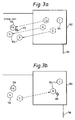
- Fig. 3 shows an embodiment in which automatic processes are grouped.
- the display shows a group icon 106 corresponding to the group containing automatic processes A and B.
- the automatic processes A and B are simultaneously selected by dragging the group icon 106 from the library frame 102 to the editing frame 100.
- the icons 104 corresponding to processes A and B are dragged to the editing frame 100 together.
- the groups icon 106 is moved back to the library frame, the processes of the group are simultaneously disactivated.
- automatic processes which have already been selected, need not be selected again.
- Fig. 3 (b) shows a method for releasing one of a group of automatic processes which have been selected by the operation described with reference to Fig. 3 (a).
- the icon 104 corresponding to process B is dragged back to the library frame 102.
- This embodiment has the advantage either a group automatic processes of the group members can be activated or disactivated together, or a single process of that group can be operated.
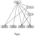
- Fig. 4 shows an example of the configuration of an automatic process library. This example shows the relationship between the library, groups, and automatic processes as a multiple tree structure. In a simple tree structure, the relationship between these items is fixed, while in a multiple tree structure, a flexible combination of automatic processes is available according to interaction with the user, and data can be edited or processed efficiently and correctly.
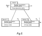
- Fig. 5 shows a method for linking the target data to a corresponding automatic process.
- the target data is assumed to have an object-oriented hierarchical structure.
- the data of an object 110 has a pointer 111 to the corresponding automatic process group.
- the automatic process group member indicated by the pointer 111 is automatically selected.
- the automatic process group when an object of the target data is specified, the automatic process group can also be selected automatically. Therefore, the arrangement for the advantage that the automatic process control is not wasteful and the number of user operations may be minimized.
- Fig. 6 shows a method for corresponding the editing procedure data to the automatic process.
- the operation procedure data is indicated as a flow chart in Fig. 6 (b) having partial task elements 120 shown in Fig. 6 (a) as components thereof.
- the partial task elements 120 comprise a partial task name 121, a pointer 122 to the corresponding automatic process group, partial task descriptive data 123, and a pointer group 124 to the next partial task to be performed.
- the partial task descriptive data 123 comprises the contents of the information to be displayed on the display, information specific to the target data, and partial task end conditions.
- the automatic process libraries used are all visible. However, this is not essential. If the user is an expert and understands the automatic processes loaded, he can select, release, or generate automatic processes by direct input (using a mouse or keys). It is not always necessary to have generation frame 103 for the automatic generation of processes but such a frame 103 may be formed in dependence on the data editing or processing to be carried out.
- Fig. 7 shows the configuration of an example of an interactive data editing apparatus according to another embodiment of the present invention.
- the interactive data editing apparatus shown in Fig. 7 comprises a data input display unit 11 and target data 13, and a plurality of automatic processes 22.
- the automatic processes 22 operate independently in parallel and always monitor (as indicated by arrow 18) the status of the target data 13.
- each automatic process 22 carries out a corresponding editing operation 14.
- Icons 19 is displayed on the display in corresponding with each automatic process 22 and the icon 19 changes in position and shape according to the status of each corresponding automatic process 22. Since the automatic processes 22 may perform actions automatically, even if the user enters no specific command, the user does not need to memorize all the commands. By noting the position and shape of the icon 19, the user can check visually the status of each automatic process 22.
- the icon 19 may be personified and the expression, clothing, belongings, position, and posture thereof may change according to the status of the automatic process, the user can consider the automatic process as being equivalent to a person. As a result, the operation and status of the automatic process can be understood more easily (the idea of a personified icon is disclosed in Japanese Patent Application Laid-Open No. 61-18035).
- the icon position is determined on the basis of the location of the data which is to be edited by the corresponding automatic process.
- the icon for example, can always be located near the location of the corresponding data and the user can immediately recognize the data to be acted on by each automatic process.
- Each automatic process operates using parametric data parameters as a target for monitoring or action. Since the partial parameters of the parametric data are corrected, the entire shape is continuously corrected, the amount of data to be monitored by the automatic process can be restricted.
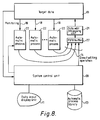
- Fig. 8 shows an example in which automatic processes are operated in parallel in a multitask processing computer, treating each automatic process as a task.
- the editing system comprises a system control unit 20 for processing user commands or generating or erasing automatic processes, target data 13 located in a common memory, a plurality of automatic processes 22, a data edit processing unit 21, and a FIFO buffer 27.
- the monitoring operation 18 of each automatic process 22 is performed by referring directly to the common memory.
- Actions are performed in a batch by sending an instruction for a direct editing operation 14 to the data edit processing unit 21.
- An automatic process library 23 is used as a file for accumulating a plurality of execution programs.
- the automatic process library stores a plurality of automatic processes, and the user can selectively operate one of them by "selecting” or “releasing” it. Therefore, the automatic processes can be created or controlled separately from the rest of the system so as to prevent it to be miniaturized as much as possible.
- Fig. 9 shows a transition diagram illustrating the operation states of an automatic process 22. This example defines six operation states, being a sleeping state 30, a monitoring state 31, a permission wait state 32, an action state 33, a warning or suggestion state 34 and a waiting state 35.
- the sleeping state 30 corresponds to the case where the automatic process is inactive, at its corresponding icon is in the automatic process library.
- the monitoring status 31 corresponds to the case where the automatic process is monitoring data.
- the permission wait state 32 corresponds to the case where the automatic process is waiting for permission for action, because the monitoring target is in a predetermined state.
- the action state 33 corresponds to the case where the automatic process is executing an action.
- the warning or suggestion state 34 corresponds to the case where, after executing an action, a message is generated for the user.
- the waiting state 35 corresponds to the case where the corresponding automatic process has been selected, but has then been rendered inactive without returning the corresponding icon to the library frame. Such a state may be desirable when the user wishes temporarily to inactivate a particular automatic process.
- a first transition is performed by the following procedure.
- the appropriate automatic process is selected from the automatic processes loaded in the automatic process library by the user or another automatic process.
- the sleeping state changes to the monitoring state 31 by a "select" instruction from the user or another automatic process, and the automatic process starts monitoring the appropriate data.
- That "select" instruction may correspond to the dragging of the icon corresponding to the automatic process from the library frame to the editing frame.
- the automatic process may be put into the monitoring state immediately after the movement of the corresponding icon as it is dragged from the library frame, has ceased. In such circumstances, there are then three possible transitions out of that monitoring state.
- the user may be desirable temporarily to inhibit the monitoring of data by that automatic process.
- the user may cause the process to change to the waiting state 35, in which state it will remain until the user returns it to the monitoring state.
- the user may inactivate the automatic process by release instruction, in which case the automatic process returns to the sleeping state.
- the release instruction may correspond to the dragging of the corresponding icon from the editing frame to the library frame. This returns the automatic process to the automatic process library.
- the user may supply a release instruction, returning the automatic process from the permission wait state 32 to the sleeping state 30.
- the automatic process When the automatic process is in the action state 33, it carries out an appropriate action on the data. There are then two possibilities. Firstly, the action may be completed, and the process then returns to the monitoring state 31, as shown by the "execution end" arrow in Fig. 9. Alternatively, however, it may be desirable for the automatic process to generate a message to the user, in which case the process changes to the warning or suggestion state 34 from the action state 33.
- the action of the automatic process may be to detect the breaking of that relationship, and to signal to the user a warning that the relationship has been broken, by changing to the warning or suggestion state 34. It can readily be appreciated that any information or message could be supplied to the user in this state 34, such as suggestions for further editing of the data.
- the automatic process may return to the monitoring state 31.
- the factors which determine whether an automatic process changes directly from the monitoring state 31 to the action state 33, or first changes to the permission waits state 32 may be determined by a suitable identifier in the set-up of the automatic process. By changing that identifier, the user may then determine whether the transition from the monitoring state 31 is direct or not. This has particular value when the user creates an new automatic process. In that case, at least for the first few times the automatic process is activated, the user may want to monitor closely the action of that automatic process, in which case it is desirable that the user knows when the automatic process will take effect. Thus, an initial transition to the permission wait state 32 permits the user to control when the automatic process carries out its action. If the user finds that the operation on the automatic process is satisfactory and reliable, detailed checking of its operation may no longer be necessary, in which case the user may then arrange for the automatic process to change directly from the monitoring state 31 to the action state 33.
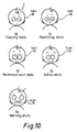
- Fig. 10 shows different configurations of the icon 19 corresponding to the various states of Fig. 9. As illustrated, the icon is personified, so that the user may more readily relate to the status of the operation being carried out by the automatic process. In Fig. 10, the personified icon is assumed to have the character of a workaholic.
- the character represented by the icon 19 has its eyes closed.
- the character represented by the icon 19 has a disappointed look, because it is not working.
- the permission wait state 32 the character represented by the icon 19 has an impatient look, waiting for an instruction to work.
- the action state 33 the character represented by the icon 19 has a happy look, because it is working.
- the warning state 34 the character represented by the icon 19 is shouting something to the user. No separate icon configuration is needed for the waiting state 35, and the same configuration as the sleeping state 30 can be used.
- Fig. 11 shows an example of definition means for automatic processes.
- Fig. 11 (a) shows the specification for the automatic process definition language.
- the monitoring specification description section and the action specification description section in the definition language use a syntax which is the same as that of an existing computer high level language (for example, the C language).
- Fig. 11 (b) shows the procedure for creating the form of execution for the automatic processes. This procedure is executed in the system control unit 20 of Fig. 8. It is possible that variables are used as target data for monitoring or action and specified on the screen for execution.
- the automatic process definition mechanism in this embodiment can define automatic processes when the user specifies the particular location of the target data on the screen as a monitoring or action target.
- the mechanism has the advantage that, even if the user does not recognize the detailed structure of an automatic process, he can define it easily.
- the partial task control mechanism 24 comprises target data to be edited by each partial task, automatic processes which operate, a target data memory 26 for storing each state of the display during operation, an automatic process library 23, and a displayed data memory 25.
- An editing target and an automatic process for each partial operation may be duplicated, though the state of the display is intrinsic to the partial task.
- an identifier for the partial task is assigned to each item of the displayed data memory 25, and the target data memory 26 and a pointer to the automatic process library 23 are provided in the displayed data memory 25.
- the corresponding partial task control mechanism 24 searches for the partial operation in the displayed data memory 25 and retrieves the target data and the automatic process for the partial task.
- the data saved for a partial task will subsequently be called "partial task data".
- the partial task control mechanism stores the content of each partial task as partial task data. Therefore, when the user halts the operation once and then restarts it, he can perform the operation intermittently in a continuous environment.
- the partial task control mechanism copies the partial task data and creates new operation data. When new partial task data is generated by copying a similar partial task, the necessary automatic process group already exists in the new partial task data. Therefore, the possibility that the user misses some check items necessary in the procedure is small.
- the target data is shape model data
- the data input display unit 11 comprises a graphic display unit and a tablet mouse.
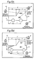
- Fig. 13 shows an example of the design of an interactive CAD system which uses the present invention.
- a partial task for determining the major dimensions of the design of an automobile body is considered. It is assumed that standard partial task data is already available.
- Fig. 13 (a) shows the display generated by of the data input display unit 11 immediately after one of the standard partial task data has been. On the display, an image 12 indicates the target data and icons 19 corresponding to the automatic processes are displayed. In the example of Fig. 13 (a), two types of automatic processes operate.
- FIG. 13 (e) considers a base of a process which determines the wheel height h, by a wheel height process 64.
- the height h will be the same for the front and back wheels. Therefore, if the user changes the wheel height h, the same automatic process must operate for the front and back wheel.
- the icon representing the wheel height process 64 is duplicated, as shown by arrow 65 in Fig. 13 (f) so that there are then two icons representing the wheel height process 64, both of which moves to the active state, shown in Fig. 13 (f) when the wheel height h is changed.
- routine operations can be started only by specifying partial tasks (in this discussion the "routine operations" do not correspond to the routine operations used in known systems and the user operation sequence, for example, is not specified).
- This example has the advantage in that the extent of operation automation can be easily changed by adding only non-standard automatic processes.
- the example also has the advantage that, on the basis of partial task data created by a veteran designer, as inexperienced designer may design a product of the same type.
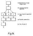
- FIG. 14 is a flow chart showing the examination procedure for the plurality of designs. The operation is first performed using single target data (a). For examination of a plurality of designs, the current operation status is loaded as partial task data (b), and then it is copied (c). At this time, each partial task data is the same. Each of the data may become an editing target for different automatic processes thereafter or may be changed to different designs by different operations performed by the user (d) or (e).
- the design examination operation is loaded as a partial task. Therefore, the embodiment has the advantage that, when another design is generated, the partial task data can be re-used.
- a plurality of automatic processes are generally controlled by an identifier.
- the corresponding automatic processes start. Since each automatic process executes an action in reaction to changes in the target data, flexible automation is available, as compared with a macro command whose operation procedure is fixed.
- the target data is copied for a target and each target data can be operated as an operation target for different automatic processes.
- a plurality of plans may be created in parallel and the efficiency of editing is improved.
- routine operations are performed by automatic processes and the user can edit data only when a more complex decision is required. Therefore, the efficiency of operation, including non-routine operations may be improved.
- the present invention has the advantage that the operation efficiency is improved and a user friendly system may be constructed.
Landscapes
- Engineering & Computer Science (AREA)
- Theoretical Computer Science (AREA)
- Software Systems (AREA)
- General Engineering & Computer Science (AREA)
- Human Computer Interaction (AREA)
- Physics & Mathematics (AREA)
- General Physics & Mathematics (AREA)
- User Interface Of Digital Computer (AREA)
- Stored Programmes (AREA)
- Digital Computer Display Output (AREA)
Applications Claiming Priority (2)
| Application Number | Priority Date | Filing Date | Title |
|---|---|---|---|
| JP17741890A JP3279556B2 (ja) | 1990-07-06 | 1990-07-06 | データ編集方法 |
| JP177418/90 | 1990-07-06 |
Publications (3)
| Publication Number | Publication Date |
|---|---|
| EP0465149A2 true EP0465149A2 (de) | 1992-01-08 |
| EP0465149A3 EP0465149A3 (en) | 1993-01-27 |
| EP0465149B1 EP0465149B1 (de) | 1998-06-03 |
Family
ID=16030582
Family Applications (1)
| Application Number | Title | Priority Date | Filing Date |
|---|---|---|---|
| EP91305866A Expired - Lifetime EP0465149B1 (de) | 1990-07-06 | 1991-06-28 | Datenaufbereitungsverfahren und -gerät |
Country Status (4)
| Country | Link |
|---|---|
| US (1) | US5712654A (de) |
| EP (1) | EP0465149B1 (de) |
| JP (1) | JP3279556B2 (de) |
| KR (1) | KR100203522B1 (de) |
Cited By (4)
| Publication number | Priority date | Publication date | Assignee | Title |
|---|---|---|---|---|
| WO1997005540A1 (fr) * | 1995-07-26 | 1997-02-13 | Benjamin Badinter | Procede de visualisation d'informations sur un ecran d'ordinateur, support anime d'informations associe, et systeme pour sa mise en oeuvre |
| GB2311151A (en) * | 1996-02-29 | 1997-09-17 | Jba Holdings Plc | Object browser and manipulation system |
| EP1653336A3 (de) * | 2004-11-01 | 2007-01-03 | Nec Corporation | Tragbares Endgerät und Verfahren zur Bearbeitung der Anzeigedaten dafür |
| EP1958056A4 (de) * | 2005-11-23 | 2009-11-18 | Bluebeam Software Inc | Verfahren zum verfolgen von datenobjekten unter verwendung verwandter thumbnails in einem paletten-fenster |
Families Citing this family (16)
| Publication number | Priority date | Publication date | Assignee | Title |
|---|---|---|---|---|
| US5828575A (en) * | 1996-05-06 | 1998-10-27 | Amadasoft America, Inc. | Apparatus and method for managing and distributing design and manufacturing information throughout a sheet metal production facility |
| JP3671590B2 (ja) * | 1997-01-23 | 2005-07-13 | ソニー株式会社 | 表示方法、表示装置及び通信装置 |
| US6360357B1 (en) * | 1999-06-10 | 2002-03-19 | Dassault Systems | Adding code in an application during runtime to enrich object behavior |
| US7240297B1 (en) | 2000-06-12 | 2007-07-03 | International Business Machines Corporation | User assistance system |
| JP4442042B2 (ja) * | 2001-02-23 | 2010-03-31 | パナソニック電工株式会社 | 画像処理プログラム作成方法およびそのシステム |
| US20040030710A1 (en) * | 2001-05-21 | 2004-02-12 | Thomas Shadle | Rules-based task browser for engineering systems |
| JP2005505409A (ja) * | 2001-10-09 | 2005-02-24 | ミリポア・コーポレイション | 化学プロセス機械プログラミングシステム |
| FR2850180B1 (fr) * | 2003-01-17 | 2005-04-29 | Denis Gueyffier | Solution de messagerie electronique utilisant des icones dans le shell du systeme d'exploitation |
| US7398129B2 (en) * | 2004-10-07 | 2008-07-08 | Amada Company, Limited | Representation of sheet metal part models |
| EP2410681A3 (de) * | 2005-03-31 | 2012-05-02 | Yamaha Corporation | Steuergerät für ein Musiksystem bestehend aus mehreren Geräten die über ein Netz mit einander verbunden sind, und integriertes Computerprogramm für die Steuerung vom Musiksystem |
| US10162477B2 (en) * | 2008-07-23 | 2018-12-25 | The Quantum Group, Inc. | System and method for personalized fast navigation |
| US20100149573A1 (en) * | 2008-12-17 | 2010-06-17 | Xerox Corporation | System and method of providing image forming machine power up status information |
| CN101951490B (zh) * | 2009-12-31 | 2012-09-05 | 四川虹欧显示器件有限公司 | 提高显示图像质量的方法、装置和等离子显示器 |
| JP5436406B2 (ja) * | 2010-12-27 | 2014-03-05 | シャープ株式会社 | 画像形成装置、プログラムおよび記録媒体 |
| US20160328423A1 (en) * | 2015-05-05 | 2016-11-10 | Cisco Technology, Inc. | System and method for data change detection and recency indication |
| CN108132749B (zh) * | 2017-12-21 | 2020-02-11 | 维沃移动通信有限公司 | 一种图像编辑方法及移动终端 |
Family Cites Families (12)
| Publication number | Priority date | Publication date | Assignee | Title |
|---|---|---|---|---|
| US4315315A (en) * | 1971-03-09 | 1982-02-09 | The Johns Hopkins University | Graphical automatic programming |
| JPS58163009A (ja) * | 1982-03-23 | 1983-09-27 | Toyoda Mach Works Ltd | 対話式デ−タ入力機能を備えた数値制御装置における加工情報入力方法 |
| US4813013A (en) * | 1984-03-01 | 1989-03-14 | The Cadware Group, Ltd. | Schematic diagram generating system using library of general purpose interactively selectable graphic primitives to create special applications icons |
| JPS6118035A (ja) * | 1984-07-03 | 1986-01-25 | Canon Inc | 電子機器 |
| NL8600831A (nl) * | 1986-04-02 | 1987-11-02 | Oce Nederland Bv | Werkwijze voor het opwekken en bewerken van modellen van twee- of driedimensionale objecten in een computer en voor het weergeven van die modellen op een display. |
| US4827404A (en) * | 1986-04-14 | 1989-05-02 | Schlumberger Technology Corporation | Method and system for computer programming |
| US5040131A (en) * | 1987-12-23 | 1991-08-13 | International Business Machines Corporation | Graphical processing |
| US4951039A (en) * | 1988-04-18 | 1990-08-21 | Motorola, Inc. | Animated data display interleaving |
| US5021976A (en) * | 1988-11-14 | 1991-06-04 | Microelectronics And Computer Technology Corporation | Method and system for generating dynamic, interactive visual representations of information structures within a computer |
| US5212635A (en) * | 1989-10-23 | 1993-05-18 | International Business Machines Corporation | Method and apparatus for measurement of manufacturing technician efficiency |
| US5121319A (en) * | 1989-10-23 | 1992-06-09 | International Business Machines Corporation | Method and apparatus for selective suspension and resumption of computer based manufacturing processes |
| US5134560A (en) * | 1989-10-23 | 1992-07-28 | International Business Machines Corporation | Method and system for generation of manufacturing process plans |
-
1990
- 1990-07-06 JP JP17741890A patent/JP3279556B2/ja not_active Expired - Fee Related
-
1991
- 1991-06-28 EP EP91305866A patent/EP0465149B1/de not_active Expired - Lifetime
- 1991-07-02 KR KR1019910011163A patent/KR100203522B1/ko not_active Expired - Fee Related
-
1995
- 1995-04-21 US US08/426,276 patent/US5712654A/en not_active Expired - Fee Related
Cited By (8)
| Publication number | Priority date | Publication date | Assignee | Title |
|---|---|---|---|---|
| WO1997005540A1 (fr) * | 1995-07-26 | 1997-02-13 | Benjamin Badinter | Procede de visualisation d'informations sur un ecran d'ordinateur, support anime d'informations associe, et systeme pour sa mise en oeuvre |
| GB2311151A (en) * | 1996-02-29 | 1997-09-17 | Jba Holdings Plc | Object browser and manipulation system |
| US5852439A (en) * | 1996-02-29 | 1998-12-22 | Jba Holdings Plc | Object browser and manipulation system |
| GB2311151B (en) * | 1996-02-29 | 2000-11-15 | Jba Holdings Plc | An object browser and manipulation system |
| EP1653336A3 (de) * | 2004-11-01 | 2007-01-03 | Nec Corporation | Tragbares Endgerät und Verfahren zur Bearbeitung der Anzeigedaten dafür |
| US8060838B2 (en) | 2004-11-01 | 2011-11-15 | Nec Corporation | Portable terminal and display data editing method for the same |
| US8914745B2 (en) | 2004-11-01 | 2014-12-16 | Lenovo Innovations Limited (Hong Kong) | Portable terminal and display data editing method for the same |
| EP1958056A4 (de) * | 2005-11-23 | 2009-11-18 | Bluebeam Software Inc | Verfahren zum verfolgen von datenobjekten unter verwendung verwandter thumbnails in einem paletten-fenster |
Also Published As
| Publication number | Publication date |
|---|---|
| US5712654A (en) | 1998-01-27 |
| KR100203522B1 (ko) | 1999-06-15 |
| JP3279556B2 (ja) | 2002-04-30 |
| EP0465149A3 (en) | 1993-01-27 |
| JPH0465772A (ja) | 1992-03-02 |
| EP0465149B1 (de) | 1998-06-03 |
Similar Documents
| Publication | Publication Date | Title |
|---|---|---|
| EP0465149B1 (de) | Datenaufbereitungsverfahren und -gerät | |
| US6366300B1 (en) | Visual programming method and its system | |
| US5960199A (en) | Model trace view for object-oriented systems | |
| US5157763A (en) | Visually assisted method for transfer of data within an application or from a source application to a receiving application | |
| US4829468A (en) | Print control system | |
| US6239800B1 (en) | Method and apparatus for leading a user through a software installation procedure via interaction with displayed graphs | |
| US5838563A (en) | System for configuring a process control environment | |
| JP3258379B2 (ja) | メニュー表示装置 | |
| JPH05289840A (ja) | ウィンドウ表示装置および方法 | |
| EP3321788A1 (de) | Vorrichtung zur editierung von objekten | |
| JP2502179B2 (ja) | デ―タベ―ス・システム及び該システムの操作方法 | |
| CN104823159A (zh) | 用于改变人机界面设备中对象的方法和设备 | |
| EP0613145A2 (de) | Graphische Benutzerschnittstelle für Dateikarten mit visueller Darstellung von Videodaten | |
| JP2000056888A (ja) | ユーザーインターフェイス設定方法及びその装置 | |
| KR20000018932A (ko) | 게임 개발 시스템 및 그 방법 | |
| JPH11296571A (ja) | 干渉チェック装置およびそのプログラム記録媒体 | |
| JPH04257973A (ja) | 設計支援装置及び設計支援方法 | |
| JPH11134085A (ja) | ビル自動システム内のリアルタイム情報をモニタし、制御する方法およびその装置 | |
| JP2001283238A (ja) | 対話型データ編集装置及び方法 | |
| JPH0778215A (ja) | 業務プログラムの実行方法 | |
| JPH02208693A (ja) | マルチウィンドウ画面表示装置 | |
| JP4455400B2 (ja) | 作画エディタ装置、制御用表示装置、並びに、そのプログラムおよび記録媒体 | |
| JP2619487B2 (ja) | フアイル操作方式 | |
| JP2000132295A (ja) | Gui動作仕様記述装置及びgui制御装置及びguiシステム | |
| JPH0784829A (ja) | インタラクティブ型マルチウインドウプログラム自動テ スト装置 |
Legal Events
| Date | Code | Title | Description |
|---|---|---|---|
| PUAI | Public reference made under article 153(3) epc to a published international application that has entered the european phase |
Free format text: ORIGINAL CODE: 0009012 |
|
| 17P | Request for examination filed |
Effective date: 19910817 |
|
| AK | Designated contracting states |
Kind code of ref document: A2 Designated state(s): DE FR GB |
|
| PUAL | Search report despatched |
Free format text: ORIGINAL CODE: 0009013 |
|
| AK | Designated contracting states |
Kind code of ref document: A3 Designated state(s): DE FR GB |
|
| 17Q | First examination report despatched |
Effective date: 19960924 |
|
| GRAG | Despatch of communication of intention to grant |
Free format text: ORIGINAL CODE: EPIDOS AGRA |
|
| GRAG | Despatch of communication of intention to grant |
Free format text: ORIGINAL CODE: EPIDOS AGRA |
|
| GRAH | Despatch of communication of intention to grant a patent |
Free format text: ORIGINAL CODE: EPIDOS IGRA |
|
| GRAH | Despatch of communication of intention to grant a patent |
Free format text: ORIGINAL CODE: EPIDOS IGRA |
|
| RBV | Designated contracting states (corrected) |
Designated state(s): FR GB |
|
| GRAA | (expected) grant |
Free format text: ORIGINAL CODE: 0009210 |
|
| REG | Reference to a national code |
Ref country code: DE Ref legal event code: 8566 |
|
| AK | Designated contracting states |
Kind code of ref document: B1 Designated state(s): FR GB |
|
| ET | Fr: translation filed | ||
| PLBE | No opposition filed within time limit |
Free format text: ORIGINAL CODE: 0009261 |
|
| STAA | Information on the status of an ep patent application or granted ep patent |
Free format text: STATUS: NO OPPOSITION FILED WITHIN TIME LIMIT |
|
| 26N | No opposition filed | ||
| REG | Reference to a national code |
Ref country code: GB Ref legal event code: IF02 |
|
| PGFP | Annual fee paid to national office [announced via postgrant information from national office to epo] |
Ref country code: FR Payment date: 20020524 Year of fee payment: 12 |
|
| PGFP | Annual fee paid to national office [announced via postgrant information from national office to epo] |
Ref country code: GB Payment date: 20020527 Year of fee payment: 12 |
|
| PG25 | Lapsed in a contracting state [announced via postgrant information from national office to epo] |
Ref country code: GB Free format text: LAPSE BECAUSE OF NON-PAYMENT OF DUE FEES Effective date: 20030628 |
|
| GBPC | Gb: european patent ceased through non-payment of renewal fee |
Effective date: 20030628 |
|
| PG25 | Lapsed in a contracting state [announced via postgrant information from national office to epo] |
Ref country code: FR Free format text: LAPSE BECAUSE OF NON-PAYMENT OF DUE FEES Effective date: 20040227 |
|
| REG | Reference to a national code |
Ref country code: FR Ref legal event code: ST |