EP0465157A1 - Fluidbett-Verkokungsapparat und Kontrollverfahren dafür - Google Patents
Fluidbett-Verkokungsapparat und Kontrollverfahren dafür Download PDFInfo
- Publication number
- EP0465157A1 EP0465157A1 EP91305878A EP91305878A EP0465157A1 EP 0465157 A1 EP0465157 A1 EP 0465157A1 EP 91305878 A EP91305878 A EP 91305878A EP 91305878 A EP91305878 A EP 91305878A EP 0465157 A1 EP0465157 A1 EP 0465157A1
- Authority
- EP
- European Patent Office
- Prior art keywords
- feed
- atomization
- injector
- nozzle
- feed injector
- Prior art date
- Legal status (The legal status is an assumption and is not a legal conclusion. Google has not performed a legal analysis and makes no representation as to the accuracy of the status listed.)
- Granted
Links
Images






Classifications
-
- B—PERFORMING OPERATIONS; TRANSPORTING
- B01—PHYSICAL OR CHEMICAL PROCESSES OR APPARATUS IN GENERAL
- B01J—CHEMICAL OR PHYSICAL PROCESSES, e.g. CATALYSIS OR COLLOID CHEMISTRY; THEIR RELEVANT APPARATUS
- B01J8/00—Chemical or physical processes in general, conducted in the presence of fluids and solid particles; Apparatus for such processes
- B01J8/18—Chemical or physical processes in general, conducted in the presence of fluids and solid particles; Apparatus for such processes with fluidised particles
- B01J8/1809—Controlling processes
-
- C—CHEMISTRY; METALLURGY
- C10—PETROLEUM, GAS OR COKE INDUSTRIES; TECHNICAL GASES CONTAINING CARBON MONOXIDE; FUELS; LUBRICANTS; PEAT
- C10G—CRACKING HYDROCARBON OILS; PRODUCTION OF LIQUID HYDROCARBON MIXTURES, e.g. BY DESTRUCTIVE HYDROGENATION, OLIGOMERISATION, POLYMERISATION; RECOVERY OF HYDROCARBON OILS FROM OIL-SHALE, OIL-SAND, OR GASES; REFINING MIXTURES MAINLY CONSISTING OF HYDROCARBONS; REFORMING OF NAPHTHA; MINERAL WAXES
- C10G11/00—Catalytic cracking, in the absence of hydrogen, of hydrocarbon oils
- C10G11/14—Catalytic cracking, in the absence of hydrogen, of hydrocarbon oils with preheated moving solid catalysts
- C10G11/18—Catalytic cracking, in the absence of hydrogen, of hydrocarbon oils with preheated moving solid catalysts according to the "fluidised-bed" technique
- C10G11/187—Controlling or regulating
Definitions
- the invention is directed to an apparatus and process for controlling feed injector atomization in a fluid hydrocarbon conversion and cracking unit.
- the introduction of feed into a conversion and cracking zone is effected by a plurality of feed injectors which are employed to optimize the atomization of the feed by providing a preselected ⁇ P or pressure drop across a throat section of each of said feed injectors.
- the invention is directed to a process for controlling a reactor by optimizing the atomization of the feed introduced into a hydrocarbon conversion and cracking zone.
- a plurality of feed injectors each comprising a variable throat section thereof, are employed to optimize the feed atomization.
- atomization with respect to the effluent from a feed injector, is meant to encompass the following atomization characteristics: the average or mean feed droplet size, droplet size distribution, and spray pattern.
- Spray pattern refers to spray angles and shape, for example, cone, fan, etc.
- a degree of feed atomization characterized by a smaller average droplet size, narrow droplet size distribution, and well dispersed spray pattern will result in less coke and less dry gas, thereby tending to maximize liquid yields.
- atomization of the feed into relatively fine droplets may be selected to match the size and distribution of the solid particles employed in the reaction zone.
- a larger relative average droplet size and wide distribution, including a portion of droplets significantly larger in size than average, and a spray pattern not well dispersed can result in a significant increase in coke formation.
- the selected degree of atomization will depend on the process objectives. For example, in order to maximize LPG and naphtha, a fine droplet size may not be ideal. It is believed that droplet size and distribution are dominant factors in achieving yield objectives. Data suggests that two different spray patterns may have drastically different effects on yields.
- An oil-only feed may be "pressure atomized" and/or sprayed into the reactor.
- a lower molecular weight media is injected into the oil feed. Suitable media include hydrogen, steam, nitrogen, low molecular wt. reactor off-gas, and C6 ⁇ hydrocarbons.
- a steam/oil mixture is used as the feed stream to the reactor. In a preferred embodiment, this steam/oil mixture is passed through a variable throat feed injector nozzle.
- the ratio of steam/oil can be adjusted during operations based on changes in oil feed type and properties. The amount of steam in the mixture influences the density of the mixture and will therefore have an impact on atomization.
- General commercial practice, suitable with the present process is,to use about 0.50 wt% steam for light feed types and about 3.0 to 5.0 wt% steam for heavy, more viscous feed types.
- a good indicator or measure of the state of atomization of the feed handled is the pressure drop ⁇ P across the nozzle of the feed injector.
- a parameter related to nozzle pressure drop can be used as a measure of atomization.
- pressure drop is directly related to nozzle cross-sectional area in the preferred feed injectors of the present invention.
- the nozzle resistance coefficient defined below in the examples, is a good measure of atomization. Data relating nozzle droplet size, droplet size distribution and spray pattern to nozzle resistance coefficient or ⁇ P can be obtained experimentally, as detailed below in the examples.
- Correlations can also serve as a basis for making estimates of the performance of a particular variable throat feed injector design.
- Nozzle geometry can effect spray pattern, liquid droplet size and droplet size distribution, and is therefore reflected in the nozzle resistance coefficient.
- the desired degree of atomization may depend on the process or operating objectives.
- atomization of the feed into a conversion and cracking zone can be selected to compensate for changing product yield and/or quality objectives in a multivariable constraint control or LP control or non-linear LP control environment.
- An example of this would be naphtha product liquid yield and research octane quality.
- the reactor yields can be adjusted to optimize the economic benefit from the fluidized hydrocarbon conversion and cracking process on a refinery's operation. This is extremely important at refineries where on-stream blending is conducted.
- the degree of atomization may be used as a control variable, changing in real time. For example, both yields and temperatures can be varied by varying the degree of atomization.
- the use of variable throat feed injectors to control yield and selectivity in a fluid catalytic cracking unit (FCCU) is described in filed U.S. Patent Application Serial No. 485,701 (Docket No. OP-3499), hereby incorporated by reference.
- the use of a variable throat feed injectors to control the carbon balance in a FCCU is described in filed U.S. Patent Application Serial No. 486,046 (Docket No. OP-3545), hereby incorporated by reference.
- the use of variable throat feed injectors to control FCCU feed rate is described in U. S. Patent Application Serial No. 486,035 (Docket No. OP-3498), hereby incorporated by reference.
- the nozzle flow area and atomization can be adjusted to compensate for changing upstream flow rates or changing upstream chemical or physical properties.
- the atomization can also be adjusted to compensate for normal equipment wear, or to compensate for nozzle coking/plugging, which can cause poor atomization and adverse yield and quality shifts.
- the preferred means of controlling the feed atomization is by monitoring the injector nozzle pressure drop ⁇ P, for example, by means of a pressure transducer or controller (PdRC), and sending a signal based thereon to an actuator associated with a variable (movable) throat feed injector.
- PdRC pressure transducer or controller
- a PdRC can be operated in a simple single control loop mode holding a target nozzle pressure drop.
- the PdRC can be combined in a more complex control configuration.
- a PdRC target pressure drop is set to achieve a desired feed atomization.
- the unit operator would monitor, in an "open loop" control mode, the effect that various PdRC set points have on the reactor process yields and qualities.
- the PdRC set point would be selected based on plant response trends to optimize the feed atomization (including spray pattern, droplet size and droplet size distribution).
- Field calibration curves can be constructed for each variable (movable) throat feed injector to define the relationship between nozzle ⁇ P and nozzle flow area. Ideally, the same relationship should be determined for each nozzle; however, in actual practice, unit specific piping layout may result in some slight difference among various nozzles.
- one of the variable (movable) throat nozzles can be selected as the reference sensing nozzle.
- the PdRC will monitor the pressure drop of this nozzle and send control movement signals to the application program.
- the application program Based on the field calibration data for each individual variable (movable) throat feed injector and the PdRC signal, the application program will send a signal to the individual actuators/positioners to change the nozzle flow area as required. To avoid unnecessary actuator hunting, some dead band provision may be provided.
- a hierarchy may be provided in the application program so that individual nozzles are stroked in a sequential and specific geometric pattern. Two opposing nozzles may be stroked as a pair.
- variable throat feed injectors to an fluidized hydrocarbon conversion and cracking process allows for new control configurations, for example, wherein total feed flow control to one or more feed injectors is cascaded to the feed injector nozzle.
- Spare control valve ⁇ P and feed pump ⁇ P available in the feed circuit is transferred to the feed injector nozzle to optimize nozzle ⁇ P and improve atomization and/or spray pattern.
- a process control scheme may involve a single level or stage of feed injectors, or multiple levels (multistage) feed injectors, for example, uniformly distributed around the circumference of an reactor vessel and/or riser.
- the total feed comprising preheated fresh feed plus cracked recycle stocks from a downstream product fractionator, is typically combined upstream of the feed injector nozzles. This total feed stream is typically combined with feed injection steam and sent to the feed injector nozzles.
- a fluid coker reactor having several levels of feed injectors has the capability to practice segregated feed contacting.
- a particular reactor for example having levels Nos. 1, 2, and 3 on a vertical axis of its reactor vessel and/or riser, may have the following processing options:
- the best quality feed is reacted with the best quality, most active solid particles first.
- preferably lower quality feeds are introduced into the reactor system.
- a level or ring of variable throat feed injector nozzles is at the inlet to the reactor riser (sometimes also called the transferline reactor).
- a number of nozzles are uniformly distributed around the perimeter of the reactor riser to insure good solid particle/oil contacting and mixing.
- a preferred operating mode is as follows.
- Reactor fresh feed and reactor product recycle streams would be segregated.
- use of variable (movable) throat feed injectors on the recycle streams provides additional process flexibility.
- Recycle stream liquid droplet size, droplet size distribution and/or spray pattern can be optimized by variable (movable) throat feed injector nozzles.
- the recycle streams can be atomized into the reactor system at the conditions that are the most optimal for these feed components.
- segregated feeds can be processed at a given level of feed injectors using separate nozzles.
- Variable throat feed injectors which may be employed in the present invention can be constructed by appropriate modification of a conventional fixed throat injector, for example, by adding a movable throat insert as detailed below.
- Types of fixed throat nozzle designs are numerous and include, but not limited to, converging-diverging, converging, converging-diverging fan, and spiral type. Extension of this invention to other nozzle geometries and other fixed throat nozzle designs will be appreciated by those skilled in the art.
- Any feed injector system which is capable of varying the feed atomization in a controllable manner can be employed in the process of the present invention.
- FIG. 1 illustrates a typical fluid coking with gasification system.
- Application of the subject invention is not limited to this type of system and is equally applicable to other types of fluidized hydrocarbon conversion and cracking systems and to other zone configurations and positions.
- Various conventional items such as valves, pumps, compressors, steam lines, instrumentation and other process equipment and control means have been omitted from the figures for the sake of simplicity.
- Variations obvious to those having ordinary skill in the art of hydrocarbon cracking, fluid coking, fluid coking with gasification and other oil and sythetic fuel fluidized hydrocarbon conversion and cracking processes are included within the broad scope of the present invention.
- Hydrocarbon feedstocks that can be suitably employed in a fluid coking with gasification process include heavy hydrocarbonaceous oils; heavy and reduced petroleum crude oils; petroleum atmospheric distillation bottoms, petroleum vacuum distillation bottoms; pitch; asphalt, bitumens, and other heavy hydrocarbon residues; tar-sand oils; shale oils; liquid products derived from coal liquification processes, including coal liquification bottoms, coal; coal slurries and mixtures therof; and the like. Such feedstocks may be employed singly, separately in parallel reaction zones, or in any desired combination. Hydrocarbon gas and vapors passing through the reactor 1 maintain the solid particles in a turbulent fluidized condition having the appearance of a boiling liquid.
- any commercial hydrocarbon conversion catalyst of a suitible powder form, designed for high thermal stability could be suitably employed in the present invention as an enhancement to the fundemental insitu developed solid particles which form the basis of the fluid coking and fluid coking with gasification processes used as a reference process to illustrate this invention.
- Such catalysts include those containing silica and/or alumina such as well known zeolites, as well as others.
- the solid particles becomes spent during contact with the hydrocarbon feedstock due to the deposition of coke thereon.
- the terms "spent” or “coke-contaminated” solid particles as used herein generally refers to solid particles and/or catalyst particles which have passed through a reaction zone and which contains a sufficient quantity of coke thereon to cause significant activity loss, thereby requiring coke burn off and/or gasification to restore the process efficiency and performance of the solid particles.
- the coke contents on the spent solid particles which must be burned off or gasified vary from about 0.50 to about 25.0 wt%.
- the spent solid particles Prior to actual regeneration by either burn-off or gasification, the spent solid particles are usually passed from the reaction zone into a stripping zone 1B, below a fluidized bed level indicated at L, and contacted therein with a stripping gas, which is introduced into the lower portion of zone 1B via line 9A and 9B.
- the stripping gas which is usually introduced at a pressure of from about 10 to about 150 psig, serves to remove most of the volatile hydrocarbons from the spent solid particles.
- a preferred stripping gas is steam, although nitrogen, other inert gases or flue gas may be employed. Normally, the stripping zone is maintained at essentially the same temperature as the reaction zone, i.e., from about 850°F to about 1100°F.
- Stripped spent solid particles from which most of the volatile hydrocarbons have been stripped therefrom is then passed from the bottom of stripping zone 1B, through a spent solid particle transfer line, such as J-bend 11 and interconnected vertical riser 11B, which extends into the lower portion of a heater 12.
- a spent solid particle transfer line such as J-bend 11 and interconnected vertical riser 11B, which extends into the lower portion of a heater 12.
- Riser 11B is shown entering the heater 12 off-center to avoid interference with the heating gas/air mixture from section 27 of the gasifier zone. In the embodiment shown, only one riser 11B is utilized. It is, however, within the contemplation of the subject invention that a plurality of risers may be used.
- Air may be added to riser 11B through line 41 in an amount sufficient to reduce the density of the solid particles flowing therein, thus causing the solid particles to flow upward into the heater 12 by simple hydraulic balance.
- the heater/regenerator 12 is a separate vessel (arranged at approximately the same level as the reactor product scrubber fractionator 16 containing a dense phase fluidized bed 24B of solid particles having a level indicated at L, which is undergoing regeneration to burn off coke deposits formed in the reaction zone during the conversion and cracking reaction, above which is a dilute phase 24C.
- An oxygen-containing gas enters the lower portion of gasifier regeneration zone 27 via line 29 and passes up through a grid 38 and the dense phase fluidized solid particle bed 27B, maintaining said bed in a turbulent fluidized condition similar to that present in reaction zone 1A.
- the present invention resides in an improved system of process control involving the introduction of feed into a conversion and cracking zone which, in this particular design, is located within the coker reactor 1.
- Regenerated solid particles from the dense phase fluid bed 24B in the heater/regeneration zone 12 flows downward through standpipe 2B and passes through a J-bend into the reaction zone 1 by way of the transfer line 10 which joins the J-bend at the level of the alternate oil injection line 2A above the J-bend.
- regenerated solid particle is meant solid particles leaving the various regeneration, heater and gasification zones which has contacted an oxygen-containing gas causing at least a portion, preferably a substantial portion, of the coke present on the solid particles to be removed, where said coke has been derived from the hydrocarbon feed to the process.
- the hydrocarbon feedstock for the conversion and cracking process is injected into the reactor 1 through lines 2 - 8 via special feed injectors, to be described in detail below with reference to FIG.
- gases formed during regeneration/gasification of the spent solid particles can pass from the dense phase fluid bed 24B into the dilute phase 24C along with entrained solid particles.
- the solid particles are separated from the gas by a suitable gas-solid separation means 32 and returned to the dense phase fluid bed 24B.
- the substantially solid particle-free gas then passes into a plenum chamber 34 prior to discharge from the regenerator/heater 12 into down stream gas handling equipment through line 60.
- FIG. 2 A shows the reaction portion of the fluid coking and gasification unit in isolation from the heater and gasifier portion and in conjunction with certain process control instrumentation and signals.
- the control system and equipment are in itself conventional, as will be readily appreciated by those skilled in the art and, therefore, are shown only schematically.
- the numbers in FIG. 2A which are less than or equal to 52 are the same as the numbers in FIG. 1 and correspond to the same parts.
- this embodiment actually employs a plurality of feed injectors.
- a flow controller 64 can be cascaded to a feed injector controller 66.
- the flow controller 64 can be cascaded to the pressure controller 68, which in turn is cascaded to the same feed injector controller 66 to maintain a target level of atomization.
- the pressure controller 68 measures the pressure drop across a portion of the feed injector, suitably the difference between the pressure, as measured by line 70, within the riser 46 just outside the nozzle tip of the feed injector, and the pressure, as measured by line 72, at a point within the injector just prior to the nozzle throat section that is varied, as explained below with respect to FIG. 3.
- the pressure controller includes a comparator for measuring the difference with a target set point, typically 100 to 150 psi.
- a flow monitoring device 63 measures in real time, the flow rate of feed in the conduit 82 leading to the feed injectors, the signal based thereon being sent via line 74.
- An acoustic measuring device can be employed for this purpose.
- conventional analytical instrumentation can be employed. For example, the API gravity or refractive index may be measured. Feed composition and/or properties may be measured with infrared, ultraviolet, or mass spectroscopy. High pressure liquid chromatography may be employed to separate components of the feed.
- the controller 64 suitably includes a comparator to compare the measured flow rate, typically in units of kilobarrels per day (kB/D), to a set point.
- a signal based on the calculated flow rate or difference from set point can, as mentioned above, be cascaded either directly to the injector controller 66 or in a layered hierarchy to the pressure controller 68 which in turn is cascaded to the injector controller 66.
- the injector controller 66 is used to preferably individually adjust the pressure drop across the feed injectors.
- an actuator 78 is employed to vary the position of suitable atomization adjusting means (not shown).
- a movable member is employed to vary the cross-sectional flow area of a throat section of the feed injector and, thereby, the pressure drop.
- Steam via line 81 is introduced into the feed injector for admixture with the feed oil in line 82 to produce a steam-oil mixture in line 80.
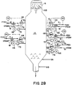
- FIG. 2B shows the reaction portion of the fluid coking and gasification unit in isolation from the heater and gasifier portion and in conjunction with certain process control instrumentation and signals.
- the control system and equipment are in itself conventional, as will be readily appreciated by those skilled in the art and, therefore, are shown only schematically.
- the numbers in FIG. 2B which are less than or equal to 52 are the same as the numbers in FIG. 1 and correspond to the same parts.
- this embodiment actually employs a plurality of feed injectors at each level.
- a flow controller 64 can be cascaded to a feed injector controller 66.
- the flow controller 64 can be cascaded to the differential pressure controller 68, which in turn is cascaded to the same feed injector controller 66 to maintain a target level of atomization.
- the differential pressure controller 68 measures the pressure drop across a portion of the feed injector, suitably the difference between the pressure, as measured by line 70, within the reactor just outside the nozzle tip of the feed injector, and the pressure, as measured by line 72, at a point within the injector just prior to the nozzle throat section that is varied, as explained below with respect to FIG. 3.
- the pressure controller includes a comparator for measuring the difference with a target set point, typically 100 to 150 psi.
- a flow monitoring device 63 measures in real time, the flow rate of feed in the conduit leading to the feed injectors, the signal based thereon being sent via line 74.
- An acoustic measuring device can be employed for this purpose.
- conventional analytical instrumentation can be employed. For example, the API gravity or refractive index may be measured. Feed composition and/or properties may be measured with infrared, ultraviolet, or mass spectroscopy. High pressure liquid chromatography may be employed to separate components of the feed.
- the controller 64 suitably includes a comparator to compare the measured flow rate, typically in units of kilobarrele per day (kB/D), to a set point.
- a signal based on the calculated flow rate or difference from set point can, as mentioned above, be cascaded either directly to the injector controller 66 or in a layered hierarchy to the pressure controller 68 which in turn is cascaded to the injector controller 66.
- the injector controller 66 is used to preferably individually adjust the pressure drop across the feed injectors.
- an actuator 78 is employed to vary the position of suitable atomization adjusting means (not shown).
- a movable member is employed to vary the cross-sectional flow area of a throat section of the feed injector and, thereby, the pressure drop.
- Steam via line 81 is introduced into the feed injector for admixture with the feed oil.
- FIG. 3 a typical embodiment of an reactor feed injector according to the present invention is shown, generally designated 99.
- This injector comprises at one end a nozzle tip 102.
- a fixed throat nozzle geometry is shown, it being understood that various nozzle geometries are quite possible.
- the feed injector is connected to wall 103 of the reactor by what is termed a "thermal sleeve" arrangement 104.
- the feed injector assembly is an integral part of the reactor system.
- Other mechanical attachment arrangements will be familiar to those skilled in the art.
- a feed injector nozzle atomization adjustment assembly comprising a shaft 105 and a lead portion or adjusting means 106, is shown in greater detail in FIG. 4.
- An end tip portion 108 of this adjusting means 106 is designed to function within the converging fan tip nozzle 102. Modulation and/or positioning of the end tip portion 108 within the nozzle tip 102 will change the flow area and influence the atomization achieved by the nozzle tip 102.
- a preferred addition to the basic design of the variable throat feed injector is to include premixers 107 and 109 in close proximity to the nozzle insert tip 106. The premixers enhance the atomization, particularly the spray pattern, achieved by the variable throat feed injector.
- the embodiment of a reactor feed injector assembly shown in FIG. 3 represents a minimum stroke design.
- the two premixers 107 and 109 are staggered on a 45° offset and act as static mixers, slug/bubble breakers, fluid vibration dampeners and radial flow enhancers. From a fluid flow perspective, they impart a radial or swirling moment to the otherwise axial flow. This enhances the atomization achieved by the nozzle. If the flow regime of the fluid in the process pipe leading to the feed injector should happen to fall into an unattractive regime, such as slug flow, the premixers will serve as slug/bubble breakers and help supply a more homogeneous fluid phase mixture immediately upstream of the variable throat nozzle. This will also help enhance the atomization achieved by the nozzle.
- the premixers 107 and 109 also assist in alignment of the shaft 105 and atomization adjusting means 106 within the nozzle 102 and process piping 111.
- the details of a premixer are shown in cross-section in FIG. 5, wherein it is seen that spokes 112 radially emanate from shaft 105 and join a circular rim 113.
- a mixture of steam and oil is introduced upstream of the nozzle tip 102 through a steam oil fluid inlet 114.
- an atomization enhancement medium such as steam to help assist in oil atomization, although other gases could be used.
- the variable throat feed injector could operate with oil-only feed, in a mode to pressure atomize/spray oil without steam being used.
- the atomization enhancement medium could alternatively be introduced into the reactor through separate connections.
- a steam/oil mixture is formed upstream of the nozzle by flow controlling the steam/oil ratio.
- the steam/oil ratio will be set based on oil properties and other process considerations.
- the oil phase may be partially vaporized as a result of preheating.
- the fluid mixture being supplied to the feed injector assembly will usually consist of a gas phase, a liquid oil phase and possibly a vapor oil phase.
- an isolation valve 115 between flanges 116 and 118 may be used as part of the feed injector assembly to allow for onstream maintenance of the system.
- This isolation valve is usually a gate valve, although other valve types such as a ball valve may be used.
- the atomization adjusting means assembly for the nozzle can be retracted, the isolation valve closed and the assembly removed as required for on-stream maintenance. For example, if feed type and chemistry should cause undesirable coking or partial plugging of the nozzle inside, the nozzle insert shaft assembly can be removed and subjected to onstream cleaning.
- a nozzle maintenance receiver pipe section 117 suitably a spool section of piping, is provided between the isolation valve 115 and flange 120.
- a spool section 119 holding a conventional packing gland allows for modulation of a throat insert employed as an atomization adjusting means.
- a low leak design is preferred, although various packing gland designs are acceptable.
- This spool section also allows for on-stream cleaning and maintenance of the nozzle atomization adjustment assembly. It will be appreciated that simplified injector assembly designs are optional, if on-stream maintenance or cleaning is not a concern.
- a suitable mechanical positioning means is exemplified by actuator assembly 221, which provides for the mechanical movement, modulation and stroke control of the nozzle atomization adjustment assembly and shaft. Control of the relative position of the nozzle atomization adjustment assembly relative to the nozzle tip 102 influences the atomization and/or spray pattern from the nozzle.
- actuator assembly 221 which provides for the mechanical movement, modulation and stroke control of the nozzle atomization adjustment assembly and shaft. Control of the relative position of the nozzle atomization adjustment assembly relative to the nozzle tip 102 influences the atomization and/or spray pattern from the nozzle.
- a pneumatic actuator with a manual override feature hand wheel operator
- Other actuator configurations are also acceptable, including a hydraulic actuator or motor-driven actuator. The actuator is capable of receiving control instructions from other instruments and controllers and moving the position of the atomization adjusting means based on these control instructions.
- pneumatic actuators will be preferred over hydraulic actuators because of relative cost, and pneumatic or hydraulic actuators preferred over other types because of reliability. However, unit specific factors may influence actuator selection.
- Various shaft coupling designs are acceptable.
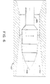
- FIG. 6 shows in greater detail nozzle adjustment assembly 100 (without premixers), positioned at the distal end of shaft 105 and inserted into fan nozzle 102.
- a tip portion 108 of the nozzle adjustment adjusting means 106 is shown at its estimated maximum insertion point.
- FIG. 7 shows a graph, for a typical variable throat nozzle, wherein the flow area is plotted against the percent stroke of the shaft used to move the nozzle atomization adjustment assembly by its actuator.
- FIG. 8 shows in detail an installation of a typical feed injector attached to the wall of a reactor riser of the reactor.
- a similar type of installation is used for the reactor fluid bed portion of the reactor.
- the fluidized regenerated solid particles will be rising, as shown in FIG. 8, and in the latter case, the particles will be descending, and the shapes of the wall may differ, as will be appreciated by those skilled in the art.
- the nozzle tip portion 110 is shown positioned at a typical angle of 20 degrees to the vertical.
- the feed injector is shown in cross-section transversing, in the FIG.
- a conical segment shaped wall 230 section which itself is at a 30 degree angle from the vertical, between an upper relatively larger diameter cylindrical vertical wall portion 232 and a lower relatively smaller diameter cylindrical vertical wall portion 234 of the riser.
- Different attachment angles and orientation angles may be used depending on the specific unit and type of injector.
- the installation of the injector is conventional and utilizes a pipe cap 235 and castable lining 236 beneath the metal walls of the reactor apparatus.
- a kaowool pad plate 238 surrounds the circumference of the feed injector where it pierces the riser wall. Welding at appropriate edges renders the connection airtight.
- Other mechanical attachment arrangements known to those skilled in the art, are suitable.
- This example illustrates tests for collecting data on atomization associated with various nozzle configurations used for feed injection in a fluid catalytic cracking process.
- a similar experimental procedure could be used to generate information specific to a fluid coking (with gasification) process.
- Fine droplets and a wide angle spray are expected to provide more rapid and uniform catalyst/oil mixing in the riser and improve the FCCU operation over the existing nozzles.
- the approach taken in these tests was to conduct cold model tests to examine the effects of liquid viscosity and vapor/liquid flow rates on droplet size, spray dispersion angle, and nozzle pressure drop. Droplet sizes of the sprays were measured with a Laser Doppler Anemometer (LDA). Nitrogen and water/glycerine solutions were used to simulate steam-oil feed. Correlations for predicting the mean droplet size and the pressure drop for a nozzle was developed for use in designing and controlling feed injectors according to the present invention.
- LDA Laser Doppler Anemometer
- Kim and Marshall covered the range of gas-liquid relative velocity from 250 ft/sec to sonic velocity, viscosity 1 to 50 cp, and gas-liquid mass ratio 0.06 to 40.
- the operating ranges of this test program were relative velocity of 200 to 700 ft/sec, viscosity 1.3 to 2.6 cp, and gas-liquid mass ratio from 0.002 to 0.008.
- Kim and Marshall drop-size correlations for convergent-type pneumatic nozzles were obtained for the following ranges: drop-size, 6 to 350 ⁇ m mass medium diameter; mass flow ratio, 0.06 to 40; relative velocity, 250 ft/sec to sonic velocity, and viscosity 1 to 50 cp.
- X ⁇ v s 0.83 X ⁇ m
- X ⁇ m Mass medium diameter
- ⁇ m X ⁇ v s sauter mean diameter
- ⁇ m ⁇ Surface tension
- dynes/ ⁇ m ⁇ 1 Liquid viscosity
- cp ⁇ a, ⁇ 1 Gas and liquid densities
- 1b/ft3 A Area
- ft2 V rel Gas to liquid relative velocity
- ft/sec M a ,M1 Gas to liquid mass flowrates
- the experimental set-up consisted of a chamber (3 feet square and 6 feet long) equipped with light and viewing windows.
- the nozzle was mounted at one end of the rig and sprayed in horizontally.
- a screen at the far end of the rig was used to trap the spray.
- a liquid feed mixing tank was used to blend glycerine with water to provide the desired viscosity.
- Still pictures were taken to determine the spray angle and the Laser Doppler Anemometer (LDA) was used to measure drop size.
- LDA Laser Doppler Anemometer
- the LDA technique for sizing spherical droplets is based on the measurement of the relative phase shift that occurs when two light waves pass through the droplets on different paths. By measuring the visibility or amplitude modulation of the interference pattern formed by the scattered light and collected over a finite collecting operation, adequate information to size the droplete can be obtained.
- the hardware system comprises the following pieces of equipment: transmitter, receiver, visibility processor, data management system, keyboard, Krohn-hite filter, and Anadex printer. The detailed descriptions of these components are given in "Operation Guide for Droplet Sizing Interferometer,” by Spectron Development Laboratories, Inc., SDL No. 82-51025, Costa Mesa, Califomia (1982).
- the function of the transmitter is to project two coherent laser beams into a chosen test space where they may be moving droplets.
- the droplets scatter light from the fringe pattern caused by the crossing beams and the frequency and modulation yield the velocity and size of the measured droplets.
- the "permanent" alignments, which require more care, need only be touched very rarely, if at all.
- the transmitter contains a Spectra-Physics Model Number 107 DEM Helium Neon Laser, laser power supply, steering mirrors, a telescopic beam expander, a half wave plate, a beam steering prism, a 50% beamsplitter and interchangeable output optics.
- the receiver is essentially a telescope with a photomultiplier to collect light from the focal point, at which there is an interchangeable pinhole.
- the positioning of the entire assembly is so as to align it approximately with the transmitted probe volume.
- the receiver collects light that has been scattered from anything within the illuminated sample volume and directs it on to the cathode of the photomultiplier.
- the Visibility and Doppler Signed Processor is a microprocessor which produces particle size information from optical data transmitted from the receiver.
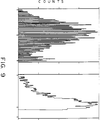
- FIG. 9 illustrates a typical droplet size distribution and a droplet velocity distribution.
- the output also includes linear mean diameter, surface mean diameter, volume mean diameter, sauter mean diameter, and droplet mean velocity.
- the distribution of drop sizes with nozzle no. 3 appear to be wide and bimodal.
- a complete first mode and part of the second mode were recorded in the sprays when the liquid flow rate was lowest at 10 gpm as in Runs 11 and 16.
- the base case liquid rate scaled down from a commercial FCCU is 20 gpm. This indicates that spray drop size can be reduced by lowering the liquid feed rate in the commercial FCCU when using a fan nozzle. Higher liquid viscosity gave larger drops as indicated by the drop size data with 1.3 cp (Runs 7, 8, 11) and 2.6 cp (Runs 12, 13, 16) liquids.
- the spray dispersion angles obtained from pictures with nozzle no. 3 were in the range of 80° to 110°, while those with nozzle no. 2 were between 25° and 40°.
- the spray angles with both nozzles were wider with higher gas/liquid ratios.
- the effect of liquid viscosity on ⁇ P was not noticeable in the narrow viscosity range of 1.3 to 2.6 cp.
- This example illustrates a flow control scheme for an fluid coking with gasification process unit according to the present invention.
- the description was written for application to a particular fluid coking (with gasification) unit, application to other fluid hydrocarbon conversion and cracking units will be appreciated by those skilled in the art.
- the following information in Tables 2, 3, and 4 below are used in the control scheme. (Units of klb/hr, °F, psi, and psig are obtained by calculation. Instrument Tag ID numbers for a particular plant are shown.) Ten feed injectors are assumed to be in service for purposes of illustration in this example. Unit specific conditions would dictate the actual number of feed injectors in service.
- variable XTONAREA is the total nozzle flow area, sq. ft. Individual position of the nozzle insert in each nozzle will allow the flow area in the throat to be calculated for the nozzle geometry. The total flow area available is then calculated based on the number of active nozzles in service.
- the throat velocity is compared to the sonic velocity. If the throat velocity is greater than 65% of the sonic velocity, then the sonic flow pressure drop equation is used to calculate a flow coefficient ("CF"). If the throat velocity is less than 65% of sonic, the sub-sonic flow equation is used to calculate a flow coefficient.
- Sub-sonic "CF" is defined as follows:
- a flow control operating mode will now be described, using the information provided above.
- a total feed flow controller designated F-2004-RC, will reset individual feed injector nozzle controllers to open or close the available flow area to allow more or less total feed to pass into the reactor.
- the flow coefficient parameter "CF" will be monitored in an open loop fashion to ensure that a good atomization region is being maintained. Typically the operator would manipulate the injection steam rate as a means of maintaining a target "CF”.
- the control computer calculated value for the flow coefficient "CF" is a more direct indication of the performance of the feed injector atomization.
- the process feed injector pressure drop reading is a gross indication of feed injector atomization, but many process factors can and will influence this reading.
- ten feed injector nozzles used in this example may be ramped open or closed by moving opposing pairs of nozzles as a unit.
- the pairings would typically be as follows: A/F, B/G, C/H, D/I, and E/J).
- each pair of injectors would be moved a maximum of about 10% stroke at a time in response to feed rate changes. This 10% increment corresponds to about 2.7% of the total nozzle throat area being manipulated at one time.
- Table 5 below illustrates a typical sequential flow area change using this technique:
- Table 5 above illustrates how a very precise flow area control can be maintained and manipulated to achieve the desired level of feed atomization.
- the above case is an illustration of a controlled ramping closed of the feed injectors, caused by either a change in total feed rate to the unit or a change in the target amount of injection steam being used.
- a reverse sequence would be used.
- the control computer application program could be constructed in several different forms.
- the total feed flow controller, F-2004-RC could be cascaded directly to the feed injector actuators, H-2099-IC (A to J), or in a layered hierarchy with F-2004-RC cascaded to P-2099-dRC (A to J) which in turn could be cascaded to the individual feed injector actuators, H-2099-IC (A to J).
- Having individual actuator controllers and PdRC instrumentation on each feed injector provides flexibility for on stream maintenance and control loop tuning of the feed injector system. Lower cost configurations are possible with fewer instruments, and would represent a simplified version of the configuration detailed above.
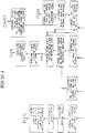
- FIG. 10 (parts A and B) is a schematic illustrating the basic structure of a typical control computer application program to vary feed injector throat area based on total reactor feed processing objectives. It is based on a ten variable throat feed injector system with a PdRC controller cascaded to the injector actuator, HIC: P-2099-dRC A cascaded to H-2099-IC A, etc. Operator-supplied set points for P-2099-dRC (A to J) are based on a unit specific run plan to initialize the system. This set point is consistent with a target spray pattern. The calculated flow coefficient "CF" will be calculated in a real time frame. This "CF" will be used as an index of feed atomization.
- the control scheme detailed above is based on a "single stage" reactor configuration where the oil feed is introduced at a specific point along the length of the reactor. This scheme could also be applied to "multi-stage” reactor configurations where the oil feed is introduced at several points along the length of the reactor. When applied to a "multi-stage” configuration, various hybrid control configurations become possible.
- the matrix in Table 6 below illustrates how four distinct control schemes could optimally be applied to a two stage reactor configuration. For more than two stages, a much larger matrix is appropriate.
- a two stage system is viewed as a reasonable commercial configuration with three stages being a possible commercial "stretch case" depending on economics.
- the four distinct control schemes might typically be defined as follows: (1) total flow control, (2) reactor temperature control, (3) carbon and heat balance control, and (4) yield selectivity/quality control.
Landscapes
- Chemical & Material Sciences (AREA)
- Engineering & Computer Science (AREA)
- Chemical Kinetics & Catalysis (AREA)
- Oil, Petroleum & Natural Gas (AREA)
- Organic Chemistry (AREA)
- General Chemical & Material Sciences (AREA)
- Combustion & Propulsion (AREA)
- Production Of Liquid Hydrocarbon Mixture For Refining Petroleum (AREA)
Applications Claiming Priority (2)
| Application Number | Priority Date | Filing Date | Title |
|---|---|---|---|
| US54847490A | 1990-07-03 | 1990-07-03 | |
| US548474 | 1990-07-03 |
Publications (2)
| Publication Number | Publication Date |
|---|---|
| EP0465157A1 true EP0465157A1 (de) | 1992-01-08 |
| EP0465157B1 EP0465157B1 (de) | 1995-07-19 |
Family
ID=24188997
Family Applications (1)
| Application Number | Title | Priority Date | Filing Date |
|---|---|---|---|
| EP19910305878 Expired - Lifetime EP0465157B1 (de) | 1990-07-03 | 1991-06-28 | Fluidbett-Verkokungsapparat und Kontrollverfahren dafür |
Country Status (4)
| Country | Link |
|---|---|
| EP (1) | EP0465157B1 (de) |
| JP (1) | JPH04226591A (de) |
| CA (1) | CA2043454A1 (de) |
| DE (1) | DE69111318T2 (de) |
Cited By (1)
| Publication number | Priority date | Publication date | Assignee | Title |
|---|---|---|---|---|
| WO2022010822A1 (en) * | 2020-07-06 | 2022-01-13 | Sabic Global Technologies B.V. | Method and reactor for conversion of hydrocarbons |
Citations (6)
| Publication number | Priority date | Publication date | Assignee | Title |
|---|---|---|---|---|
| US4434049A (en) * | 1982-03-17 | 1984-02-28 | Dean Robert R | Residual oil feed process for fluid catalyst cracking |
| US4575414A (en) * | 1984-08-29 | 1986-03-11 | Phillips Petroleum Company | Method for mixing of fluidized solids and fluids |
| EP0208609A1 (de) * | 1985-07-10 | 1987-01-14 | Total Raffinage Distribution S.A. | Verfahren und Einrichtung für das katalytische Kracken von Kohlenwasserstoffen mit Kontrolle der Reaktionstemperatur |
| EP0227864A1 (de) * | 1984-05-30 | 1987-07-08 | Mobil Oil Corporation | Einrichtung zum Einspritzen von FCC-Einsätzen und FCC-Verfahren |
| US4793913A (en) * | 1983-02-04 | 1988-12-27 | Chevron Research Company | Method for liquid feed dispersion in fluid catalytic cracking systems |
| EP0444860A1 (de) * | 1990-02-27 | 1991-09-04 | Exxon Research And Engineering Company | Katalytische Wirbelschicht-Krackanlage mit verbessertem Einsatzeinspritzsystem |
-
1991
- 1991-05-29 CA CA 2043454 patent/CA2043454A1/en not_active Abandoned
- 1991-06-28 DE DE1991611318 patent/DE69111318T2/de not_active Expired - Fee Related
- 1991-06-28 EP EP19910305878 patent/EP0465157B1/de not_active Expired - Lifetime
- 1991-07-03 JP JP16314491A patent/JPH04226591A/ja active Pending
Patent Citations (6)
| Publication number | Priority date | Publication date | Assignee | Title |
|---|---|---|---|---|
| US4434049A (en) * | 1982-03-17 | 1984-02-28 | Dean Robert R | Residual oil feed process for fluid catalyst cracking |
| US4793913A (en) * | 1983-02-04 | 1988-12-27 | Chevron Research Company | Method for liquid feed dispersion in fluid catalytic cracking systems |
| EP0227864A1 (de) * | 1984-05-30 | 1987-07-08 | Mobil Oil Corporation | Einrichtung zum Einspritzen von FCC-Einsätzen und FCC-Verfahren |
| US4575414A (en) * | 1984-08-29 | 1986-03-11 | Phillips Petroleum Company | Method for mixing of fluidized solids and fluids |
| EP0208609A1 (de) * | 1985-07-10 | 1987-01-14 | Total Raffinage Distribution S.A. | Verfahren und Einrichtung für das katalytische Kracken von Kohlenwasserstoffen mit Kontrolle der Reaktionstemperatur |
| EP0444860A1 (de) * | 1990-02-27 | 1991-09-04 | Exxon Research And Engineering Company | Katalytische Wirbelschicht-Krackanlage mit verbessertem Einsatzeinspritzsystem |
Cited By (2)
| Publication number | Priority date | Publication date | Assignee | Title |
|---|---|---|---|---|
| WO2022010822A1 (en) * | 2020-07-06 | 2022-01-13 | Sabic Global Technologies B.V. | Method and reactor for conversion of hydrocarbons |
| US20230256406A1 (en) * | 2020-07-06 | 2023-08-17 | Sabic Global Technologies B.V. | Method and reactor for conversion of hydrocarbons |
Also Published As
| Publication number | Publication date |
|---|---|
| JPH04226591A (ja) | 1992-08-17 |
| DE69111318D1 (de) | 1995-08-24 |
| EP0465157B1 (de) | 1995-07-19 |
| DE69111318T2 (de) | 1996-02-08 |
| CA2043454A1 (en) | 1992-01-04 |
Similar Documents
| Publication | Publication Date | Title |
|---|---|---|
| US5188805A (en) | Controlling temperature in a fluid hydrocarbon conversion and cracking apparatus and process comprising a novel feed injection system | |
| US5298155A (en) | Controlling yields and selectivity in a fluid catalytic cracker unit | |
| EP0454416B1 (de) | Einsatzzuführung für eine katalytische Krackanlage | |
| US6069012A (en) | Versatile fluidized bed reactor | |
| US4985136A (en) | Ultra-short contact time fluidized catalytic cracking process | |
| EP0593171B1 (de) | Verfahren zur Zerstäubung von Beschickung in einem katalytischen Wirbelschicht-Krackverfahren | |
| CA2574370C (en) | Feed injector | |
| US5554341A (en) | Feed zone performance for a cat cracker | |
| EP0108199B1 (de) | Methode und Mittel um geschäumte Rückstandsöle mit fluidisierten festen Teilchen in Kontakt zu bringen | |
| CN101094906A (zh) | Fcc进料注射系统 | |
| EP0444859B1 (de) | Verfahren und Einrichtung zur Steuerung einer katalytischen Wirbelschicht-Krackanlage | |
| EP0465161B1 (de) | Methode zur Regelung der Temperatur, der Ausbeute und der Selektivität von fluidisierter Kohlenwasserstoffumwandlung und Krackapparatur und -verfahren | |
| Gauthier et al. | FCC: fluidization phenomena and technologies | |
| EP0465157B1 (de) | Fluidbett-Verkokungsapparat und Kontrollverfahren dafür | |
| EP0444860B1 (de) | Katalytische Wirbelschicht-Krackanlage mit verbessertem Einsatzeinspritzsystem | |
| US4824557A (en) | Process for mixing cracking catalyst with a fluid hydrocarbon | |
| US4729825A (en) | Method and apparatus for contacting feed materials with fluidized solids | |
| US4778658A (en) | Method and apparatus for contacting fluid feed materials with fluidized solids | |
| AU2005323169B2 (en) | FCC feed injection for atomizing feed | |
| US4808382A (en) | Process for mixing cracking catalyst with a fluid hydrocarbon | |
| US5160706A (en) | Process for the catalytic cracking of a hydrocarbon oil | |
| US4624836A (en) | Apparatus and process for mixing cracking catalyst with a fluid hydrocarbon | |
| CA2217889A1 (en) | Conditions of operation during coking which leads to higher yields of valuable liquid products |
Legal Events
| Date | Code | Title | Description |
|---|---|---|---|
| PUAI | Public reference made under article 153(3) epc to a published international application that has entered the european phase |
Free format text: ORIGINAL CODE: 0009012 |
|
| AK | Designated contracting states |
Kind code of ref document: A1 Designated state(s): BE DE FR GB IT NL |
|
| 17P | Request for examination filed |
Effective date: 19920623 |
|
| 17Q | First examination report despatched |
Effective date: 19930413 |
|
| GRAA | (expected) grant |
Free format text: ORIGINAL CODE: 0009210 |
|
| AK | Designated contracting states |
Kind code of ref document: B1 Designated state(s): BE DE FR GB IT NL |
|
| REF | Corresponds to: |
Ref document number: 69111318 Country of ref document: DE Date of ref document: 19950824 |
|
| ET | Fr: translation filed | ||
| ITF | It: translation for a ep patent filed | ||
| PLBE | No opposition filed within time limit |
Free format text: ORIGINAL CODE: 0009261 |
|
| STAA | Information on the status of an ep patent application or granted ep patent |
Free format text: STATUS: NO OPPOSITION FILED WITHIN TIME LIMIT |
|
| PGFP | Annual fee paid to national office [announced via postgrant information from national office to epo] |
Ref country code: GB Payment date: 19960530 Year of fee payment: 6 |
|
| PGFP | Annual fee paid to national office [announced via postgrant information from national office to epo] |
Ref country code: FR Payment date: 19960614 Year of fee payment: 6 |
|
| 26N | No opposition filed | ||
| PGFP | Annual fee paid to national office [announced via postgrant information from national office to epo] |
Ref country code: DE Payment date: 19960816 Year of fee payment: 6 |
|
| PG25 | Lapsed in a contracting state [announced via postgrant information from national office to epo] |
Ref country code: GB Free format text: LAPSE BECAUSE OF NON-PAYMENT OF DUE FEES Effective date: 19970628 |
|
| GBPC | Gb: european patent ceased through non-payment of renewal fee |
Effective date: 19970628 |
|
| PG25 | Lapsed in a contracting state [announced via postgrant information from national office to epo] |
Ref country code: FR Free format text: LAPSE BECAUSE OF NON-PAYMENT OF DUE FEES Effective date: 19980227 |
|
| PG25 | Lapsed in a contracting state [announced via postgrant information from national office to epo] |
Ref country code: DE Free format text: LAPSE BECAUSE OF NON-PAYMENT OF DUE FEES Effective date: 19980303 |
|
| REG | Reference to a national code |
Ref country code: FR Ref legal event code: ST |
|
| REG | Reference to a national code |
Ref country code: FR Ref legal event code: ST |
|
| PGFP | Annual fee paid to national office [announced via postgrant information from national office to epo] |
Ref country code: NL Payment date: 20030513 Year of fee payment: 13 |
|
| PGFP | Annual fee paid to national office [announced via postgrant information from national office to epo] |
Ref country code: BE Payment date: 20030715 Year of fee payment: 13 |
|
| PG25 | Lapsed in a contracting state [announced via postgrant information from national office to epo] |
Ref country code: BE Free format text: LAPSE BECAUSE OF NON-PAYMENT OF DUE FEES Effective date: 20040630 |
|
| BERE | Be: lapsed |
Owner name: *EXXON RESEARCH AND ENGINEERING CY Effective date: 20040630 |
|
| PG25 | Lapsed in a contracting state [announced via postgrant information from national office to epo] |
Ref country code: NL Free format text: LAPSE BECAUSE OF NON-PAYMENT OF DUE FEES Effective date: 20050101 |
|
| NLV4 | Nl: lapsed or anulled due to non-payment of the annual fee |
Effective date: 20050101 |
|
| PG25 | Lapsed in a contracting state [announced via postgrant information from national office to epo] |
Ref country code: IT Free format text: LAPSE BECAUSE OF NON-PAYMENT OF DUE FEES;WARNING: LAPSES OF ITALIAN PATENTS WITH EFFECTIVE DATE BEFORE 2007 MAY HAVE OCCURRED AT ANY TIME BEFORE 2007. THE CORRECT EFFECTIVE DATE MAY BE DIFFERENT FROM THE ONE RECORDED. Effective date: 20050628 |