EP0465215B1 - Tragbarer Kopierer - Google Patents
Tragbarer Kopierer Download PDFInfo
- Publication number
- EP0465215B1 EP0465215B1 EP91305987A EP91305987A EP0465215B1 EP 0465215 B1 EP0465215 B1 EP 0465215B1 EP 91305987 A EP91305987 A EP 91305987A EP 91305987 A EP91305987 A EP 91305987A EP 0465215 B1 EP0465215 B1 EP 0465215B1
- Authority
- EP
- European Patent Office
- Prior art keywords
- copier
- platen
- accessory
- rails
- document
- Prior art date
- Legal status (The legal status is an assumption and is not a legal conclusion. Google has not performed a legal analysis and makes no representation as to the accuracy of the status listed.)
- Expired - Lifetime
Links
Images






Classifications
-
- H—ELECTRICITY
- H04—ELECTRIC COMMUNICATION TECHNIQUE
- H04N—PICTORIAL COMMUNICATION, e.g. TELEVISION
- H04N1/00—Scanning, transmission or reproduction of documents or the like, e.g. facsimile transmission; Details thereof
- H04N1/04—Scanning arrangements, i.e. arrangements for the displacement of active reading or reproducing elements relative to the original or reproducing medium, or vice versa
- H04N1/10—Scanning arrangements, i.e. arrangements for the displacement of active reading or reproducing elements relative to the original or reproducing medium, or vice versa using flat picture-bearing surfaces
- H04N1/1013—Scanning arrangements, i.e. arrangements for the displacement of active reading or reproducing elements relative to the original or reproducing medium, or vice versa using flat picture-bearing surfaces with sub-scanning by translatory movement of at least a part of the main-scanning components
- H04N1/1017—Scanning arrangements, i.e. arrangements for the displacement of active reading or reproducing elements relative to the original or reproducing medium, or vice versa using flat picture-bearing surfaces with sub-scanning by translatory movement of at least a part of the main-scanning components the main-scanning components remaining positionally invariant with respect to one another in the sub-scanning direction
-
- H—ELECTRICITY
- H04—ELECTRIC COMMUNICATION TECHNIQUE
- H04N—PICTORIAL COMMUNICATION, e.g. TELEVISION
- H04N1/00—Scanning, transmission or reproduction of documents or the like, e.g. facsimile transmission; Details thereof
- H04N1/04—Scanning arrangements, i.e. arrangements for the displacement of active reading or reproducing elements relative to the original or reproducing medium, or vice versa
- H04N1/19—Scanning arrangements, i.e. arrangements for the displacement of active reading or reproducing elements relative to the original or reproducing medium, or vice versa using multi-element arrays
- H04N1/191—Scanning arrangements, i.e. arrangements for the displacement of active reading or reproducing elements relative to the original or reproducing medium, or vice versa using multi-element arrays the array comprising a one-dimensional [1D] array
- H04N1/1911—Simultaneously or substantially simultaneously scanning picture elements on more than one main scanning line, e.g. scanning in swaths
-
- H—ELECTRICITY
- H04—ELECTRIC COMMUNICATION TECHNIQUE
- H04N—PICTORIAL COMMUNICATION, e.g. TELEVISION
- H04N2201/00—Indexing scheme relating to scanning, transmission or reproduction of documents or the like, and to details thereof
- H04N2201/04—Scanning arrangements
- H04N2201/0402—Arrangements not specific to a particular one of the scanning methods covered by groups H04N1/04 - H04N1/207
- H04N2201/0466—Selectively scanning in one or the other of two opposite directions, e.g. in the forward or the reverse direction
- H04N2201/0468—Scanning in both of the two directions, e.g. during the forward and return movements
Definitions
- the present invention relates to a very low cost portable copier. More particularly it is directed to a detachable portable platen accessory for use with a portable copier which will enable copying from books and magazines.
- copies of original documents have been produced by a xerographic process wherein the original document to be copied is placed on a transparent platen, either by hand or automatically through the use of a document handler, and the original document illuminated by a relatively high intensity light.
- Image rays reflected from the illuminated document are focused by a suitable optical system on to a previously-charged photoconductor, the image light rays functioning to discharge the photoconductor in accordance with the irrage content of the original to produce an electrostatic latent image of the original on the photoconductor.
- the electrostatic latent image so produced is thereafter developed by a suitable developer material, commonly referred to as 'toner', and the developed image transferred to a sheet of copy paper brought forward by a suitable feeder.
- the transferred image is thereafter fixed to the copy paper by fusing to provide a permanent copy while the photoconductor is cleaned of residual developer preparatory to recharging.
- electronic imaging where, in contrast to the aforedescribed xerographic system, the image of the document original is converted to electrical signals or pixels and these signals, which may be processed, transmitted over long distances, and/or stored, are used to produce one or more copies.
- the optical system rather than focusing the light image onto a photoreceptor for purposes of discharging a charged surface prior to xerographic development, the optical system focuses the image rays reflected from the document original on to the image-reading array which serves to convert the image rays to electrical signals.
- These signals are used to create an image by some means, such as those operating a laser beam to discharge a xerographic photoreceptor, or those operating some direct-marking system, such as an ink jet or thermal transfer printing system.
- US-A-4,496,984 and US-A-4,583,126 disclose an input/output scanner for simultaneously reading a document and writing a copy.
- the document and copy sheet are fed in back-to-back relation to the read/write station.
- a monolithic full-width read array reads each line in two steps, to improve resolution.
- the writing array consists of rows of ink jet nozzles, of which the number and disposition is in direct correspondence to the sensors of the read bar.
- US-A-4,424,524 discloses a full-width read/write LED array for scanning a document in the read mode or exposing the photoreceptor in the write mode.
- An optical,fiber lens array is used for focusing the full-width LED array on the document or photoreceptor.
- a difficulty with these known systems is the complexity and cost of separate components,such as the complex optics, photoreceptor and developer in a typical xerographic process.
- Such a system also has a significant cost penalty associated with components such as the monolithic fill-width read array.
- the present application is directed to a solution to the difficulty of making copies from books and magazines and in particular is directed to providing a detachable portable platen for use with a portable copier which will enable copying from books and magazines.
- US-A-3,588,244 discloses a book copier attachment for a photocopy machine which includes a frame and a carrier means for movement within the frame.
- the attachment is used on a copier having a sheet copying position and a book copying position.
- US-A-3,445,164 discloses a portable copying machine having a rigid member having a surface of a size coextensive with the copy paper.
- the rigid member can be a platform on which copy paper is laid, or a transparent member placed upon the paper in which internal light reflections are conducted.
- the copier is capable of copying large objects such as maps and books.
- US-A-3,132,810 discloses a photographic illumination device which may be used to copy pages from a book as well as sheets of paper. See Figs. 3-4 which show light box 24, wedge attachment 16 for supporting and allowing light to expose photosensitive paper 12, and original 10, which may be a sheet or a book.
- the present invention is directed to a platen accessory for a portable copier not having a platen which has a pair of parallel copier transport rails mounted to a transparent document support member.
- the rails have a drive surface for engagement with a drive mechanism on the portable copier to transport the copier along the drive surface.
- the present invention provides a copier which is as claimed in the appended claims.
- the drive surface is on the bottom of the transport rails, and the document support member is supported by legs of sufficient length that the portable copier can be freely transported along the drive surface on the bottom of the rails.
- the portable copier is mounted for movement in a pair of parallel grooves, one in each of the parallel transport rails.
- the platen accessory has a longitudinal cover adjacent each of the transport rails to cover portions of the portable copier when inserted therein and to support the portable copier as it is transported along its transport path.
- the cover may be of one piece, or may be of two pieces including a first top cover to cover the top portions of the portable copier to minimize interference with a document on the document support member being reproduced, and further includes copier support member such as rails.
- Reproducing apparatus comprising a portable imaging platen and a self contained portable copier not having a platen.
- the self-contained portable copier includes a scanner carriage adapted for scanning movement and having a read head secured thereto for scanning a document to produce a digital image and a write head secured thereto for printing the digital image on a copy sheet.
- the portable copier is movably mounted on the index rails of the imaging platen and has a drive mechanism for transporting the portable copier along the drive surface of the transport rails.
- the portable copier has inboard and outboard sides adjacent the transport ra:is and is urged into driving engagement with a drive surface of the rails by means of leaf sprirg clips around each of the inboard and outboard sides of the copier which are supported in longitude grooves on the transport rails.
- the portable copier has a biasing means such as a spring-loaded idler roll on each of its inboard and outboard sides to urge it upwardly into driving engagement with the drive surface of the copier transport rails.
- a biasing means such as a spring-loaded idler roll on each of its inboard and outboard sides to urge it upwardly into driving engagement with the drive surface of the copier transport rails.
- the scanner carriage is movably mounted in a copier frame assembly for scanning movement between the inboard and outboard sides of the frame assembly including a copy sheet transport path including means to index a copy sheet in a set copy sheet path in a direction transverse to the scan path and means to index, comprising a pair of synchronously-driven rotatable drive rolls forming a feeding nip with a copy sheet idler roll and an indexing nip with said drive surface of the indexing rails.
- the read head scans a band of information across the document on the document support member and the print head simultaneously prints the same band of informatior across the copy sheet.
- the transport means indexes the copy sheet and the portable copier in their respective paths a distance equal to the width of the band of information before the carriage scans another band of information across the document.
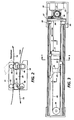
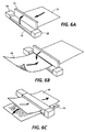
- the copier is generally illustrated as comprising a frame assembly 15 having a maintenance station 12 at one end and a top cover 11 pivotally mounted to the frame assembly.
- the top cover is rotated to an open position as shown in Figure 6A, copy sheet 13 is inserted at the entrance of the copy sheet transport path, and the document 14 is inserted against a registration stop member in the top cover, after which the top cover is closed and the copying sequence begins by the carriage scanning a band across the document.
- the image on the document is digitized by an input digitizing system and a digital image is essentially simultaneously printed by a printing system on the copy sheet.
- the document is indexed to the right as viewed, and the copy sheet is indexed to the left as viewed, to enable the scanner carriage to scan a second band of information in the reverse direction across the document.
- the distance of indexing both the document and the copy sheet is the width of the scanned band.
- the scanner 10 includes a frame assembly 15 composed of a base unit 18 and rails 19 within which scanner carriage 20 is transported along its path.
- the scanner carriage 20 is parked in the maintenance station 12 where it is protected from contamination and maintained in a relatively-constant environment.
- the scanner carriage 20 includes an array of light-emitting diodes 21 mounted on substrate 52 which is typically of ceramic or plastics material, and has a heat sink 54 built into its rear portion.
- Input and control chip 26 and ink jet chip 27 are mounted in the same plane to the same planar substrate 52.
- the document can be scanned with the image being reflected by mirror 22 through half-lens 23 back to the input and control chip, which can essentially simultaneously activate the ink jet chip 27.
- mechanical tolerance requirements can be substantially reduced.
- This configuration also enables the input chip and ink jet chip, and possibly all control chips, to be combined into a single chip.
- This assembly scans or reads document images in the scanned document 14, the area scanned or read being converted to electric image signals, or 'pixels'.
- the image signals generated by the read head are input to a print bar 25, which may be any suitable direct imaging device, such as a thermal transfer head or preferably a thermal ink jet array 27, to write copies of the document in accordance with the image signals onto a suitable substrate or copy sheet 13.
- the number of scanning elements or sensors per unit length that comprise the image read bar 17 determine the initial scanning resolution, while the number of ink jet nozzles 25 per unit length that comprise the print bar 25 determine the resolution of the image copy.
- the number of input scanner elements equals the number of output printing elements.
- scanner carriage 20 which is mounted for forward and backward bi-directional scanning movement in a scanning path along the length of the frame assembly by means of scan stepper motor 32 through gear 31, pulleys 29 and 30, and cable 28 to move the scanner carriage in the rails 19.
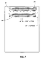
- FIG. 7 The movement of the scan carriage 20 supporting image read assembly 21, 22, 23, 26 and print bar 25 is further illustrated with respect to Figure 7.
- Arrows 33a and 33b illustrate the forward and reverse scan of the carriage 20 across a document and copy sheet, also shown in Figure 2.
- the arrows 68 illustrate that a number of pixels, perpendicular to the direction of movement of scan carriage 22, are both read by the read assembly and printed by the print bar as the carriage scans the document and copy sheet.
- 192 pixels at 12 per mm are read and printed perpendicular to the movement of carriage as it scans.
- arrow 68 represents a band 83 ⁇ m long and 16.25 mm wide which is read and printed. This enables scanning of a band about 16 mm wide.
- the movement of the carriage can be continuous or in discrete steps but, in a preferred embodiment, the 192 pixels are read and printed in increments that are one pixel apart as shown.
- the electronic image of 192 pixels down the sheet are moved into a shift register and then amplified and shifted in reverse order into the print bar to fire the 192 ink jets and thereby create a print of the 192 pixels previously read.
- This sequence is repeated each time the scan carriage has moved a distance of one pixel width. It should be noted that the scanning could also be done with 192 parallel channels, each channel reading and writing a single line of pixels as the carriage sweeps across the page.
- a digital buffer or register could be incorporated to store the read signals initially for printing later after a predetermined or arbitrary period.
- the combined scanner illustrated has multi-mode capability and could be operated independently as a printer modulated by any suitable device providing digital information, operated independently as a scanner to convert source documents to a digital representation, or operated as a facsimile device using the read and print elements when combined with a suitable modem, or operated as a copier by combining the scann and print operations.
- the document and copy sheet are each indexed through the scanner in opposite directions transversely of the scan path through a distance equal to the width of the band scanned by the read head, which is the same as the width of the band printed on the copy sheet by the print head.
- This width can be any width from a minimum of a single pixel line to a maximum of the width of the entire document. In practical terms, however, in order to keep the cost of the read and write components low the width of the band is of the order of a mm to several decades of mm wide. The method for achieving this is illustrated with further reference to FIGS.
- an indexing means is provided at one end of the frame assembly, comprising a pair of synchronously driven rotatable drive rolls 35 forming a feed nip for a document with document feed idler rolls 42 contained within the top cover 11 of the scanner.
- the term'synchronously driven' is intended to define only that the drive rolls 35 are synchronized to each other.
- the drive rolls 35 also form a feed nip for a copy sheet with the copy sheet idler rolls 46 in the copy sheet transport path.
- the drive rolls 35 are driven by index motor 38 through pulley gear 37 and belt 36.
- the scan stepper motor 32 and the index stepper motor 38 are controlled by logic 33, as illustrated in Figure 4.
- the top cover 11 is pivotally mounted to the frame assembly 15, and in particular the base unit 18 pivots about points 41.
- the document feed idler rolls are disengaged from the drive rolls and the registration edge 44 is inserted into the plane of the document transport path, enabling the placement of a document to be copied in the scanner with its lead edge registered and inhibiting transport of the document through the document transport path.
- the copy sheet idler rolls 46 in the base unit are retracted from engagement with the drive rolls 35 by linkage (not shown) when the top cover is raised to the open position.
- registration gates 47 are inserted into the copy sheet transport path to enable manual registration of the copy sheet.
- the circumference of the drive rolls is equal to the width of the band scanned by the scanner carriage to eliminate run out and shaft straightness tolerance defects which otherwise might cause some mis -registration between scan widths.
- the base unit 18 has ink supply 49 connected to the ink jet print head 27 by means of a flexible umbilical ink supply tube 50. While the scanner may have power supplied by conventional connection to domestic mains.
- Figure 1 illustrates a preferred embodiment wherein a rechargeable battery 43 is contained within the top.
- the top cover is closed, thereby engaging the drive roll with the sheets between it and its cooperating idler rolls.
- the copy paper registration fingers are withdrawn, two sensors (not illustrated) detect that both the document and the copy paper have been loaded accordingly, and the logic initiates the copying sequence.
- the scan carriage containing the read and write head disengages from the maintenance station and scans across the document and copy sheet while both remain stationary.
- the document is positioned so that its lead edge coincides with the right-hand pixel of the read head, and the copy paper is positioned so that its lead edge coincides with the left-hand pixel of the print head. This enables the formation of a right reading image in the copy sheet.
- a line of information on the document read on the right extreme of the image read head fires the print head on the extreme lift of the printing array during the scan of the carriage 20.
- This may be illustrated with reference to Figure 5.
- the pixel data received by the input chip at the extreme right of the chip (R) as the carriage 20 moves in the direction into and out of the paper are transmitted and amplified to modulate the print head to fire the print head at the extreme left (L) of the print head.
- This enables the printing of right reading copies with essentially simultaneous reading and writing without information storage.
- the 16.25 mm band being read off the document is immediately printed on to the copy paper. When the first scan is complete, the carriage motion stops.
- Both the document and copy paper are then indexed in a direction transverse to the scann direction the width of the band just.
- This indexing is accomplished by driving the single pair of drive rolls, which engage the document at the 12:00 position with the document feed idler rolls forming a feed nip therebetween, and the copy paper at the 6:00 position with the copy sheet feed idler roll forming a feed nip therebetween.
- the clockwise motion as viewed of the drive rolls through one revolution causes a document to be indexed 16.25 mm to the right, and the copy paper to be indexed 16.25 mm to the left. In this way the second band of the document is moved into a position over the scan carriage, and a second portion of the copy paper is moved to a position under the print head.
- the scan carriage scans across the document and copy paper in the reverse direction from the first scan, again reading the document and immediately printing the copy. This sequence is repeated until the entire document is read and the entire copy is printed, after which time the print head returns to the maintenance station and is parked.
- the index motor is activated to eject the trail edge of the document to the right, and the copy to the left, after which the scanner returns to the dormant state until the top cover is again opened and closed to reinitiate the next copy sequence.
- the platen accessory 71 includes document support member 72, which typically is a transparent imaging platen made from glass or plastics.
- the platen accessory has a pair of spaced parallel copier transport rails 73 running along two sides of the document support member.
- the platen accessory is provided with legs 76 which may be firmly attached to the copier transport rails or may be detachable or pivotally mounted to enable compactness in storage.
- the parallel copier transport rails have grooves 80 along their longitudinal length.
- the portable copier is suspended from the bottom of the platen accessory by means of two leaf spring clamps 81, one of which is wrapped around the inboard side 77 of the portable copier; the other of which is wrapped around the outboard side 78 of the portable copier, and the ends of which are inserted into the grooves 80.
- a document support platform has been substituted for the document transport mechanism whereby the top cover 11 of the portable copier illustrated in Figure 1 may be removed to expose which the top surface of the drive rolls.
- the leaf springs lift the copier in contact with the platen so that the document drive rolls 35 contact the drive surface 74 on the under side of the copier index rails 73.
- a modular LED array 82 and a 45° mirror 83 are added to modify the optical path by moving the focal point to the top surface of the document support member when using the portable platen.
- the top cover 11 of the portable copier is removed, together with the document feed idler rolls 42, the legs on the platen accessory are attached or folded down, it being noted that the legs need to be long enough to provide a clearance between the bottom of the copier and the top of the support table, as illustrated in Figure 10.
- the auxiliary optical module consisting of the second LED array and a second 45° mirror, is snapped or inserted into place.
- the leaf springs are snapped on to the inboard and outboard side of the portable copier, and the ends of the leaf springs are inserted into the grooves 80 in the copier transport rails 73 to suspend the copier below the document support member 72.
- Figures 11A, 11B, 11C, and 11D illustrate the book copying operation.
- a book is placed on the platen 72, and the copying sequence is initiated in Figure 11B by the insertion of a copy sheet 13 into the portable copier 10.
- the scanning carriage 20 completes scanning a band from the book on the platen
- the copier and the copy paper are both indexed to the left as seen in Figure 11C.
- Figure 11D the copier has indexed itself to the left-most position on the platen, and the completed copy 13 extends to the left from the portable copier.
- the portable copier may then be moved to the right-most position, Figure 11A, in preparation for the next copy.
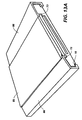
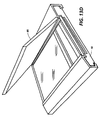
- FIGs 12, 13A, 13B, 13C and 13D wherein an alternative embodiment of the present invention if illustrated.
- This embodiment has the additional advantage that the ends of the portable copier are covered, so that a large document, such as a bound document which may extend over the edge of the document support member when placed on the detachable platen, will not be in interference with the movement of the inboard side or outboard side of the copier, thereby interfering with the indexing accuracy and creating sticking errors.
- a longitudinal support cover 86 may be provided adjacent to each of the parallel copier index rails 73 to enclose the portable copier.
- this longitudinal support cover may be comprised of two sections: a top cover 87, and a foldable mounted side portion cover 89 having copier support rails 88 integral therewith.
- an idler roll 90 in the base of the copier is spring loaded by spring 91 to press against the rails 88 which may be molded into the side cover 89 to create the upward normal force between the drive rolls 35 and a drive surface 74 on the copier index rails 73 adjacent document support member (platen) 72.
- a platen cover 85 can be provided in either embodiment. Typically the platen cover is pivotally mounted for movement between an open position and a closed position, and has a light-reflective surface.
- a portable platen accessory for a portable copier which enables the user to be able to reproduce not only cut sheet documents, but to to copy from books and magazines at remote locations. Further the reproducing apparatus is compact, efficient, and economical.
Landscapes
- Engineering & Computer Science (AREA)
- Multimedia (AREA)
- Signal Processing (AREA)
- Facsimile Scanning Arrangements (AREA)
Claims (12)
- Vorlagenglas-Zusatzeinrichtung (71) für einen tragbaren Kopierer (10) ohne Vorlagenglas, welche umfaßt: ein transparentes Vorlagenglas (72), ein Paar am Vorlagenglas angebrachter paralleler Kopierertransportschienen (73), die die Transportbahn des Kopierers über das Vorlagenglas festlegen und über eine so gestaltete Lauffläche (74) verfügen, daß die Antriebsvorrichtung (35) des tragbaren Kopierers den Kopierer im Eingriff entlang der Lauffläche bewegen kann, sowie eine Vorrichtung (81), die mit dem Paar paralleler Kopierertransportschienen zusammenwirkt und mit denen der tragbare Kopierer abnehmbar an der Vorlagenglas-Zusatzeinrichtung befestigt werden kann.
- Zusatzeinrichtung nach Anspruch 1, wobei sich die Lauffläche (74) an der Unterseite der Schienen (73) befindet und das Vorlagenglas auf Füßen (76) steht, deren Länge die Tiefe des Kopierers übertrifft, so daß der am Vorlagenglas befindliche Kopierer einen Abstand zur Aufstellfläche des Vorlagenglases hat.
- Zusatzeinrichtung nach Anspruch 2, wobei die Füße klappbar an den Schienen angebracht sind.
- Zusatzeinrichtung nach einem der vorangegangenen Ansprüche, die eine lichtreflektierende Abdeckung (85) aufweist, welche klappbar am Vorlagenglas angebracht ist, so daß sie eine geöffnete Stellung, in der das Vorlagenglas freiliegt, und eine geschlossene Stellung hat.
- Zusatzeinrichtung nach einem der vorangegangenen Ansprüche, wobei jede Schiene über eine in Längsrichtung verlaufende Nut (80) verfügt.
- Zusatzeinrichtung nach einem der vorangegangenen Ansprüche, wobei die Befestigungseinrichtung eine Längsverkleidung (81, 89) aufweist, die an jeder Schiene anliegt, Teile des am Vorlagenglas befestigten Kopierers verdeckt und beim Transport des Kopierers auf den Schienen dessen Gewicht aufnimmt.
- Zusatzeinrichtung nach Anspruch 6, wobei die Längsverkleidung eine obere Verkleidung (81) aufweist, die den Weg der über die Schienen hinausragenden Teile des Kopierergehäuses schützt.
- Zusatzeinrichtung nach Anspruch 6 oder 7, wobei tragende Flächen (88) der Stützverkleidung mit Vorrichtungen (90, 91) in Eingriff gebracht werden können, damit die Antriebsvorrichtung des Kopierers zwecks Antrieb an die Laufflächen der Schienen angelegt wird.
- Reproduziervorrichtung mit einer tragbaren Vorlagenglas-Zusatzeinrichtung (71) und einem tragbaren Kopierer (10) ohne Vorlagenglas, der abnehmbar an der Vorlagenglas-Zusatzeinrichtung angebracht ist und über einen beweglichen Scanner-Schlitten (20) verfügt, wobei der Schlitten einen Lesekopf (17) zur Erzeugung eines Digitalsignals, das den abgetasteten Bereich eines Originals darstellt, und einen Schreibkopf (25) aufweist, der ein digitales Bild auf ein Kopierblatt druckt; wobei die Zusatzvorrichtung ein transparentes Vorlagenglas (72) und ein Paar parallel angeordneter Kopierertransportschienen (73) aufweist, welches einen Transportweg über das Vorlagenglas festlegt und eine Lauffläche (74) hat; und wobei der Kopierer beweglich auf diesen Schienen angebracht ist und eine mit der Lauffläche zusammenwirkende Antriebsvorrichtung umfaßt, die den Kopierer auf den Schienen transportiert.
- Vorrichtung nach Anspruch 9,wobei die Antriebsvorrichtung eine Einrichtung umfaßt, die den Kopierer am Vorlagenglas entlang in Stufen transportiert, die der Breite des vom Scanner-Schlitten abgetasteten Streifens entsprechen.
- Reprografische Vorrichtung mit einem tragbaren Kopierer (10), der eine abnehmbare Vorlagenglas-Zusatzeinrichtung (71) gemäß eines der Ansprüche 1 bis 8 aufweist.
- Vorrichtung nach Anspruch 11, wobei das Kopierergehäuse an der Zusatzeinrichtung mit mindestens zwei Blattfederklemmen (81) befestigt ist, deren Enden gleitbar in Längsnuten (80) in den parallel angeordneten Transportschienen (73) am Vorlagenglas (72) eingreifen.
Applications Claiming Priority (2)
| Application Number | Priority Date | Filing Date | Title |
|---|---|---|---|
| US07/547,275 US5032922A (en) | 1990-07-02 | 1990-07-02 | Platen accessory for portable copier |
| US547275 | 1990-07-02 |
Publications (3)
| Publication Number | Publication Date |
|---|---|
| EP0465215A2 EP0465215A2 (de) | 1992-01-08 |
| EP0465215A3 EP0465215A3 (en) | 1992-12-09 |
| EP0465215B1 true EP0465215B1 (de) | 1996-05-15 |
Family
ID=24184044
Family Applications (1)
| Application Number | Title | Priority Date | Filing Date |
|---|---|---|---|
| EP91305987A Expired - Lifetime EP0465215B1 (de) | 1990-07-02 | 1991-07-02 | Tragbarer Kopierer |
Country Status (6)
| Country | Link |
|---|---|
| US (1) | US5032922A (de) |
| EP (1) | EP0465215B1 (de) |
| JP (1) | JP3232108B2 (de) |
| BR (1) | BR9102769A (de) |
| CA (1) | CA2044726C (de) |
| DE (1) | DE69119487T2 (de) |
Families Citing this family (17)
| Publication number | Priority date | Publication date | Assignee | Title |
|---|---|---|---|---|
| US5442449A (en) * | 1993-10-22 | 1995-08-15 | Xerox Corporation | Portable copier and method of using a portable copier |
| US5425588A (en) * | 1993-10-22 | 1995-06-20 | Xerox Corporation | Pivoting platen for use in printing device |
| US5439303A (en) * | 1993-10-22 | 1995-08-08 | Xerox Corporation | Split-spline hub and latch mechanism |
| US5499879A (en) * | 1994-04-28 | 1996-03-19 | Xerox Corporation | Ribbon cassette drive system method and apparatus for portable copiers and printers |
| US6786420B1 (en) | 1997-07-15 | 2004-09-07 | Silverbrook Research Pty. Ltd. | Data distribution mechanism in the form of ink dots on cards |
| US6618117B2 (en) | 1997-07-12 | 2003-09-09 | Silverbrook Research Pty Ltd | Image sensing apparatus including a microcontroller |
| US6690419B1 (en) | 1997-07-15 | 2004-02-10 | Silverbrook Research Pty Ltd | Utilising eye detection methods for image processing in a digital image camera |
| US20040119829A1 (en) | 1997-07-15 | 2004-06-24 | Silverbrook Research Pty Ltd | Printhead assembly for a print on demand digital camera system |
| US6624848B1 (en) | 1997-07-15 | 2003-09-23 | Silverbrook Research Pty Ltd | Cascading image modification using multiple digital cameras incorporating image processing |
| US7110024B1 (en) | 1997-07-15 | 2006-09-19 | Silverbrook Research Pty Ltd | Digital camera system having motion deblurring means |
| US6879341B1 (en) | 1997-07-15 | 2005-04-12 | Silverbrook Research Pty Ltd | Digital camera system containing a VLIW vector processor |
| AUPP702098A0 (en) | 1998-11-09 | 1998-12-03 | Silverbrook Research Pty Ltd | Image creation method and apparatus (ART73) |
| AUPQ056099A0 (en) * | 1999-05-25 | 1999-06-17 | Silverbrook Research Pty Ltd | A method and apparatus (pprint01) |
| JP2001283411A (ja) | 2000-03-30 | 2001-10-12 | Toshiba Corp | 磁気ヘッドおよびその製造方法 |
| US7136199B2 (en) * | 2001-10-26 | 2006-11-14 | Hewlett-Packard Development Company, Lp. | Document scanning apparatus with oversize document handling capability |
| JP4159813B2 (ja) * | 2002-06-25 | 2008-10-01 | シャープ株式会社 | 画像形成装置 |
| CN114726964B (zh) * | 2022-04-28 | 2024-02-20 | 广东迅维信息产业股份有限公司 | 一种具备压紧后自动扫描复印功能的复印机 |
Family Cites Families (11)
| Publication number | Priority date | Publication date | Assignee | Title |
|---|---|---|---|---|
| US3132810A (en) * | 1961-04-17 | 1964-05-12 | Scm Corp | Photographic illumination device |
| US3475164A (en) * | 1966-10-20 | 1969-10-28 | Int Nickel Co | Steels for hydrocracker vessels containing aluminum,columbium,molybdenum and nickel |
| US3588244A (en) * | 1968-09-23 | 1971-06-28 | Icp Inc | Book copier attachment for a photocopy machine |
| GB1284995A (en) * | 1969-01-29 | 1972-08-09 | Renault | Improvements in swash-plate type variable-capacity hydraulic motors and pumps |
| IL58873A (en) * | 1978-12-14 | 1984-05-31 | Univ Newcastle Res Ass | Photogrammetric apparatus |
| US4486786A (en) * | 1981-09-08 | 1984-12-04 | Canon Kabushiki Kaisha | Original reading device |
| US4424524A (en) * | 1982-07-02 | 1984-01-03 | Xerox Corporation | Read/write bar for multi-mode reproduction machine |
| US4583126A (en) * | 1982-11-18 | 1986-04-15 | Xerox Corporation | Raster input/output scanner |
| US4496984A (en) * | 1982-11-18 | 1985-01-29 | Xerox Corporation | Raster input/output scanner |
| US4684998A (en) * | 1983-06-15 | 1987-08-04 | Canon Kabushiki Kaisha | Image reader suitable for manual scanning |
| JPS6230461A (ja) * | 1985-03-30 | 1987-02-09 | Toshiba Corp | フアクシミリ装置 |
-
1990
- 1990-07-02 US US07/547,275 patent/US5032922A/en not_active Expired - Fee Related
-
1991
- 1991-06-17 CA CA002044726A patent/CA2044726C/en not_active Expired - Fee Related
- 1991-06-25 JP JP15349991A patent/JP3232108B2/ja not_active Expired - Fee Related
- 1991-07-01 BR BR919102769A patent/BR9102769A/pt not_active IP Right Cessation
- 1991-07-02 EP EP91305987A patent/EP0465215B1/de not_active Expired - Lifetime
- 1991-07-02 DE DE69119487T patent/DE69119487T2/de not_active Expired - Fee Related
Also Published As
| Publication number | Publication date |
|---|---|
| EP0465215A2 (de) | 1992-01-08 |
| US5032922A (en) | 1991-07-16 |
| JPH04280569A (ja) | 1992-10-06 |
| JP3232108B2 (ja) | 2001-11-26 |
| BR9102769A (pt) | 1992-02-04 |
| DE69119487D1 (de) | 1996-06-20 |
| CA2044726C (en) | 1996-09-24 |
| EP0465215A3 (en) | 1992-12-09 |
| DE69119487T2 (de) | 1996-11-28 |
| CA2044726A1 (en) | 1992-01-03 |
Similar Documents
| Publication | Publication Date | Title |
|---|---|---|
| US5162916A (en) | Compact read/write scanner | |
| EP0465215B1 (de) | Tragbarer Kopierer | |
| EP0465213B1 (de) | Ein- und Ausgangsabtaster | |
| US5153738A (en) | Scanner with single source mechanical power | |
| US4920421A (en) | Simultaneous read/write copier | |
| US5245447A (en) | Indexing mechanism for compact scanner | |
| US5077614A (en) | Scanner with document and copy sheet registration means | |
| EP0431396B1 (de) | Bildverarbeitungsgerät | |
| EP0519607B1 (de) | Abtastvorrichtung zum Lesen und Drucken von Bilddokumenten auf Bahnen | |
| US4708486A (en) | Image-forming apparatus | |
| EP0366380A2 (de) | Bildabtast- und Druckvorrichtung | |
| EP0497440A2 (de) | Bildkopiergerät mit einfachem Lese- und Schreibkopfschlitten zur Erstellung richtungsgerechter Kopien | |
| EP0519605B1 (de) | Dokumentenabtaster und -drucker mit einfacher Konstruktion für manuelle Blattzufuhr | |
| US5187588A (en) | Scanner with floating backstop |
Legal Events
| Date | Code | Title | Description |
|---|---|---|---|
| PUAI | Public reference made under article 153(3) epc to a published international application that has entered the european phase |
Free format text: ORIGINAL CODE: 0009012 |
|
| AK | Designated contracting states |
Kind code of ref document: A2 Designated state(s): DE FR GB |
|
| PUAL | Search report despatched |
Free format text: ORIGINAL CODE: 0009013 |
|
| AK | Designated contracting states |
Kind code of ref document: A3 Designated state(s): DE FR GB |
|
| 17P | Request for examination filed |
Effective date: 19930528 |
|
| 17Q | First examination report despatched |
Effective date: 19950711 |
|
| GRAH | Despatch of communication of intention to grant a patent |
Free format text: ORIGINAL CODE: EPIDOS IGRA |
|
| GRAA | (expected) grant |
Free format text: ORIGINAL CODE: 0009210 |
|
| AK | Designated contracting states |
Kind code of ref document: B1 Designated state(s): DE FR GB |
|
| REF | Corresponds to: |
Ref document number: 69119487 Country of ref document: DE Date of ref document: 19960620 |
|
| ET | Fr: translation filed | ||
| PLBE | No opposition filed within time limit |
Free format text: ORIGINAL CODE: 0009261 |
|
| STAA | Information on the status of an ep patent application or granted ep patent |
Free format text: STATUS: NO OPPOSITION FILED WITHIN TIME LIMIT |
|
| 26N | No opposition filed | ||
| PGFP | Annual fee paid to national office [announced via postgrant information from national office to epo] |
Ref country code: DE Payment date: 20010625 Year of fee payment: 11 |
|
| PGFP | Annual fee paid to national office [announced via postgrant information from national office to epo] |
Ref country code: GB Payment date: 20010627 Year of fee payment: 11 |
|
| PGFP | Annual fee paid to national office [announced via postgrant information from national office to epo] |
Ref country code: FR Payment date: 20010712 Year of fee payment: 11 |
|
| REG | Reference to a national code |
Ref country code: GB Ref legal event code: IF02 |
|
| PG25 | Lapsed in a contracting state [announced via postgrant information from national office to epo] |
Ref country code: GB Free format text: LAPSE BECAUSE OF NON-PAYMENT OF DUE FEES Effective date: 20020702 |
|
| PG25 | Lapsed in a contracting state [announced via postgrant information from national office to epo] |
Ref country code: DE Free format text: LAPSE BECAUSE OF NON-PAYMENT OF DUE FEES Effective date: 20030201 |
|
| GBPC | Gb: european patent ceased through non-payment of renewal fee |
Effective date: 20020702 |
|
| PG25 | Lapsed in a contracting state [announced via postgrant information from national office to epo] |
Ref country code: FR Free format text: LAPSE BECAUSE OF NON-PAYMENT OF DUE FEES Effective date: 20030331 |
|
| REG | Reference to a national code |
Ref country code: FR Ref legal event code: ST |