EP0465281A1 - Schiebetür und ihr Antriebsmechanismus - Google Patents
Schiebetür und ihr Antriebsmechanismus Download PDFInfo
- Publication number
- EP0465281A1 EP0465281A1 EP91401499A EP91401499A EP0465281A1 EP 0465281 A1 EP0465281 A1 EP 0465281A1 EP 91401499 A EP91401499 A EP 91401499A EP 91401499 A EP91401499 A EP 91401499A EP 0465281 A1 EP0465281 A1 EP 0465281A1
- Authority
- EP
- European Patent Office
- Prior art keywords
- door
- opening
- leaf
- leaves
- slide
- Prior art date
- Legal status (The legal status is an assumption and is not a legal conclusion. Google has not performed a legal analysis and makes no representation as to the accuracy of the status listed.)
- Granted
Links
- 238000013459 approach Methods 0.000 description 1
- 238000006073 displacement reaction Methods 0.000 description 1
- 238000012986 modification Methods 0.000 description 1
- 230000004048 modification Effects 0.000 description 1
- 239000000725 suspension Substances 0.000 description 1
Images


Classifications
-
- E—FIXED CONSTRUCTIONS
- E05—LOCKS; KEYS; WINDOW OR DOOR FITTINGS; SAFES
- E05D—HINGES OR SUSPENSION DEVICES FOR DOORS, WINDOWS OR WINGS
- E05D15/00—Suspension arrangements for wings
- E05D15/06—Suspension arrangements for wings for wings sliding horizontally more or less in their own plane
- E05D15/10—Suspension arrangements for wings for wings sliding horizontally more or less in their own plane movable out of one plane into a second parallel plane
- E05D15/1042—Suspension arrangements for wings for wings sliding horizontally more or less in their own plane movable out of one plane into a second parallel plane with transversely moving carriage
- E05D15/1044—Suspension arrangements for wings for wings sliding horizontally more or less in their own plane movable out of one plane into a second parallel plane with transversely moving carriage specially adapted for use in railway-cars or mass transit vehicles
-
- E—FIXED CONSTRUCTIONS
- E05—LOCKS; KEYS; WINDOW OR DOOR FITTINGS; SAFES
- E05D—HINGES OR SUSPENSION DEVICES FOR DOORS, WINDOWS OR WINGS
- E05D15/00—Suspension arrangements for wings
- E05D15/06—Suspension arrangements for wings for wings sliding horizontally more or less in their own plane
- E05D15/10—Suspension arrangements for wings for wings sliding horizontally more or less in their own plane movable out of one plane into a second parallel plane
- E05D15/1065—Suspension arrangements for wings for wings sliding horizontally more or less in their own plane movable out of one plane into a second parallel plane with transversely moving track
- E05D15/1068—Suspension arrangements for wings for wings sliding horizontally more or less in their own plane movable out of one plane into a second parallel plane with transversely moving track specially adapted for use in railway-cars or mass transit vehicles
-
- E—FIXED CONSTRUCTIONS
- E05—LOCKS; KEYS; WINDOW OR DOOR FITTINGS; SAFES
- E05F—DEVICES FOR MOVING WINGS INTO OPEN OR CLOSED POSITION; CHECKS FOR WINGS; WING FITTINGS NOT OTHERWISE PROVIDED FOR, CONCERNED WITH THE FUNCTIONING OF THE WING
- E05F15/00—Power-operated mechanisms for wings
- E05F15/60—Power-operated mechanisms for wings using electrical actuators
- E05F15/603—Power-operated mechanisms for wings using electrical actuators using rotary electromotors
- E05F15/632—Power-operated mechanisms for wings using electrical actuators using rotary electromotors for horizontally-sliding wings
- E05F15/643—Power-operated mechanisms for wings using electrical actuators using rotary electromotors for horizontally-sliding wings operated by flexible elongated pulling elements, e.g. belts, chains or cables
-
- E—FIXED CONSTRUCTIONS
- E05—LOCKS; KEYS; WINDOW OR DOOR FITTINGS; SAFES
- E05F—DEVICES FOR MOVING WINGS INTO OPEN OR CLOSED POSITION; CHECKS FOR WINGS; WING FITTINGS NOT OTHERWISE PROVIDED FOR, CONCERNED WITH THE FUNCTIONING OF THE WING
- E05F15/00—Power-operated mechanisms for wings
- E05F15/60—Power-operated mechanisms for wings using electrical actuators
- E05F15/603—Power-operated mechanisms for wings using electrical actuators using rotary electromotors
- E05F15/632—Power-operated mechanisms for wings using electrical actuators using rotary electromotors for horizontally-sliding wings
- E05F15/652—Power-operated mechanisms for wings using electrical actuators using rotary electromotors for horizontally-sliding wings operated by screw-and-nut mechanisms
-
- E—FIXED CONSTRUCTIONS
- E05—LOCKS; KEYS; WINDOW OR DOOR FITTINGS; SAFES
- E05D—HINGES OR SUSPENSION DEVICES FOR DOORS, WINDOWS OR WINGS
- E05D15/00—Suspension arrangements for wings
- E05D15/06—Suspension arrangements for wings for wings sliding horizontally more or less in their own plane
- E05D15/08—Suspension arrangements for wings for wings sliding horizontally more or less in their own plane consisting of two or more independent parts movable each in its own guides
-
- E—FIXED CONSTRUCTIONS
- E05—LOCKS; KEYS; WINDOW OR DOOR FITTINGS; SAFES
- E05D—HINGES OR SUSPENSION DEVICES FOR DOORS, WINDOWS OR WINGS
- E05D15/00—Suspension arrangements for wings
- E05D15/06—Suspension arrangements for wings for wings sliding horizontally more or less in their own plane
- E05D15/10—Suspension arrangements for wings for wings sliding horizontally more or less in their own plane movable out of one plane into a second parallel plane
- E05D15/1042—Suspension arrangements for wings for wings sliding horizontally more or less in their own plane movable out of one plane into a second parallel plane with transversely moving carriage
- E05D2015/1055—Suspension arrangements for wings for wings sliding horizontally more or less in their own plane movable out of one plane into a second parallel plane with transversely moving carriage with slanted or curved track sections or cams
-
- E—FIXED CONSTRUCTIONS
- E05—LOCKS; KEYS; WINDOW OR DOOR FITTINGS; SAFES
- E05D—HINGES OR SUSPENSION DEVICES FOR DOORS, WINDOWS OR WINGS
- E05D15/00—Suspension arrangements for wings
- E05D15/06—Suspension arrangements for wings for wings sliding horizontally more or less in their own plane
- E05D15/10—Suspension arrangements for wings for wings sliding horizontally more or less in their own plane movable out of one plane into a second parallel plane
- E05D15/1065—Suspension arrangements for wings for wings sliding horizontally more or less in their own plane movable out of one plane into a second parallel plane with transversely moving track
- E05D2015/1071—Suspension arrangements for wings for wings sliding horizontally more or less in their own plane movable out of one plane into a second parallel plane with transversely moving track the track being directly linked to the fixed frame, e.g. slidingly
-
- E—FIXED CONSTRUCTIONS
- E05—LOCKS; KEYS; WINDOW OR DOOR FITTINGS; SAFES
- E05D—HINGES OR SUSPENSION DEVICES FOR DOORS, WINDOWS OR WINGS
- E05D15/00—Suspension arrangements for wings
- E05D15/06—Suspension arrangements for wings for wings sliding horizontally more or less in their own plane
- E05D15/10—Suspension arrangements for wings for wings sliding horizontally more or less in their own plane movable out of one plane into a second parallel plane
- E05D15/1065—Suspension arrangements for wings for wings sliding horizontally more or less in their own plane movable out of one plane into a second parallel plane with transversely moving track
- E05D2015/1071—Suspension arrangements for wings for wings sliding horizontally more or less in their own plane movable out of one plane into a second parallel plane with transversely moving track the track being directly linked to the fixed frame, e.g. slidingly
- E05D2015/1076—Suspension arrangements for wings for wings sliding horizontally more or less in their own plane movable out of one plane into a second parallel plane with transversely moving track the track being directly linked to the fixed frame, e.g. slidingly swinging transversely, e.g. on arms
-
- E—FIXED CONSTRUCTIONS
- E05—LOCKS; KEYS; WINDOW OR DOOR FITTINGS; SAFES
- E05Y—INDEXING SCHEME ASSOCIATED WITH SUBCLASSES E05D AND E05F, RELATING TO CONSTRUCTION ELEMENTS, ELECTRIC CONTROL, POWER SUPPLY, POWER SIGNAL OR TRANSMISSION, USER INTERFACES, MOUNTING OR COUPLING, DETAILS, ACCESSORIES, AUXILIARY OPERATIONS NOT OTHERWISE PROVIDED FOR, APPLICATION THEREOF
- E05Y2900/00—Application of doors, windows, wings or fittings thereof
- E05Y2900/50—Application of doors, windows, wings or fittings thereof for vehicles
- E05Y2900/51—Application of doors, windows, wings or fittings thereof for vehicles for railway cars or mass transit vehicles
Definitions
- the present invention relates to a sliding door comprising two leaves mounted to slide relative to one another to open and close a door opening.
- the invention applies in particular to sliding sliding doors of railway vehicles.
- the translation mechanism comprises a flexible link (ex: belt) wound on two pulleys fixed above the door, the two parallel strands of this link being respectively connected to the two leaves so as to allow a translation of these in opposite directions.
- the translation mechanism comprises two endless screws extending end to end above the leaves, a nut being screwed onto each of these screws.
- Each nut is connected to a leaf.
- These screws have threads in opposite directions so that during the rotation of these screws controlled by an electric motor (or a pneumatic motor), the nuts move in opposite directions, thus moving the leaves towards each other. when closing or moving them apart when opening.
- the strands of the link or the nuts of the endless screws are connected directly to the upper edge of the leaves at points located near the vertical edges of these leaves adjacent to the middle of the door opening.
- the length of the two strands of the or the length of the two endless screws put end to end necessarily exceeds the width of the door opening.
- This the overall width of the control mechanism is further accentuated by the presence of the electric motor at one of the ends of this mechanism.
- This mechanism and the electric motor overhang on each side of a straight line extending the two vertical edges of the door opening, constitutes a drawback insofar as this overflow clogs up the useful space for example of a vehicle rail, while the space between the two vertical lines above, is dead space.
- the object of the present invention is to remedy the embodiments known above by creating a sliding door with two leaves whose control mechanism, including its electric motor, can be housed entirely in the dead space located above the door opening and between two straight lines extending the vertical edges of this opening.
- this sliding door is characterized in that each leaf carries at its upper part a horizontal slide engaged on a slide, each slide projecting from the vertical edge of the leaf adjacent to the middle of the door opening, the two slides being fixed to one face of the leaves and being vertically offset from each other, so that when the leaves are closed the slides can cross parallel to each other and that the slide of each leaves can engage behind said face of the other leaf, in that the entire control mechanism, including the electric motor, is housed in the space located above the door opening, without protrude outside of it, one of the translation means being connected to the slide of one of the leaves at a point close to its free end and the other translation means being connected to the slide of the other leaf at a point close to the vertical edge of this leaf.
- connections provided between the means of translation of the mechanism and the slides which extend laterally from the vertical edges of the leaves are such that when these leaves are opened or closed, these connections move in opposite directions each over a corresponding distance only half the width of the door opening.
- the length of the translational mechanism barely exceeds half the width above, so that the space available between one of the ends of the mechanism and a straight line extending up one of the vertical edges of the he opening of the door is more than enough to accommodate an electric motor.
- the invention thus effectively and economically solves the problem posed by known embodiments.
- each slide projects from the vertical edge of a leaf at a distance substantially equal to the stroke of the leaf and the distance between the two points of connection of the translation means to the two leaves is substantially equal to the travel of each leaf.
- the invention also applies to sliding and swinging doors in which the two leaves engage in the opening of the door at the end of the closing stroke, so as to clear the useful space located on the inside of the door.
- the sliding door in particular for railway vehicles comprises two leaves 1, 2 mounted sliding one relative to the other to open and close a door opening 3.
- the opening and closing of this door is controlled by an electric motor 4 cooperating with a mechanism 5 comprising two translation means 6, 7 movable in two opposite directions, each of said translation means 6, 7 being connected to a leaf 1, 2.
- Each leaf 1, 2 carries its upper part a horizontal slide 8, 9 engaged on a slide 10, 11.
- Each slide 8, 9 projects from the vertical edge 12, 13 of the leaf adjacent to the middle M of the opening 3 of the door.
- the two slides 8, 9 are fixed to one face 1a, 2a of the leaves and are offset vertically from one another, so that, when the leaves are closed, these slides (8, 9) can cross in parallel l to each other and that the slide of each leaf can engage behind the face 1a or 2a of the other leaf (see in particular Figures 2 and 4).
- the slides 8, 9 have a substantially U-shaped cross section and balls 14 are included between the inner faces of the slides and raceways 15 formed on the slides 10, 11 so as to allow relative sliding substantially without friction and without play.
- the entire control mechanism 5, including the electric motor 4 is housed in the space 16 located above the opening 3 of the door, without protruding outside of the latter.
- One 7 of the translation means is connected to the slide 9 of one of the leaves 2 at a point 17 close to its free end 9a and the other translation means 6 is connected to the slide 8 of the other leaf 1 at a point 18 close to the vertical edge 12 of this leaf.
- each slide 8, 9 projects from the vertical edge 12, 13 of a leaf 1, 2 at a distance substantially equal to the stroke of said leaf.
- the distance D between the two connection points 17, 18 of the translation means 6, 7 to the two leaves 1, 2 is substantially equal to the stroke C of each leaf 1, 2.
- the translation means comprise two endless screws 19, 20 extending parallel to each other from a point P situated substantially vertically from one 3a edges of the opening 3 of the door, to a point Q located between the middle M of the opening 3 of the door and the other edge 3b of the latter.
- the electric motor 4 is fixed to the end Q of one of the endless screws 19 and extends in a space which does not extend beyond the other edge 3b of the opening 3 of the door.
- Each worm 19, 20 carries a nut 6, 7 into which it is screwed, this nut being connected to one of the slides 8, 9 by rigid connections 21, 22 fixed at points 17, 18 of these slides.
- the direction of threading of said screws 19, 20 and the direction of rotation thereof is such that the nuts 6, 7 move in opposite directions (see in particular Figure 3).
- the two worms 19, 20 are connected together by pinions 23, 24 meshing with each other, so that the screws 19, 20 rotate in directions opposites.
- the threads of the screws 19, 20 must be in the same direction so that the nuts 6, 7 move in opposite directions during the rotation of these screws 19, 20.
- the translation means comprise a chain 25 or toothed belt wound around two toothed wheels 26, 27 spaced apart so as to form two parallel strands of chain 25a, 25b.
- One 26 of the toothed wheels is located substantially vertically from one 3a of the edges of the opening 3 of the door and the other toothed wheel 27 is located between the middle M of this opening 3 of the door and the 'other edge 3b of the latter.
- the electric motor 4 is disposed between this other toothed wheel 27 and this other edge 3b and each strand 25a, 25b of the chain 25 is connected to one of the slides 8, 9 at the points 17 and 18 previously defined.
- the distance between points 17, 18 is equal to the travel C of each of the leaves, from their open or closed position.
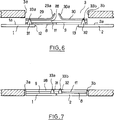
- FIG. 7 show that the door is also called “tacking” and for this purpose comprises in the space 16 located above the opening 3 of the door two fixed guide rails 29, 30 located in the extension of one another and having at their ends adjacent to the middle M of the door two parts 29a, 30a curved towards the outside of the opening 3 of the door.
- Each leaf 1, 2 has at its upper part a tab 31, 32 carrying a finger 33a, 33b engaged in one of the rails 29, 30, to guide the leaf 1, 2 relative to said rail 29, 30.
- the curved parts 29a , 30a rails 29, 30 are used to engage the leaves 1, 2 in the opening 3 of the door in the closed position, as shown in FIG. 7.
- the beam 28 which carries the slides 10, 11, as well as the slides 8, 9 of the leaves 1, 2 are located opposite the face 1a, 2a of the leaves 1, 2 directed to the outside of the door opening 3.
- the beam 28 extends substantially over the entire width of the opening 3 of the door and is free relative to the latter so as to be able to engage in this opening 3, at the same time as the leaves 1, 2 at the end of their closing travel, as shown in Figure 7.
- the electric motor 4 is started in the closing direction.
- This motor 4 rotates the screws 19, 20 in opposite directions, which moves the nuts 6, 7 in opposite directions.
- the nut 6 approaches the motor 4, while the nut 7 moves away therefrom, simultaneously bringing the leaves 1, 2 from the middle M to the opening 3 of the door.
- the main technical advantage of the sliding and swinging door lies in the fact that the entire mechanism 5 for controlling the opening and closing, including its electric motor 4, is housed in the dead space located above the opening 3 of the door without protruding outside the vertical edges 3a and 3b thereof.
- this mechanism 5 and its motor 4 do not clutter the useful space inside the premises or the vehicle.
Landscapes
- Engineering & Computer Science (AREA)
- Mechanical Engineering (AREA)
- Power-Operated Mechanisms For Wings (AREA)
- Lock And Its Accessories (AREA)
- Special Wing (AREA)
- Wing Frames And Configurations (AREA)
- Refrigerator Housings (AREA)
- Specific Sealing Or Ventilating Devices For Doors And Windows (AREA)
Priority Applications (1)
| Application Number | Priority Date | Filing Date | Title |
|---|---|---|---|
| AT91401499T ATE94252T1 (de) | 1990-06-20 | 1991-06-07 | Schiebetuer und ihr antriebsmechanismus. |
Applications Claiming Priority (2)
| Application Number | Priority Date | Filing Date | Title |
|---|---|---|---|
| FR9007709 | 1990-06-20 | ||
| FR9007709A FR2663673B1 (fr) | 1990-06-20 | 1990-06-20 | Porte coulissante et son mecanisme de commande. |
Publications (2)
| Publication Number | Publication Date |
|---|---|
| EP0465281A1 true EP0465281A1 (de) | 1992-01-08 |
| EP0465281B1 EP0465281B1 (de) | 1993-09-08 |
Family
ID=9397818
Family Applications (1)
| Application Number | Title | Priority Date | Filing Date |
|---|---|---|---|
| EP91401499A Expired - Lifetime EP0465281B1 (de) | 1990-06-20 | 1991-06-07 | Schiebetür und ihr Antriebsmechanismus |
Country Status (5)
| Country | Link |
|---|---|
| EP (1) | EP0465281B1 (de) |
| AT (1) | ATE94252T1 (de) |
| DE (2) | DE69100347T2 (de) |
| ES (1) | ES2028748T3 (de) |
| FR (1) | FR2663673B1 (de) |
Cited By (9)
| Publication number | Priority date | Publication date | Assignee | Title |
|---|---|---|---|---|
| US5323876A (en) * | 1992-08-03 | 1994-06-28 | Mcallister Emory C | Elevator door mechanism |
| EP0781892A3 (de) * | 1995-12-28 | 1997-12-10 | Ag Für Türautomation | Automatische Schiebetür mit mindestens einem Flügel |
| EP0837211A3 (de) * | 1996-10-18 | 2000-02-23 | IFE Industrie-Einrichtungen Fertigungs-Aktiengesellschaft | Schiebe- bzw. Schwenkschiebetüre für Fahrzeuge |
| EP1040979A3 (de) * | 1999-03-27 | 2004-12-01 | Gebrüder Bode GmbH & Co.KG | Schwenkschiebetür für Fahrzeuge, insbesondere Fahrzeuge des öffentlichen Personennahverkehrs |
| US8297201B2 (en) | 2007-11-30 | 2012-10-30 | Faiveley Transport | Method to high availability control for railway doors systems, on board system and application to accessories and surroundings of doors |
| CN105484600A (zh) * | 2015-12-31 | 2016-04-13 | 苏州绿尚智能科技有限公司 | 一种推窗器 |
| US10119319B2 (en) | 2013-12-30 | 2018-11-06 | Vapor Europe S.R.L. | Door drive device for a door of a wagon |
| CN110406358A (zh) * | 2018-04-28 | 2019-11-05 | 比亚迪股份有限公司 | 导轨组件和车辆 |
| CN110512989A (zh) * | 2019-09-29 | 2019-11-29 | 金湖县微晶控制系统有限公司 | 塞拉门 |
Families Citing this family (2)
| Publication number | Priority date | Publication date | Assignee | Title |
|---|---|---|---|---|
| FR2768683B1 (fr) | 1997-09-22 | 1999-10-22 | Faiveley Transport | Dispositif motorise de verrouillage de vantail de porte, porte pourvue de ce dispositif et vehicule ferroviaire ainsi equipe |
| CN105275303B (zh) * | 2015-09-16 | 2017-03-29 | 南京康尼机电股份有限公司 | 一种用于轨道车辆塞拉门系统的异步传动装置 |
Citations (4)
| Publication number | Priority date | Publication date | Assignee | Title |
|---|---|---|---|---|
| FR738957A (fr) * | 1932-06-22 | 1933-01-04 | Saunier Anciens Ets | Mécanisme de conjugaison par crémaillères de portes coulissantes |
| CH405981A (de) * | 1963-03-22 | 1966-01-15 | Bator Ag | Türantrieb |
| DE2805411A1 (de) * | 1978-02-09 | 1979-08-16 | Uerdingen Ag Waggonfabrik | Antriebsvorrichtung fuer eine fahrzeugschiebetuer, insbesondere einer haengebahnkabine |
| EP0090951A1 (de) * | 1982-04-02 | 1983-10-12 | Inventio Ag | Zweiflügelschiebetür, insbesondere Aufzugstür |
Family Cites Families (1)
| Publication number | Priority date | Publication date | Assignee | Title |
|---|---|---|---|---|
| DE405981C (de) * | 1923-10-10 | 1924-11-15 | Rolf Sachse | Elektromotorisch angetriebene Sprechmaschine |
-
1990
- 1990-06-20 FR FR9007709A patent/FR2663673B1/fr not_active Expired - Lifetime
-
1991
- 1991-06-07 AT AT91401499T patent/ATE94252T1/de not_active IP Right Cessation
- 1991-06-07 EP EP91401499A patent/EP0465281B1/de not_active Expired - Lifetime
- 1991-06-07 ES ES91401499T patent/ES2028748T3/es not_active Expired - Lifetime
- 1991-06-07 DE DE91401499T patent/DE69100347T2/de not_active Expired - Fee Related
- 1991-06-07 DE DE199191401499T patent/DE465281T1/de active Pending
Patent Citations (4)
| Publication number | Priority date | Publication date | Assignee | Title |
|---|---|---|---|---|
| FR738957A (fr) * | 1932-06-22 | 1933-01-04 | Saunier Anciens Ets | Mécanisme de conjugaison par crémaillères de portes coulissantes |
| CH405981A (de) * | 1963-03-22 | 1966-01-15 | Bator Ag | Türantrieb |
| DE2805411A1 (de) * | 1978-02-09 | 1979-08-16 | Uerdingen Ag Waggonfabrik | Antriebsvorrichtung fuer eine fahrzeugschiebetuer, insbesondere einer haengebahnkabine |
| EP0090951A1 (de) * | 1982-04-02 | 1983-10-12 | Inventio Ag | Zweiflügelschiebetür, insbesondere Aufzugstür |
Cited By (11)
| Publication number | Priority date | Publication date | Assignee | Title |
|---|---|---|---|---|
| US5323876A (en) * | 1992-08-03 | 1994-06-28 | Mcallister Emory C | Elevator door mechanism |
| EP0781892A3 (de) * | 1995-12-28 | 1997-12-10 | Ag Für Türautomation | Automatische Schiebetür mit mindestens einem Flügel |
| EP0837211A3 (de) * | 1996-10-18 | 2000-02-23 | IFE Industrie-Einrichtungen Fertigungs-Aktiengesellschaft | Schiebe- bzw. Schwenkschiebetüre für Fahrzeuge |
| EP1040979A3 (de) * | 1999-03-27 | 2004-12-01 | Gebrüder Bode GmbH & Co.KG | Schwenkschiebetür für Fahrzeuge, insbesondere Fahrzeuge des öffentlichen Personennahverkehrs |
| US8297201B2 (en) | 2007-11-30 | 2012-10-30 | Faiveley Transport | Method to high availability control for railway doors systems, on board system and application to accessories and surroundings of doors |
| US10119319B2 (en) | 2013-12-30 | 2018-11-06 | Vapor Europe S.R.L. | Door drive device for a door of a wagon |
| CN105484600A (zh) * | 2015-12-31 | 2016-04-13 | 苏州绿尚智能科技有限公司 | 一种推窗器 |
| CN110406358A (zh) * | 2018-04-28 | 2019-11-05 | 比亚迪股份有限公司 | 导轨组件和车辆 |
| CN110406358B (zh) * | 2018-04-28 | 2022-09-09 | 比亚迪股份有限公司 | 导轨组件和车辆 |
| CN110512989A (zh) * | 2019-09-29 | 2019-11-29 | 金湖县微晶控制系统有限公司 | 塞拉门 |
| CN110512989B (zh) * | 2019-09-29 | 2024-03-26 | 金湖县微晶控制系统有限公司 | 塞拉门 |
Also Published As
| Publication number | Publication date |
|---|---|
| FR2663673A1 (fr) | 1991-12-27 |
| DE69100347T2 (de) | 1994-01-05 |
| DE69100347D1 (de) | 1993-10-14 |
| ES2028748T3 (es) | 1994-01-01 |
| FR2663673B1 (fr) | 1992-10-23 |
| EP0465281B1 (de) | 1993-09-08 |
| DE465281T1 (de) | 1992-04-30 |
| ATE94252T1 (de) | 1993-09-15 |
| ES2028748T1 (es) | 1992-07-16 |
Similar Documents
| Publication | Publication Date | Title |
|---|---|---|
| EP0465281B1 (de) | Schiebetür und ihr Antriebsmechanismus | |
| FR2666618A1 (fr) | Support articule a friction et fenetre le comportant. | |
| EP1369276A1 (de) | Hintere Haube für Kraftfahrzeug | |
| EP0544582A1 (de) | Führungsvorrichtung einer Schiebeöffnung, zum Beispiel einer Schiebetür, insbesondere für ein Kraftfahrzeug | |
| FR2589938A1 (fr) | Porte coulissante et louvoyante | |
| WO2007096540A1 (fr) | Dispositif de montage articule d'une vitre sur une porte sans cadre de vehicule de type cabriolet ou coupe | |
| FR2712337A1 (fr) | Dispositif de verrouillage à au moins un point de condamnation. | |
| FR2730958A1 (fr) | Toit ouvrant comportant un panneau avant et un panneau arriere independamment manoeuvrable | |
| FR2485608A1 (fr) | Ferrure de fenetre coulissante, porte coulissante ou analogue | |
| EP0290355B1 (de) | Falttürenantriebsvorrichtung für Fahrkörbe von Aufzügen | |
| FR2599780A1 (fr) | Dispositif d'actionnement electromecanique pour porte a deplacement coulissant | |
| FR2818591A1 (fr) | Systeme d'ouvrants, notamment pour vehicule automobile | |
| FR2518156A1 (fr) | Agencement de porte | |
| FR2752865A1 (fr) | Serrure pour un battant, tel qu'une porte, de vehicule automobile | |
| EP0401081A1 (de) | Führungsvorrichtung für eine Schiebetür und Fahrzeug mit einer solchen Vorrichtung | |
| EP0788960A1 (de) | System zum Verschliessen einer Öffnung in einem Wagenkasten | |
| FR2631369A1 (fr) | Serrure a bascule, en particulier pour bagage | |
| EP0028973A1 (de) | Vorrichtung zum Bewegen eines Kipptores und so ausgerüstetes Tor | |
| EP0034965A1 (de) | Antriebsvorrichtung für eine Schiebewand | |
| FR2891497A1 (fr) | Porte laterale coulissante equipee de moyens de guidage. | |
| FR2701987A1 (fr) | Dispositif de fermeture de porte. | |
| EP0000320A1 (de) | Faltschiebedach | |
| FR2734208A1 (fr) | Agencement d'une porte laterale sur un vehicule automobile | |
| FR2587657A1 (fr) | Dispositif de toit ouvrant pour pavillon de vehicule automobile | |
| FR2552481A1 (fr) | Mecanisme de motorisation pour portes basculantes et portes sectionnelles |
Legal Events
| Date | Code | Title | Description |
|---|---|---|---|
| PUAI | Public reference made under article 153(3) epc to a published international application that has entered the european phase |
Free format text: ORIGINAL CODE: 0009012 |
|
| 17P | Request for examination filed |
Effective date: 19910614 |
|
| AK | Designated contracting states |
Kind code of ref document: A1 Designated state(s): AT BE DE ES GB IT NL |
|
| ITCL | It: translation for ep claims filed |
Representative=s name: BARZANO' E ZANARDO ROMA S.P.A. |
|
| GBC | Gb: translation of claims filed (gb section 78(7)/1977) | ||
| TCAT | At: translation of patent claims filed | ||
| 17Q | First examination report despatched |
Effective date: 19920225 |
|
| DET | De: translation of patent claims | ||
| ITF | It: translation for a ep patent filed | ||
| GRAA | (expected) grant |
Free format text: ORIGINAL CODE: 0009210 |
|
| AK | Designated contracting states |
Kind code of ref document: B1 Designated state(s): AT BE DE ES GB IT NL |
|
| REF | Corresponds to: |
Ref document number: 94252 Country of ref document: AT Date of ref document: 19930915 Kind code of ref document: T |
|
| GBT | Gb: translation of ep patent filed (gb section 77(6)(a)/1977) |
Effective date: 19930903 |
|
| REF | Corresponds to: |
Ref document number: 69100347 Country of ref document: DE Date of ref document: 19931014 |
|
| REG | Reference to a national code |
Ref country code: ES Ref legal event code: FG2A Ref document number: 2028748 Country of ref document: ES Kind code of ref document: T3 |
|
| PLBE | No opposition filed within time limit |
Free format text: ORIGINAL CODE: 0009261 |
|
| STAA | Information on the status of an ep patent application or granted ep patent |
Free format text: STATUS: NO OPPOSITION FILED WITHIN TIME LIMIT |
|
| 26N | No opposition filed | ||
| PGFP | Annual fee paid to national office [announced via postgrant information from national office to epo] |
Ref country code: GB Payment date: 20010529 Year of fee payment: 11 |
|
| PGFP | Annual fee paid to national office [announced via postgrant information from national office to epo] |
Ref country code: AT Payment date: 20010620 Year of fee payment: 11 |
|
| PGFP | Annual fee paid to national office [announced via postgrant information from national office to epo] |
Ref country code: ES Payment date: 20010622 Year of fee payment: 11 |
|
| PGFP | Annual fee paid to national office [announced via postgrant information from national office to epo] |
Ref country code: NL Payment date: 20010630 Year of fee payment: 11 |
|
| PGFP | Annual fee paid to national office [announced via postgrant information from national office to epo] |
Ref country code: BE Payment date: 20010727 Year of fee payment: 11 |
|
| PGFP | Annual fee paid to national office [announced via postgrant information from national office to epo] |
Ref country code: DE Payment date: 20010830 Year of fee payment: 11 |
|
| REG | Reference to a national code |
Ref country code: GB Ref legal event code: IF02 |
|
| PG25 | Lapsed in a contracting state [announced via postgrant information from national office to epo] |
Ref country code: GB Free format text: LAPSE BECAUSE OF NON-PAYMENT OF DUE FEES Effective date: 20020607 Ref country code: AT Free format text: LAPSE BECAUSE OF NON-PAYMENT OF DUE FEES Effective date: 20020607 |
|
| PG25 | Lapsed in a contracting state [announced via postgrant information from national office to epo] |
Ref country code: ES Free format text: LAPSE BECAUSE OF NON-PAYMENT OF DUE FEES Effective date: 20020608 |
|
| PG25 | Lapsed in a contracting state [announced via postgrant information from national office to epo] |
Ref country code: BE Free format text: LAPSE BECAUSE OF NON-PAYMENT OF DUE FEES Effective date: 20020630 |
|
| BERE | Be: lapsed |
Owner name: *FAIVELEY TRANSPORT Effective date: 20020630 |
|
| PG25 | Lapsed in a contracting state [announced via postgrant information from national office to epo] |
Ref country code: NL Free format text: LAPSE BECAUSE OF NON-PAYMENT OF DUE FEES Effective date: 20030101 Ref country code: DE Free format text: LAPSE BECAUSE OF NON-PAYMENT OF DUE FEES Effective date: 20030101 |
|
| GBPC | Gb: european patent ceased through non-payment of renewal fee |
Effective date: 20020607 |
|
| NLV4 | Nl: lapsed or anulled due to non-payment of the annual fee |
Effective date: 20030101 |
|
| REG | Reference to a national code |
Ref country code: ES Ref legal event code: FD2A Effective date: 20030711 |
|
| PG25 | Lapsed in a contracting state [announced via postgrant information from national office to epo] |
Ref country code: IT Free format text: LAPSE BECAUSE OF NON-PAYMENT OF DUE FEES;WARNING: LAPSES OF ITALIAN PATENTS WITH EFFECTIVE DATE BEFORE 2007 MAY HAVE OCCURRED AT ANY TIME BEFORE 2007. THE CORRECT EFFECTIVE DATE MAY BE DIFFERENT FROM THE ONE RECORDED. Effective date: 20050607 |