EP0465282B1 - Kugeldrehantrieb - Google Patents
Kugeldrehantrieb Download PDFInfo
- Publication number
- EP0465282B1 EP0465282B1 EP91401522A EP91401522A EP0465282B1 EP 0465282 B1 EP0465282 B1 EP 0465282B1 EP 91401522 A EP91401522 A EP 91401522A EP 91401522 A EP91401522 A EP 91401522A EP 0465282 B1 EP0465282 B1 EP 0465282B1
- Authority
- EP
- European Patent Office
- Prior art keywords
- balls
- piston
- ramps
- helical
- ball
- Prior art date
- Legal status (The legal status is an assumption and is not a legal conclusion. Google has not performed a legal analysis and makes no representation as to the accuracy of the status listed.)
- Expired - Lifetime
Links
- 238000006073 displacement reaction Methods 0.000 claims description 6
- 230000002093 peripheral effect Effects 0.000 claims 2
- 230000003134 recirculating effect Effects 0.000 description 2
- 230000001133 acceleration Effects 0.000 description 1
- 238000001514 detection method Methods 0.000 description 1
- 230000000694 effects Effects 0.000 description 1
Images



Classifications
-
- F—MECHANICAL ENGINEERING; LIGHTING; HEATING; WEAPONS; BLASTING
- F15—FLUID-PRESSURE ACTUATORS; HYDRAULICS OR PNEUMATICS IN GENERAL
- F15B—SYSTEMS ACTING BY MEANS OF FLUIDS IN GENERAL; FLUID-PRESSURE ACTUATORS, e.g. SERVOMOTORS; DETAILS OF FLUID-PRESSURE SYSTEMS, NOT OTHERWISE PROVIDED FOR
- F15B15/00—Fluid-actuated devices for displacing a member from one position to another; Gearing associated therewith
- F15B15/02—Mechanical layout characterised by the means for converting the movement of the fluid-actuated element into movement of the finally-operated member
- F15B15/06—Mechanical layout characterised by the means for converting the movement of the fluid-actuated element into movement of the finally-operated member for mechanically converting rectilinear movement into non- rectilinear movement
- F15B15/068—Mechanical layout characterised by the means for converting the movement of the fluid-actuated element into movement of the finally-operated member for mechanically converting rectilinear movement into non- rectilinear movement the motor being of the helical type
-
- B—PERFORMING OPERATIONS; TRANSPORTING
- B64—AIRCRAFT; AVIATION; COSMONAUTICS
- B64C—AEROPLANES; HELICOPTERS
- B64C13/00—Control systems or transmitting systems for actuating flying-control surfaces, lift-increasing flaps, air brakes, or spoilers
- B64C13/24—Transmitting means
- B64C13/26—Transmitting means without power amplification or where power amplification is irrelevant
- B64C13/36—Transmitting means without power amplification or where power amplification is irrelevant fluid
-
- F—MECHANICAL ENGINEERING; LIGHTING; HEATING; WEAPONS; BLASTING
- F16—ENGINEERING ELEMENTS AND UNITS; GENERAL MEASURES FOR PRODUCING AND MAINTAINING EFFECTIVE FUNCTIONING OF MACHINES OR INSTALLATIONS; THERMAL INSULATION IN GENERAL
- F16H—GEARING
- F16H25/00—Gearings comprising primarily only cams, cam-followers and screw-and-nut mechanisms
- F16H25/18—Gearings comprising primarily only cams, cam-followers and screw-and-nut mechanisms for conveying or interconverting oscillating or reciprocating motions
- F16H25/20—Screw mechanisms
- F16H25/22—Screw mechanisms with balls, rollers, or similar members between the co-operating parts; Elements essential to the use of such members
- F16H25/2204—Screw mechanisms with balls, rollers, or similar members between the co-operating parts; Elements essential to the use of such members with balls
- F16H25/2233—Screw mechanisms with balls, rollers, or similar members between the co-operating parts; Elements essential to the use of such members with balls with cages or means to hold the balls in position
-
- Y—GENERAL TAGGING OF NEW TECHNOLOGICAL DEVELOPMENTS; GENERAL TAGGING OF CROSS-SECTIONAL TECHNOLOGIES SPANNING OVER SEVERAL SECTIONS OF THE IPC; TECHNICAL SUBJECTS COVERED BY FORMER USPC CROSS-REFERENCE ART COLLECTIONS [XRACs] AND DIGESTS
- Y10—TECHNICAL SUBJECTS COVERED BY FORMER USPC
- Y10T—TECHNICAL SUBJECTS COVERED BY FORMER US CLASSIFICATION
- Y10T74/00—Machine element or mechanism
- Y10T74/18—Mechanical movements
- Y10T74/18888—Reciprocating to or from oscillating
- Y10T74/18984—Inclined ramp
-
- Y—GENERAL TAGGING OF NEW TECHNOLOGICAL DEVELOPMENTS; GENERAL TAGGING OF CROSS-SECTIONAL TECHNOLOGIES SPANNING OVER SEVERAL SECTIONS OF THE IPC; TECHNICAL SUBJECTS COVERED BY FORMER USPC CROSS-REFERENCE ART COLLECTIONS [XRACs] AND DIGESTS
- Y10—TECHNICAL SUBJECTS COVERED BY FORMER USPC
- Y10T—TECHNICAL SUBJECTS COVERED BY FORMER US CLASSIFICATION
- Y10T74/00—Machine element or mechanism
- Y10T74/19—Gearing
- Y10T74/19642—Directly cooperating gears
- Y10T74/19698—Spiral
- Y10T74/19702—Screw and nut
- Y10T74/19744—Rolling element engaging thread
- Y10T74/19781—Non-recirculating rolling elements
- Y10T74/19786—Captured sphere
Definitions
- the invention relates generally to control devices for coaxial output members pivoting with respect to each other such as aircraft control surfaces with respect to the wing, and more particularly rotary ball jacks .
- the first family poses problems of rigidity, mainly if one wants to have a significant torque in the smallest possible thickness.
- the second family poses leakage (and therefore yield) problems.
- the third family that of rotary ball cylinders, has great advantages in terms of performance, rigidity and service life.
- recirculating ball cylinders have been designed, such as that described in document US-A-4 134 329 in the name of the applicant, the teaching of which is incorporated in the present application, or the document US-A -4 738 415.
- a jack is generally satisfactory and reference may also be made to the article "Rotary Servohinge Actuator” by George Miller Jr. and Mark Williams, published in SAE Technical Paper Series in 1989 (ISSN 0148-7191) illustrating a more elaborate version of a rotary recirculating cylinder.
- the ball recirculation circuit has two relatively undesirable consequences: an increase in the number of balls and an increase in the width of the jack, resulting in an increase in weight.
- the object of the invention is to obtain a rotary cylinder with non-recycled balls free of the drawbacks mentioned, and allowing a significant reduction in size and weight.
- the invention provides a first embodiment of a rotary ball jack, as defined in appended claim 1.
- the first balls and second balls are held respectively in first and second ball cages interposed between the piston and the body, as known from document FR-A-833 386. This ensures that the balls are not likely to accumulate .
- the first and second balls, as well as the first and second cages, are preferably arranged substantially on the same virtual cylinder, in the extension of each other, so as to avoid any excess thickness.
- the first and second cages are slaved to the movement of the piston so that the position of the balls is perfectly defined at all times, even in the event of numerous vibrations of the device incorporating the jack.
- the first and second cages are formed by the first and second parts of a single cage.
- This comprises a cylindrical envelope which cooperates by means of a lug device and helical ramp with one of the two parts of the body, in principle the mobile part.
- the envelope has receiving holes for the balls of the helical and rectilinear ramps.
- the holes provided in one of the two parts preferably the part assigned to the balls of the straight ramps, offer axial guidance of the balls but no circumferential guidance so as to allow different angular displacement of the balls in one and the other parties.
- the holes in the part assigned to the straight ramps are circumferentially elongated.
- the jack 1 comprises a fixed hollow cylindrical body 2 comprising on its outer surface a part 3 for fixing to the fixed part of a wing, not shown, by suitable fasteners.
- a pivoting hollow cylindrical body 4 is arranged coaxially in the extension of the fixed body 2 and is connected to a pivoting aerodynamic surface, not shown, by means of a fixing part 5 and suitable fixing means.
- the pivoting body 4 is mounted in rotation relative to the fixed body 2, and is locked in translation relative to the latter.
- a piston 6 is housed inside the bodies 2 and 4 of the cylinder 1 and comprises a head 7 for interfacing with a hydraulic control cylinder (not shown) intended to impart an axial thrust to it.
- the fixed body 2 has inside helical ramps 8 of hardness and shape suitable for the passage of balls 9 held on the other side by corresponding helical ramps 10 formed on the surface facing the piston 6.
- the pivoting body 4 comprises rectilinear tracks 11 equidistant, of hardness and shape suitable for the passage of balls 12, held on the other side by corresponding rectilinear tracks 13 formed on the facing surface of the piston 6.
- the piston 6 When the piston 6 receives an axial thrust, it moves in translation relative to the bodies 2 and 4 of the jack, and simultaneously in rotation relative to the fixed body 2 under the screw-nut effect resulting from the cooperation of the helical ramps 8, 10.
- the body 4 is integral in rotation with the piston 6 (thanks to the rectilinear keying tracks) but integral in translation with the fixed body 2, the induced helical movement of the piston 6 drives the pivoting body 4 in rotation.
- the balls are, in the solution of the prior art, arranged contiguously in a closed circuit comprising recirculation paths 14 and 15 that the present invention has precisely to eliminate, because they lead in particular to an increase in the overall size of the jack.
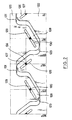
- the invention provides for introducing a ball cage for the balls of the helical and straight tracks, as will be seen. explain with reference to Figures 1 and 2.
- FIG. 1 shows the jack 101 consisting of the fixed 102 and pivoting 104 body, mounted in free rotation and blocked translation by means of a ball bearing 120 interposed between a flange 121 secured to the body 102 and the external surface of the body pivoting 104 partially covered by said cylindrical flange 121.
- the piston 106 is capable of receiving the control thrust on its face 107.
- the piston 106 comprises: on the one hand, helical ramps 110 (for example 18 ramps with a pitch of 360 mm) which cooperate by means of balls 109 with the helical ramps 108 of the body 102; and on the other hand, rectilinear tracks or ramps 113 (for example 24 circumferentially distributed tracks) cooperating by means of the balls 112 with the rectilinear tracks 111 of the pivoting body 104.
- the balls 109 of the helical ramps are held integral by a ball cage 122 constituted by a thin-walled cylinder pierced with receiving holes arranged in helices in which the balls 109 are engaged. It is clear that the presence of the ball cage 122 increases very little the total diameter of the cylinder.
- the cylinder constituting the cage 122 ends, on the side of the piston 106 directed towards the rectilinear tracks, by a crenellated edge of which the two crenels 123 separate two teeth 124; their role will be explained later.
- the balls 112 of the rectilinear tracks are held in the holes arranged in lines of a second ball cage 125, constituted like the first (if not the arrangement of the holes, adapted to the configuration of the tracks) . It is also provided, on the side facing the helical ramps, with a crenellated edge. The crenellated edges of the two cages interpenetrate.
- the holes in the cages are slightly larger in dimension than the balls they hold so as to allow them to roll.
- the movement of the cages is controlled by the movement of the movable members to ensure the rigorous positioning of the balls.
- the first cage 122 must follow a helical movement whose speed of advance and speed of rotation are equal to half of the speeds of advance and rotation of the movable member relative to the fixed member.
- the two teeth 124 of the cage 122 comprise two helical ramps 126 (produced in the form of lights) which cooperate with two lugs 127 secured to the pivoting body 104.
- the inclination of the ramps 126 is calculated so that the rotary movement of the pin 127 moving in the light 126 induces the speed of advance required for the cage.
- the second cage 125 must move, along a path that is also helical, at a speed of advance half the translation speed of the piston 106 relative to the body 104 but at a speed of rotation equal to that of the body 104.
- the teeth 128 of the crenellated edge of the cage 125 comprise two helical slots 129 which cooperate with two lugs 130 secured to the fixed body 102.
- the inclination of the slots 129 is such that, when the body 104 pivots and the cage 125 is driven, the fixed lugs 130 push on the lights so as to adjust the cage 125 at the desired speed.
- the teeth 124 of the first cage 122 penetrate into the slots 131 of the second (and vice versa), at the level of the flange 121, leaving a sufficient circumferential spacing between the two cages to allow relative rotation of one with respect to the other, which is necessary taking into account the angular speed of the cage 125 which is double that of the cage 122.
- the circumferential spacing is sufficient to allow the realization of the limited rotational movement of the body 104 relative to the body 102.
- Figures 4 and 5 are shown the elements of a second embodiment of the cylinder in which the two cages are combined into one.
- the single cylindrical cage 140 (FIG. 5) combines two parts 122 ′ and 125 ′ intended to guide the balls 109 ′ of the helical tracks 108′-110 ′ and the balls 112 ′ of the straight tracks 111′-113 ′ respectively. .
- the holes 141 for receiving the balls are substantially circular (apart from the curvature of the cylinder constituting the cage) and slightly larger than the balls 109 ′. As in the first embodiment, they are arranged in propellers corresponding to the position of the balls 109 ′ in the helical ramps.
- the part 125 ′ has holes 142 elongated in the direction of the circumference of the cylinder, while their width corresponds substantially to that of the balls 112 ′.
- This elongation of the holes allows the balls 112 ′ to have, during their helical displacement, a different angular speed (double) than that of the single cage 140 whose angular speed is equal to that of the balls 109 ′.
- the movement of the single cage 140 is controlled by at least one helical ramp 126 ′ produced in the form of light, which cooperates with at least one lug 127 ′ secured to the pivoting body 104 ′.
- This embodiment has the advantage compared to the previous one of not requiring the relatively delicate cuts of the two separate cages at the level of their nesting.
Landscapes
- Engineering & Computer Science (AREA)
- General Engineering & Computer Science (AREA)
- Mechanical Engineering (AREA)
- Automation & Control Theory (AREA)
- Aviation & Aerospace Engineering (AREA)
- Physics & Mathematics (AREA)
- Fluid Mechanics (AREA)
- Transmission Devices (AREA)
- Actuator (AREA)
- Pivots And Pivotal Connections (AREA)
Claims (4)
- Kugeldrehantrieb mit einem Kolben (106), der in einem Hohlzylinderkörper untergebracht ist, der aus zwei Teilen (102,104) besteht, die zueinander translationsfest und frei drehbar sind, wobei der Kolben (106) auf seiner Umfangsfläche gegenüber dem ersten Teil (102) schraubenförmige Rampen (110) aufweist, die über erste Kugeln (109) mit schraubenförmgen Rampen (108) zusammenwirken, die auf der Innenseite des ersten Teils (102) ausgeformt sind, und gegenüber dem zweiten Teil (104) geradlinige Rampen (113) aufweist, die über zweite Kugeln (112) mit geradlinigen Rampen (111) zusammenwirken, die auf der Innenseite des zweiten Teils (104) ausgeformt sind, wodurch bewirkt wird, daß ein auf den Kolben (106) ausgeübter Schub, da einer der Teile (102,104) ortsfest ist, eine Drehung des anderen (104,102) der Teile mit sich bringt, dadurch gekennzeichnet, daß die ersten (109) und die zweiten (112) Kugeln jeweils in einem ersten (122) und zweiten (125) Kugelkäfig gehalten sind, die zwischen dem Kolben (106) und dem Körper (102,104) eingebracht sind und an die Drehung des Kolbens (106) gebunden sind, und daß die Käfige (122,125) unterschiedlich sind und jeder einen gezackten Zylinderkörper aufweist, dessen Zähne (124,128) jeweils in die Zinnen (131,123) des gezackten Randes des anderen Käfigs (122,125) eindringen, wobei jeder Zahn (124,128) ein schraubenförmiges Langloch (126,129) aufweist, das mit einem Vorsprung (127,130) zusammenwirkt, der mit dem entsprechenden Teil (102,104) des Antriebskörpers fest verbunden ist.
- Kugeldrehantrieb mit einem Kolben (106'), der in einem Hohlzylinderkörper untergebracht ist, der aus zwei Teilen (102',104') besteht, die zueinander translationsfest und frei drehbar sind, wobei der Kolben (106') auf seiner Umfangsfläche gegenüber dem ersten Teil (102') schraubenförmige Rampen (110') aufweist, die über erste Kugeln (109') mit schraubenförmigen Rampen (108') zusammenwirken, die auf der Innenseite des ersten Teils (102') ausgeformt sind, und gegenüber dem zweiten Teil (104') geradlinige Rampen (113') aufweist, die über zweite Kugeln (109') mit schraubenförmigen Rampen (108') zusammenwirken, die auf der Innenseite des ersten Teils (102') ausgeformt sind, und gegenüber dem zweiten Teil (104') geradlinige Rampen (113') aufweist, die über zweite Kugeln (112') mit geradlinigen Rampen (111') zusammenwirken, die auf der Innenseite des zweiten Teils (104') ausgeformt sind, wodurch bewirkt wird, daß ein auf den Kolben (106') ausgeübter Schub, da einer der Teile (102',104') ortsfest ist, eine Drehung des anderen (104', 102') der Teile mit sich bringt, dadurch gekennzeichnet, daß die ersten Kugeln (109') und zweiten Kugeln (112') in einem ersten (122') und zweiten (125') Kugelkäfig gehalten sind, die zwischen dem Kolben (106') und dem Körper (102',104') angebracht sind und an die Drehung des Kolbens gebunden sind, und daß der erste und zweite Käfig gebildet ist durch einen ersten und zweiten Teil (122', 125') eines einteiligen Käfigs (140).
- Kugeldrehantrieb nach Anspruch 2, dadurch gekennzeichnet, daß der einteilige Käfig (140) ein zylindrisches Gehäuse aufweist, welches über eine Nockenvorrichtung (127') und die schraubenförmige Rampe (126') mit einem (104') der beiden Teile des Körpers zusammenwirkt.
- Kugeldrehantrieb nach Anspruch 2 oder 3, dadurch gekennzeichnet, daß die Kugelaufnahmelöcher (141, 142) des einen der beiden Teile (122',125') des Käfigs (140) in Umfangsrichtung verlängert sind, um eine unterschiedliche Winkelversetzung der in dem einen und anderen Teil aufgenommenen Kugeln zu ermöglichen.
Applications Claiming Priority (2)
| Application Number | Priority Date | Filing Date | Title |
|---|---|---|---|
| FR909008215A FR2663994B1 (fr) | 1990-06-29 | 1990-06-29 | Verin rotatif a billes. |
| FR9008215 | 1990-06-29 |
Publications (2)
| Publication Number | Publication Date |
|---|---|
| EP0465282A1 EP0465282A1 (de) | 1992-01-08 |
| EP0465282B1 true EP0465282B1 (de) | 1994-08-24 |
Family
ID=9398149
Family Applications (1)
| Application Number | Title | Priority Date | Filing Date |
|---|---|---|---|
| EP91401522A Expired - Lifetime EP0465282B1 (de) | 1990-06-29 | 1991-06-10 | Kugeldrehantrieb |
Country Status (5)
| Country | Link |
|---|---|
| US (1) | US5178030A (de) |
| EP (1) | EP0465282B1 (de) |
| JP (1) | JPH086791B2 (de) |
| DE (1) | DE69103588T2 (de) |
| FR (1) | FR2663994B1 (de) |
Families Citing this family (20)
| Publication number | Priority date | Publication date | Assignee | Title |
|---|---|---|---|---|
| US20070091230A1 (en) * | 1993-12-21 | 2007-04-26 | 3M Innovative Properties Company | Display incorporating reflective polarizer |
| US6672540B1 (en) | 2002-12-03 | 2004-01-06 | Rockwell Collins, Inc. | Actuator for aircraft stabilizers with a failure responsive lock control mechanism |
| ITRM20030169A1 (it) * | 2003-04-11 | 2004-10-12 | Umbra Cuscinetti Spa | Attuatore a ricircolo di sfere per superfici di governo di aermobili. |
| DE202004016324U1 (de) * | 2004-10-20 | 2006-03-02 | Trumpf Werkzeugmaschinen Gmbh + Co. Kg | Spindelantrieb mit Wälzkörperkäfig und Käfigführung |
| EP1896728A4 (de) * | 2005-06-15 | 2009-06-03 | Razorback Vehicles Corp Ltd | Druckluft- oder hydraulikzylinder |
| WO2008050543A1 (fr) * | 2006-09-29 | 2008-05-02 | Thk Co., Ltd. | Dispositif à vis de corps de roulement |
| US20090193915A1 (en) * | 2008-02-01 | 2009-08-06 | Feng-Ho Wang | Separable ball screw |
| JP5120040B2 (ja) * | 2008-04-14 | 2013-01-16 | 株式会社ジェイテクト | ボールねじ装置およびそれを用いた電動パワーステアリング装置 |
| KR100929529B1 (ko) * | 2009-06-03 | 2009-12-03 | 정봉식 | 로터리 엑츄에이터에 내장되는 볼 타입의 회전체 및 그 제조방법 |
| CN103291450B (zh) * | 2012-02-24 | 2017-09-26 | 刘素华 | 一种发动机活塞滚动摩擦或悬浮摩擦的方法及其实施该方法的防磨损活塞发动机 |
| CN103352697B (zh) * | 2012-02-24 | 2020-11-20 | 刘素华 | 导向多点支撑往复冲击器的方法及实施该方法的导向多点支撑往复冲击器装置 |
| CN103498869B (zh) * | 2012-05-12 | 2020-05-01 | 刘素华 | 带架滚动摩擦往复运动方法及带架直线往复滚动导向装置 |
| CN103388620B (zh) * | 2012-05-12 | 2019-07-16 | 刘素华 | 往复运动滚动摩擦且滚动导向的方法及直线往复滚动摩擦且滚动导向装置 |
| CN103912483A (zh) * | 2012-12-26 | 2014-07-09 | 刘素华 | 一种抽油机活塞滚动摩擦的方法及实施该方法的活塞滚动摩擦抽油机 |
| US10633080B2 (en) * | 2016-07-22 | 2020-04-28 | The Boeing Company | Electronically controlled rotary actuator for an aircraft control surface |
| US12157199B2 (en) * | 2019-02-22 | 2024-12-03 | Borgwarner Inc. | Centerless grinding through the application of a helical twist to axial grooves |
| US11549526B2 (en) * | 2021-03-18 | 2023-01-10 | United States Of America As Represented By The Secretary Of The Air Force | Linear and rotary actuators |
| US11820489B2 (en) | 2021-10-01 | 2023-11-21 | The Boeing Company | Ball screw rotary actuator with ball cage |
| US20240067255A1 (en) * | 2022-08-31 | 2024-02-29 | Steering Solutions Ip Holding Corporation | Steer-by-wire road wheel actuator multi-groove ball screw anti-rotation mechanism |
| US20240140523A1 (en) * | 2022-08-31 | 2024-05-02 | Steering Solutions Ip Holding Corporation | Steer-by-wire road wheel actuator multi-groove ball screw anti-rotation mechanism |
Family Cites Families (9)
| Publication number | Priority date | Publication date | Assignee | Title |
|---|---|---|---|---|
| GB510798A (en) * | 1937-02-09 | 1939-08-08 | Eclipse Aviat Corp | Improvements in or relating to screw and nut gearing |
| US2739491A (en) * | 1952-09-13 | 1956-03-27 | Eaton Mfg Co | Mechanical movement device |
| US2690683A (en) * | 1953-02-26 | 1954-10-05 | Roller Gear Company Inc | Ball bearing screw |
| US2711655A (en) * | 1954-05-13 | 1955-06-28 | Roller Gear Company Inc | Ball bearing screw device |
| SU734429A1 (ru) * | 1975-10-01 | 1980-05-17 | За витель | Устройство дл преобразовани возвратно-поступательного движени поршней в направленное непрерывное вращение выходного вала |
| US4691582A (en) * | 1984-01-30 | 1987-09-08 | Weyer Paul P | Thin profile rotary actuator with backlash elimination |
| US4643401A (en) * | 1985-08-28 | 1987-02-17 | Mg Industries | Apparatus for cooling a vacuum furnace |
| US4738415A (en) * | 1986-10-17 | 1988-04-19 | Weyer Paul P | Hinge line flight actuator |
| US4887479A (en) * | 1988-07-26 | 1989-12-19 | Sundstrand Corporation | Ball cage for helical ballspline |
-
1990
- 1990-06-29 FR FR909008215A patent/FR2663994B1/fr not_active Expired - Fee Related
-
1991
- 1991-06-10 EP EP91401522A patent/EP0465282B1/de not_active Expired - Lifetime
- 1991-06-10 DE DE69103588T patent/DE69103588T2/de not_active Expired - Fee Related
- 1991-06-20 US US07/718,379 patent/US5178030A/en not_active Expired - Lifetime
- 1991-06-28 JP JP3159074A patent/JPH086791B2/ja not_active Expired - Fee Related
Also Published As
| Publication number | Publication date |
|---|---|
| DE69103588T2 (de) | 1995-04-13 |
| FR2663994A1 (fr) | 1992-01-03 |
| EP0465282A1 (de) | 1992-01-08 |
| FR2663994B1 (fr) | 1994-06-10 |
| JPH086791B2 (ja) | 1996-01-29 |
| JPH04231705A (ja) | 1992-08-20 |
| DE69103588D1 (de) | 1994-09-29 |
| US5178030A (en) | 1993-01-12 |
Similar Documents
| Publication | Publication Date | Title |
|---|---|---|
| EP0465282A1 (de) | Kugeldrehantrieb | |
| EP1550837B1 (de) | Vorrichtung zur Entfaltung und Steuerung der Steuerflächen eines Projektils | |
| BE1017685A3 (fr) | Chaine porteuse de cables pour volet mobile de bord d'attaque d'une aile d'aeronef. | |
| CA2169874C (fr) | Inverseur de poussee a volets aval pour turboreacteur | |
| FR2957329A1 (fr) | Mecanisme de calage variable de pales pour systeme d'helices contrarotatives et systeme d'helices contrarotatives comportant au moins un tel mecanisme | |
| EP0460988A1 (de) | Steuervorrichtung mit Nockenwelle und Kraftübertragungsmittel mit Rolle | |
| EP0870105B1 (de) | Ausfahrbare raketentriebwerkdüse | |
| FR2977862A1 (fr) | Dispositif de commande de l'orientation des pales de soufflante d'un turbopropulseur | |
| FR2999154A1 (fr) | Centreur d'assemblage pour nacelle de turboreacteur | |
| EP4267838B1 (de) | Lufteinlass für eine flugzeugantriebseinheit mit einem element zur bewegung eines beweglichen vorgelagerten teils und verfahren zur verwendung eines solchen lufteinlasses | |
| EP3956224B1 (de) | Turbofantriebwerk umfassend einer gondel mit einem lufteinlass um eine schubumkehrphase zu bessern | |
| FR2495237A3 (fr) | Ensemble de pompage monobloc pour pompes centrifuges | |
| FR2600618A1 (fr) | Aile a deploiement multiple, et son application a un engin volant | |
| EP3696397A1 (de) | Gondel eines turboreaktors, die eine blockiertür und ein system zum einsatz einer solchen blockiertür umfasst | |
| WO2023012425A1 (fr) | Module de soufflante a pales a calage variable | |
| BE1024234B1 (fr) | Aile d’aeronef comprenant un volet mobile de bord d’attaque entraine par un moteur electrique lineaire | |
| FR3126018A1 (fr) | Systeme de changement de pas des pales d’une soufflante d’un ensemble propulsif | |
| WO2017144807A1 (fr) | Moyeu d'hélice à pales à calage variable avec variation radiale et axiale de dimensionnement | |
| FR3046404A1 (fr) | Dispositif de commande de l'orientation des pales de soufflante d'un turbopropulseur | |
| WO2014016512A1 (fr) | Dispositif d'entrainement de volets notamment pour tuyère adaptative | |
| FR3046405A1 (fr) | Dispositif de commande de l'orientation des pales de soufflante d'un turbopropulseur | |
| FR3139795A1 (fr) | Module de soufflante a pales a calage variable | |
| FR2885699A1 (fr) | Dispositif d'accouplement en rotation d'une roue d'avion et d'un tachymetre. | |
| CH684549A5 (fr) | Aile galbée déployable pour engin volant. | |
| FR3098791A1 (fr) | Dispositif de précharge pour roulement à billes de moteur électrique et moteur électrique équipé d’un tel dispositif de précharge |
Legal Events
| Date | Code | Title | Description |
|---|---|---|---|
| PUAI | Public reference made under article 153(3) epc to a published international application that has entered the european phase |
Free format text: ORIGINAL CODE: 0009012 |
|
| AK | Designated contracting states |
Kind code of ref document: A1 Designated state(s): DE FR GB IT |
|
| 17P | Request for examination filed |
Effective date: 19920204 |
|
| 17Q | First examination report despatched |
Effective date: 19930324 |
|
| GRAA | (expected) grant |
Free format text: ORIGINAL CODE: 0009210 |
|
| AK | Designated contracting states |
Kind code of ref document: B1 Designated state(s): DE FR GB IT |
|
| GBT | Gb: translation of ep patent filed (gb section 77(6)(a)/1977) |
Effective date: 19940826 |
|
| REF | Corresponds to: |
Ref document number: 69103588 Country of ref document: DE Date of ref document: 19940929 |
|
| ITF | It: translation for a ep patent filed | ||
| PLBE | No opposition filed within time limit |
Free format text: ORIGINAL CODE: 0009261 |
|
| STAA | Information on the status of an ep patent application or granted ep patent |
Free format text: STATUS: NO OPPOSITION FILED WITHIN TIME LIMIT |
|
| 26N | No opposition filed | ||
| REG | Reference to a national code |
Ref country code: GB Ref legal event code: IF02 |
|
| PGFP | Annual fee paid to national office [announced via postgrant information from national office to epo] |
Ref country code: GB Payment date: 20040513 Year of fee payment: 14 |
|
| PGFP | Annual fee paid to national office [announced via postgrant information from national office to epo] |
Ref country code: DE Payment date: 20040820 Year of fee payment: 14 |
|
| PG25 | Lapsed in a contracting state [announced via postgrant information from national office to epo] |
Ref country code: IT Free format text: LAPSE BECAUSE OF NON-PAYMENT OF DUE FEES;WARNING: LAPSES OF ITALIAN PATENTS WITH EFFECTIVE DATE BEFORE 2007 MAY HAVE OCCURRED AT ANY TIME BEFORE 2007. THE CORRECT EFFECTIVE DATE MAY BE DIFFERENT FROM THE ONE RECORDED. Effective date: 20050610 Ref country code: GB Free format text: LAPSE BECAUSE OF NON-PAYMENT OF DUE FEES Effective date: 20050610 |
|
| PG25 | Lapsed in a contracting state [announced via postgrant information from national office to epo] |
Ref country code: DE Free format text: LAPSE BECAUSE OF NON-PAYMENT OF DUE FEES Effective date: 20060103 |
|
| GBPC | Gb: european patent ceased through non-payment of renewal fee |
Effective date: 20050610 |
|
| PGFP | Annual fee paid to national office [announced via postgrant information from national office to epo] |
Ref country code: FR Payment date: 20070529 Year of fee payment: 17 |
|
| REG | Reference to a national code |
Ref country code: FR Ref legal event code: ST Effective date: 20090228 |
|
| PG25 | Lapsed in a contracting state [announced via postgrant information from national office to epo] |
Ref country code: FR Free format text: LAPSE BECAUSE OF NON-PAYMENT OF DUE FEES Effective date: 20080630 |