EP3696397A1 - Gondel eines turboreaktors, die eine blockiertür und ein system zum einsatz einer solchen blockiertür umfasst - Google Patents
Gondel eines turboreaktors, die eine blockiertür und ein system zum einsatz einer solchen blockiertür umfasst Download PDFInfo
- Publication number
- EP3696397A1 EP3696397A1 EP20156733.6A EP20156733A EP3696397A1 EP 3696397 A1 EP3696397 A1 EP 3696397A1 EP 20156733 A EP20156733 A EP 20156733A EP 3696397 A1 EP3696397 A1 EP 3696397A1
- Authority
- EP
- European Patent Office
- Prior art keywords
- cam
- movable
- nacelle
- rotation
- fixed
- Prior art date
- Legal status (The legal status is an assumption and is not a legal conclusion. Google has not performed a legal analysis and makes no representation as to the accuracy of the status listed.)
- Granted
Links
Images

Classifications
-
- F—MECHANICAL ENGINEERING; LIGHTING; HEATING; WEAPONS; BLASTING
- F02—COMBUSTION ENGINES; HOT-GAS OR COMBUSTION-PRODUCT ENGINE PLANTS
- F02K—JET-PROPULSION PLANTS
- F02K1/00—Plants characterised by the form or arrangement of the jet pipe or nozzle; Jet pipes or nozzles peculiar thereto
- F02K1/54—Nozzles having means for reversing jet thrust
- F02K1/64—Reversing fan flow
- F02K1/70—Reversing fan flow using thrust reverser flaps or doors mounted on the fan housing
- F02K1/72—Reversing fan flow using thrust reverser flaps or doors mounted on the fan housing the aft end of the fan housing being movable to uncover openings in the fan housing for the reversed flow
-
- B—PERFORMING OPERATIONS; TRANSPORTING
- B64—AIRCRAFT; AVIATION; COSMONAUTICS
- B64D—EQUIPMENT FOR FITTING IN OR TO AIRCRAFT; FLIGHT SUITS; PARACHUTES; ARRANGEMENT OR MOUNTING OF POWER PLANTS OR PROPULSION TRANSMISSIONS IN AIRCRAFT
- B64D29/00—Power-plant nacelles, fairings or cowlings
- B64D29/02—Power-plant nacelles, fairings or cowlings associated with wings
-
- B—PERFORMING OPERATIONS; TRANSPORTING
- B64—AIRCRAFT; AVIATION; COSMONAUTICS
- B64D—EQUIPMENT FOR FITTING IN OR TO AIRCRAFT; FLIGHT SUITS; PARACHUTES; ARRANGEMENT OR MOUNTING OF POWER PLANTS OR PROPULSION TRANSMISSIONS IN AIRCRAFT
- B64D27/00—Arrangement or mounting of power plants in aircraft; Aircraft characterised by the type or position of power plants
- B64D27/02—Aircraft characterised by the type or position of power plants
- B64D27/16—Aircraft characterised by the type or position of power plants of jet type
- B64D27/18—Aircraft characterised by the type or position of power plants of jet type within, or attached to, wings
-
- B—PERFORMING OPERATIONS; TRANSPORTING
- B64—AIRCRAFT; AVIATION; COSMONAUTICS
- B64D—EQUIPMENT FOR FITTING IN OR TO AIRCRAFT; FLIGHT SUITS; PARACHUTES; ARRANGEMENT OR MOUNTING OF POWER PLANTS OR PROPULSION TRANSMISSIONS IN AIRCRAFT
- B64D29/00—Power-plant nacelles, fairings or cowlings
- B64D29/06—Attaching of nacelles, fairings or cowlings
-
- F—MECHANICAL ENGINEERING; LIGHTING; HEATING; WEAPONS; BLASTING
- F02—COMBUSTION ENGINES; HOT-GAS OR COMBUSTION-PRODUCT ENGINE PLANTS
- F02K—JET-PROPULSION PLANTS
- F02K1/00—Plants characterised by the form or arrangement of the jet pipe or nozzle; Jet pipes or nozzles peculiar thereto
- F02K1/54—Nozzles having means for reversing jet thrust
- F02K1/56—Reversing jet main flow
- F02K1/60—Reversing jet main flow by blocking the rearward discharge by means of pivoted eyelids or clamshells, e.g. target-type reversers
- F02K1/605—Reversing jet main flow by blocking the rearward discharge by means of pivoted eyelids or clamshells, e.g. target-type reversers the aft end of the engine cowling being movable to uncover openings for the reversed flow
-
- B—PERFORMING OPERATIONS; TRANSPORTING
- B64—AIRCRAFT; AVIATION; COSMONAUTICS
- B64D—EQUIPMENT FOR FITTING IN OR TO AIRCRAFT; FLIGHT SUITS; PARACHUTES; ARRANGEMENT OR MOUNTING OF POWER PLANTS OR PROPULSION TRANSMISSIONS IN AIRCRAFT
- B64D29/00—Power-plant nacelles, fairings or cowlings
-
- F—MECHANICAL ENGINEERING; LIGHTING; HEATING; WEAPONS; BLASTING
- F05—INDEXING SCHEMES RELATING TO ENGINES OR PUMPS IN VARIOUS SUBCLASSES OF CLASSES F01-F04
- F05D—INDEXING SCHEME FOR ASPECTS RELATING TO NON-POSITIVE-DISPLACEMENT MACHINES OR ENGINES, GAS-TURBINES OR JET-PROPULSION PLANTS
- F05D2260/00—Function
- F05D2260/50—Kinematic linkage, i.e. transmission of position
Definitions
- the present invention relates to a nacelle of a bypass turbojet which comprises at least one blocking door and a deployment system, a bypass turbojet comprising such a nacelle and an engine, as well as an aircraft comprising at least one such double turbojet. flux.
- An aircraft has a fuselage on each side of which a wing is attached. Under each wing is suspended at least one double-flow turbojet. Each bypass turbojet is fixed under the wing by means of a mast which is fixed between the structure of the wing and the structure of the bypass turbojet.
- the bypass turbojet comprises an engine, a nacelle which is fixed around the engine and a secondary stream which is between the engine and the nacelle and which allows the passage of a secondary flow.
- the nacelle has a fixed cowl and a cowl movable behind the fixed cowl and movable in translation between a closed position and an open position.
- the closed position the movable cowl is brought closer to the fixed cowl and forms an aerodynamic continuity.
- the open position the movable cover is moved away from the fixed cover towards the rear, and opens an opening between the secondary flow and the outside.
- the nacelle also comprises at least one locking door which is movable between a retracted position in which it is positioned outside the secondary stream so as not to obstruct the secondary flow, and a deployed position in which it is positioned across. of the secondary stream so as to obstruct the secondary flow in order to direct it radially through the opening towards the outside of the nacelle.
- the blocking door is mounted to be movable in rotation on the structure of the nacelle and a deployment system moves it from the retracted position to the deployed position when the movable cowl passes from the closed position to the open position and Conversely.
- the deployment system may include a connecting rod arranged in the secondary stream, which requires a cutout of the blocking door to allow passage of said connecting rod during its movement.
- the document GB-A-2 045 179 discloses a nacelle of the state of the art.
- An object of the present invention is to provide a nacelle comprising at least one locking door and a deployment system.
- the guide system is a groove in which the slide moves, the groove has a closed rear end, and the position of the closed rear end is defined so that the slide arrives against the closed rear end in at the same time as the stopper hits the cam.
- the articulation of the arm on the locking door is arranged on the rear face of said locking door.
- the cam is mounted fixed on the fixed structure and comprises a groove in the shape of an arc of a circle.
- the cam is movably mounted on the fixed structure in rotation around a beat axis parallel to the axis of rotation between a first position corresponding to the retracted position and a second position corresponding to the deployed position, and the cam has a first L-shaped groove, a first branch of which is generally parallel to the longitudinal axis X and of which a second branch is generally radial with respect to the longitudinal axis X.
- the deployment system also comprises a return element which forces the cam into the first position.
- the cam also comprises a second groove in the shape of a circular arc centered on the axis of deployment and the slide is arranged to move in the second groove when the cam pivots from the first position to the second position.
- the invention also proposes a bypass turbojet comprising an engine and a nacelle according to one of the preceding variants which surrounds the engine, and where the duct is delimited between the nacelle and the engine.
- the invention also proposes an aircraft comprising at least one bypass turbojet according to the preceding variant.
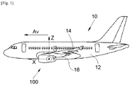
- the Fig. 1 shows an aircraft 10 which comprises a fuselage 12 on each side of which is fixed a wing 14 which carries at least one bypass turbojet 100 according to the invention.
- the bypass turbojet 100 is fixed under the wing 14 by means of a mast 16.
- the longitudinal axis of the bypass turbojet 100 which is parallel is called X.
- the longitudinal axis of the aircraft 10 and which is oriented positively in the direction of travel of the aircraft 10 the transverse axis of the bypass turbojet 100 which is horizontal when the aircraft is on the ground is called Y, and Z the vertical axis when the aircraft is on the ground, these three directions X, Y and Z being orthogonal to each other.
- the terms “front” and “rear” are to be considered in relation to the direction of movement of the aircraft, shown by an arrow Av on the Fig. 1 .
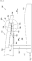
- the Figs. 2 and 3 show the bypass turbojet 100 which comprises a nacelle 102 and an engine which is housed inside the nacelle 102.
- the bypass turbojet 100 has a duct 202 between the nacelle 102 and the engine in which the secondary flow 208 circulates.
- the engine is materialized here by its cowling 103.
- the nacelle 102 comprises at least one blocking door 104.
- Each locking door 104 makes it possible, depending on its position, to reverse the thrust of the bypass turbojet 100.
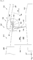
- the nacelle 102 has for each locking door 104, an opening 210 ( Fig. 3 ) open between the vein 202 and the outside of the nacelle 102.
- the nacelle 102 has a fixed cowl 206 which delimits the opening 210 forward with respect to the longitudinal axis X and which is fixedly mounted on a fixed structure 101 of the nacelle 102.
- the nacelle 102 has a movable cowl 207 which delimits the opening 210 behind relative to the longitudinal axis X.
- the movable cowl 207 is mounted movable in translation in a direction of translation generally parallel to the longitudinal axis X on the structure. fixed 101 and therefore relative to the fixed cover 206.
- the translation is carried out by any suitable means such as for example slides.
- the fixed cowl 206 and the movable cowl 207 each have an exterior surface which constitutes the exterior envelope of the nacelle 102 and an interior surface which constitutes an exterior wall of the duct 202.
- the cowling 103 of the engine constitutes an interior wall of the duct. 202.
- the movable cover 207 is movable between a closed position ( Fig. 2 ) in which it is brought closer to the fixed cover 206 and an open position ( Fig. 3 ) in which it is moved away from the fixed cover 206 towards the rear so as to widen the opening 210.
- the direction of movement from the closed position to the open position is represented by the arrow 52.
- the nacelle 102 also comprises motor means for moving the movable cowl 207 from the closed position to the open position and vice versa, and they may comprise, for example jacks, ball screws, motors or any other suitable means for moving an element in translation.
- the motor means are controlled by a control unit, of the processor type, which controls, for example, the lengthening and shortening of the jacks according to the needs of the aircraft 10.
- the locking door 104 is mounted so as to be able to rotate about an axis of rotation 50 on the movable cover 207 between a retracted position ( Fig. 2 ) and a deployed position ( Fig. 3 ) for which the reverse thrust has maximum efficiency.
- the axis of rotation 50 is perpendicular to the longitudinal axis X.
- the axis of rotation 50 is here at the level of the front edge of the locking door 104.
- the direction of rotation between the retracted position and the deployed position is shown by arrow 54.
- the axis of rotation 50 is in a plane substantially perpendicular to a radial direction with respect to the longitudinal axis X.
- the blocking door 104 In the retracted position, the blocking door 104 is positioned outside the duct 202. In the open position, the movable cover 207 is moved rearward to facilitate the operation of the blocking door 104 which passes from the retracted position. in the deployed position.
- the blocking door 104 When the blocking door 104 is in the deployed position, the blocking door 104 comes across the vein 202 and deflects at least part of the secondary flow 208 outwardly through the opening 210. In the deployed position, the edge free from the blocking door 104 approaches the cowling 103 of the engine. On the Fig. 3 , the blocking door 104 is lowered to the deployed position.
- the passage from the retracted position to the deployed position of the locking door 104 is coordinated and deferred with respect to the passage from the closed position to the open position of the movable cowl 207 and vice versa.
- the rotation of the locking door 104 begins when the movable cover 207 passes through an intermediate position between the closed position and the open position. Conversely, when passing from the deployed position to the retracted position, the rotation of the locking door 104 stops when the cover mobile 207 passes through the intermediate position by returning from the open position to the closed position.
- a deployment system 150, 650 This coordination and this shift are ensured by a deployment system 150, 650.
- the Figs. 4 and 5 show a deployment system 150 according to a first embodiment of the invention, and the Figs. 6 and 7 show a deployment system 650 according to a second embodiment of the invention.
- the slide 156 remains guided by the guide system 152 throughout the maneuver from the closed / retracted position to the open / deployed position and vice versa.
- the deployment system 150, 650 thus remains outside the vein 202.
- the deployment system 150, 650 is disposed behind the axis of rotation 50 and the locking door 104 and outwardly relative to the vein 202, that is to say generally in the cover. mobile 207.
- the guide system 152 is a groove in which the slide 156 moves and the groove is here closed at its rear end to prevent the exit of the slide 156 and then facilitates rotation when the slide 156 reaches the closed rear end.
- the position of the closed rear end is then defined so that the slide 156 arrives against the closed rear end at the same time as the stop 154 arrives against the cam 158, 658.
- the articulation of the arm 162 on the locking door 104 is disposed on the rear face of said blocking door 104, that is to say the face oriented towards the rear when the blocking door 104 is in the deployed position.
- the stop 154 again follows the cam 158, 658 but in the opposite direction so as to return the arm 162 to the initial position by rotation around the slide 156 and the blocking door 104 in its retracted position. Then, the stopper 154 is released from the cam 158, 658 and the slide 156 moves along the guide system 152 to return to the closed position.
- the intermediate position corresponds here to the moment when the stop 154 comes into contact with the cam 158, 658 or leaves the contact of the cam 158, 658.
- the cam 158 is fixedly mounted on the fixed structure 101 and comprises an arcuate groove which is generally centered on the axis of deployment 160 when the stop 154 arrives against the cam 158 .
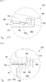
- the cam 658 is mounted so as to be able to rotate on the fixed structure 101 about a beat axis 660 parallel to the axis of rotation 50.
- the cam 658 has a first L-shaped groove 662 of which a first branch is generally parallel to the longitudinal axis X and a second branch of which is generally radial with respect to the longitudinal axis X.
- the stopper 154 first moves out of the first groove 662, then along the first leg and comes into contact with the second leg ( Fig. 6 ) and the continuation of the translation of the movable cowl 207 towards the open position causes the tilting of the cam 658 around its flapping axis 660 and the displacement of the stop 154 along the second branch ( Fig. 7 ), which causes the rotation of the arm 162 around the slide 156 and the displacement of the locking door 104 in the deployed position.
- Cam 658 then passes from a first position ( Fig. 6 ) corresponding to the retracted position to a second position ( Fig. 7 ) corresponding to the deployed position. Reverse movement allows the return to the closed / retracted position.
- the deployment system 650 also includes a return element 664 which forces the cam 658 into the first position corresponding to the retracted position.
- the return element 664 is a tension spring fixed between the fixed structure 101 and the cam 658. The return element 664 facilitates the return of the cam 658 to the first position when moving from the open position. towards the closed position.
- the cam 658 abuts against the fixed structure 101 at the level of a bearing surface 666.
- the deployment axis 660 is here outside and behind the second branch.
- Cam 658 also has a second arcuate groove 667 centered on deployment axis 660 and slider 156 is arranged to move in second groove 667 when cam 658 is pivoted between the first position (from position intermediate) and the second position corresponding to the deployed position.
- the introduction of the slide 156 into the second groove 667 additionally blocks the retreat of the arm 162.
Landscapes
- Engineering & Computer Science (AREA)
- Chemical & Material Sciences (AREA)
- Combustion & Propulsion (AREA)
- Mechanical Engineering (AREA)
- General Engineering & Computer Science (AREA)
- Aviation & Aerospace Engineering (AREA)
- Structures Of Non-Positive Displacement Pumps (AREA)
Applications Claiming Priority (1)
| Application Number | Priority Date | Filing Date | Title |
|---|---|---|---|
| FR1901603A FR3092819A1 (fr) | 2019-02-18 | 2019-02-18 | Nacelle d’un turboreacteur comportant une porte de blocage et un systeme de deploiement de la porte de blocage |
Publications (2)
| Publication Number | Publication Date |
|---|---|
| EP3696397A1 true EP3696397A1 (de) | 2020-08-19 |
| EP3696397B1 EP3696397B1 (de) | 2021-11-10 |
Family
ID=67441271
Family Applications (1)
| Application Number | Title | Priority Date | Filing Date |
|---|---|---|---|
| EP20156733.6A Active EP3696397B1 (de) | 2019-02-18 | 2020-02-11 | Gondel eines turboreaktors, die eine blockiertür und ein system zum einsatz einer solchen blockiertür umfasst |
Country Status (4)
| Country | Link |
|---|---|
| US (1) | US11193450B2 (de) |
| EP (1) | EP3696397B1 (de) |
| CN (1) | CN111572786B (de) |
| FR (1) | FR3092819A1 (de) |
Families Citing this family (3)
| Publication number | Priority date | Publication date | Assignee | Title |
|---|---|---|---|---|
| EP4063255B1 (de) * | 2021-03-25 | 2023-05-03 | Airbus Operations (S.A.S.) | Luftfahrzeugverkleidung mit mindestens einem flexiblen gelenk, das eine feste und eine bewegliche platte verbindet |
| US11692509B2 (en) * | 2021-07-08 | 2023-07-04 | Rohr, Inc. | Hidden drag link for thrust reverser assembly |
| US12372046B2 (en) | 2023-03-06 | 2025-07-29 | Rohr, Inc. | Thrust reverser with blocker door lock |
Citations (5)
| Publication number | Priority date | Publication date | Assignee | Title |
|---|---|---|---|---|
| GB1303875A (de) * | 1970-04-02 | 1973-01-24 | ||
| GB2045179A (en) | 1979-03-30 | 1980-10-29 | Gen Electric | Thrust reverser for a long duct fan engine |
| US20060185464A1 (en) * | 2005-02-22 | 2006-08-24 | Borgwarner Inc. | Rotary actuator |
| US20120079805A1 (en) * | 2010-09-30 | 2012-04-05 | Alan Roy Stuart | Thrust reverser assembly |
| EP3379068A1 (de) * | 2017-03-22 | 2018-09-26 | Airbus Operations S.A.S. | Maschinengondel eines strahltriebwerks, die eine schubumkehrklappe umfasst |
Family Cites Families (10)
| Publication number | Priority date | Publication date | Assignee | Title |
|---|---|---|---|---|
| US3503211A (en) * | 1968-04-10 | 1970-03-31 | Rohr Corp | Thrust reverser |
| US3511055A (en) * | 1968-05-29 | 1970-05-12 | Rohr Corp | Thrust reverser |
| US4767055A (en) * | 1987-03-27 | 1988-08-30 | United Technologies Corporation | Method and linkage for positioning a convergent flap and coaxial arc valve |
| US4828173A (en) * | 1987-05-22 | 1989-05-09 | United Technologies Corporation | Area controlled, thrust vectoring vane cascade |
| US5243817A (en) * | 1990-07-05 | 1993-09-14 | Rohr, Inc. | Thrust reverser for fan jet aircraft engines |
| FR2930973B1 (fr) * | 2008-05-06 | 2010-04-23 | Airbus France | Procede et dispositif de mise en oeuvre des inverseurs de poussee d'un aeronef |
| EP3000734B1 (de) * | 2014-09-29 | 2018-03-14 | Airbus Defence and Space, S.A. | Ausrichtungs- und Sicherheitsvorrichtung für die Hauben von Flugzeugtriebwerksgondeln |
| EP3034848B1 (de) * | 2014-12-15 | 2018-08-29 | United Technologies Corporation | Gasturbinenmotor und schubumkehranordnung dafür |
| US10077740B2 (en) * | 2015-10-16 | 2018-09-18 | The Boeing Company | Folding door thrust reversers for aircraft engines |
| FR3059368A1 (fr) * | 2016-11-28 | 2018-06-01 | Airbus Operations | Nacelle d'un turboreacteur comportant un volet inverseur |
-
2019
- 2019-02-18 FR FR1901603A patent/FR3092819A1/fr not_active Ceased
-
2020
- 2020-02-11 EP EP20156733.6A patent/EP3696397B1/de active Active
- 2020-02-14 US US16/791,372 patent/US11193450B2/en active Active
- 2020-02-17 CN CN202010095746.0A patent/CN111572786B/zh active Active
Patent Citations (5)
| Publication number | Priority date | Publication date | Assignee | Title |
|---|---|---|---|---|
| GB1303875A (de) * | 1970-04-02 | 1973-01-24 | ||
| GB2045179A (en) | 1979-03-30 | 1980-10-29 | Gen Electric | Thrust reverser for a long duct fan engine |
| US20060185464A1 (en) * | 2005-02-22 | 2006-08-24 | Borgwarner Inc. | Rotary actuator |
| US20120079805A1 (en) * | 2010-09-30 | 2012-04-05 | Alan Roy Stuart | Thrust reverser assembly |
| EP3379068A1 (de) * | 2017-03-22 | 2018-09-26 | Airbus Operations S.A.S. | Maschinengondel eines strahltriebwerks, die eine schubumkehrklappe umfasst |
Also Published As
| Publication number | Publication date |
|---|---|
| CN111572786A (zh) | 2020-08-25 |
| CN111572786B (zh) | 2023-04-11 |
| US20200263632A1 (en) | 2020-08-20 |
| US11193450B2 (en) | 2021-12-07 |
| EP3696397B1 (de) | 2021-11-10 |
| FR3092819A1 (fr) | 2020-08-21 |
Similar Documents
| Publication | Publication Date | Title |
|---|---|---|
| EP3354577B1 (de) | Strahltriebwerkgondel, die eine schubumkehrklappe umfasst | |
| EP3421771B1 (de) | Turbotriebwerk, das eine mit schubumkehrklappen ausgestattete gondel umfasst | |
| EP3309380B1 (de) | Gasturbinentriebwerksgondel umfassend eine schubumkehrklappe | |
| EP0365425A1 (de) | Schubumkehrvorrichtung mit im Drehpunkt gelagerten Schwenkklappen | |
| EP3696397B1 (de) | Gondel eines turboreaktors, die eine blockiertür und ein system zum einsatz einer solchen blockiertür umfasst | |
| CA2239462C (fr) | Inverseur de poussee de turboreacteur a portes munies d'un becquet mobile a entrainement optimise | |
| EP3715613A1 (de) | Doppelstrom-turbotriebwerk, das eine reihe von rotierenden schaufelblättern umfasst, um den kanal des sekundärstroms abzudichten | |
| EP3647202B1 (de) | Turbotriebwerk-anordnung eines luftfahrzeugs, die einen scharnierdeckel umfasst | |
| EP3726037B1 (de) | Doppelfluss-turbotriebwerk, das eine reihe von rotierenden schaufelblättern umfasst, um den kanal des sekundärstroms abzudichten | |
| FR3095015A1 (fr) | Turboreacteur double flux comportant une serie de lames rotatives pour obturer la veine du flux secondaire | |
| EP3327274B1 (de) | Turbotriebwerksgondeln umfassend eine umkehrklappe und eine zusätzliche klappe | |
| EP3530926A1 (de) | Maschinengondel eines strahltriebwerks, die eine schubumkehrklappe umfasst | |
| EP0821151A1 (de) | Schubumkehrvorrichtung für ein Strahltriebwerk mit Klappen mit verschiebbarem Wandteil | |
| EP3379068B1 (de) | Maschinengondel eines strahltriebwerks, die eine schubumkehrklappe umfasst | |
| EP3521603B1 (de) | Nacelle eines turbojet-motors mit einer aussenschubumkehrtür | |
| EP4361429B1 (de) | Turbofantriebwerk mit beweglichen ablenkplatten und einem system zur betätigung der deflektoren | |
| EP3670883B1 (de) | Gondel eines turbotriebwerks, umfassend eine umschaltklappe und ein system zur verzögerten auslösung | |
| EP3696088B1 (de) | Gondel eines turboreaktors, die eine blockiertür und ein system zum einsatz einer solchen blockiertür umfasst | |
| EP3461744A1 (de) | Schubumkehrertriebwerk für flugzeug mit verbesserter öffnung | |
| FR3089206A1 (fr) | Nacelle d’un turboreacteur comportant un volet inverseur et un systeme de deploiement a retardement | |
| EP3620371A1 (de) | Gondel für einen luftfahrzeugmotor, die mit mitteln zur verhinderung der deformation der mit gelenken versehenen gebläsedeckel ausgestattet ist | |
| FR3066232A1 (fr) | Nacelle d'un turboreacteur comportant un volet inverseur | |
| FR3066231A1 (fr) | Nacelle d'un turboreacteur comportant un volet inverseur | |
| EP3680177A1 (de) | Gondel eines turboreaktors, die eine umkehrbare tür und ein hilfssystem zum einsatz einer solchen umkehrbaren tür umfasst | |
| FR3128207A1 (fr) | Turboréacteur double flux comportant des déflecteurs mobiles et un système d’actionnement des déflecteurs |
Legal Events
| Date | Code | Title | Description |
|---|---|---|---|
| PUAI | Public reference made under article 153(3) epc to a published international application that has entered the european phase |
Free format text: ORIGINAL CODE: 0009012 |
|
| STAA | Information on the status of an ep patent application or granted ep patent |
Free format text: STATUS: THE APPLICATION HAS BEEN PUBLISHED |
|
| AK | Designated contracting states |
Kind code of ref document: A1 Designated state(s): AL AT BE BG CH CY CZ DE DK EE ES FI FR GB GR HR HU IE IS IT LI LT LU LV MC MK MT NL NO PL PT RO RS SE SI SK SM TR |
|
| AX | Request for extension of the european patent |
Extension state: BA ME |
|
| RIN1 | Information on inventor provided before grant (corrected) |
Inventor name: CAZEAUX, LAURENT Inventor name: ORTEU, BENOIT Inventor name: GANAPATHI RAJU, SREEKANTH Inventor name: DENOY, OLIVIER |
|
| RIN1 | Information on inventor provided before grant (corrected) |
Inventor name: DENOY, OLIVIER Inventor name: ORTEU, BENOIT Inventor name: GANAPATHI RAJU, SREEKANTH Inventor name: CAZEAUX, LAURENT |
|
| STAA | Information on the status of an ep patent application or granted ep patent |
Free format text: STATUS: REQUEST FOR EXAMINATION WAS MADE |
|
| 17P | Request for examination filed |
Effective date: 20210204 |
|
| RBV | Designated contracting states (corrected) |
Designated state(s): AL AT BE BG CH CY CZ DE DK EE ES FI FR GB GR HR HU IE IS IT LI LT LU LV MC MK MT NL NO PL PT RO RS SE SI SK SM TR |
|
| GRAP | Despatch of communication of intention to grant a patent |
Free format text: ORIGINAL CODE: EPIDOSNIGR1 |
|
| STAA | Information on the status of an ep patent application or granted ep patent |
Free format text: STATUS: GRANT OF PATENT IS INTENDED |
|
| RIC1 | Information provided on ipc code assigned before grant |
Ipc: F02K 1/72 20060101AFI20210512BHEP |
|
| INTG | Intention to grant announced |
Effective date: 20210609 |
|
| GRAS | Grant fee paid |
Free format text: ORIGINAL CODE: EPIDOSNIGR3 |
|
| GRAA | (expected) grant |
Free format text: ORIGINAL CODE: 0009210 |
|
| STAA | Information on the status of an ep patent application or granted ep patent |
Free format text: STATUS: THE PATENT HAS BEEN GRANTED |
|
| AK | Designated contracting states |
Kind code of ref document: B1 Designated state(s): AL AT BE BG CH CY CZ DE DK EE ES FI FR GB GR HR HU IE IS IT LI LT LU LV MC MK MT NL NO PL PT RO RS SE SI SK SM TR |
|
| REG | Reference to a national code |
Ref country code: GB Ref legal event code: FG4D Free format text: NOT ENGLISH |
|
| REG | Reference to a national code |
Ref country code: AT Ref legal event code: REF Ref document number: 1446312 Country of ref document: AT Kind code of ref document: T Effective date: 20211115 Ref country code: CH Ref legal event code: EP |
|
| REG | Reference to a national code |
Ref country code: DE Ref legal event code: R096 Ref document number: 602020000934 Country of ref document: DE |
|
| REG | Reference to a national code |
Ref country code: IE Ref legal event code: FG4D Free format text: LANGUAGE OF EP DOCUMENT: FRENCH |
|
| REG | Reference to a national code |
Ref country code: LT Ref legal event code: MG9D |
|
| REG | Reference to a national code |
Ref country code: NL Ref legal event code: MP Effective date: 20211110 |
|
| REG | Reference to a national code |
Ref country code: AT Ref legal event code: MK05 Ref document number: 1446312 Country of ref document: AT Kind code of ref document: T Effective date: 20211110 |
|
| PG25 | Lapsed in a contracting state [announced via postgrant information from national office to epo] |
Ref country code: RS Free format text: LAPSE BECAUSE OF FAILURE TO SUBMIT A TRANSLATION OF THE DESCRIPTION OR TO PAY THE FEE WITHIN THE PRESCRIBED TIME-LIMIT Effective date: 20211110 Ref country code: LT Free format text: LAPSE BECAUSE OF FAILURE TO SUBMIT A TRANSLATION OF THE DESCRIPTION OR TO PAY THE FEE WITHIN THE PRESCRIBED TIME-LIMIT Effective date: 20211110 Ref country code: FI Free format text: LAPSE BECAUSE OF FAILURE TO SUBMIT A TRANSLATION OF THE DESCRIPTION OR TO PAY THE FEE WITHIN THE PRESCRIBED TIME-LIMIT Effective date: 20211110 Ref country code: BG Free format text: LAPSE BECAUSE OF FAILURE TO SUBMIT A TRANSLATION OF THE DESCRIPTION OR TO PAY THE FEE WITHIN THE PRESCRIBED TIME-LIMIT Effective date: 20220210 Ref country code: AT Free format text: LAPSE BECAUSE OF FAILURE TO SUBMIT A TRANSLATION OF THE DESCRIPTION OR TO PAY THE FEE WITHIN THE PRESCRIBED TIME-LIMIT Effective date: 20211110 |
|
| PG25 | Lapsed in a contracting state [announced via postgrant information from national office to epo] |
Ref country code: IS Free format text: LAPSE BECAUSE OF FAILURE TO SUBMIT A TRANSLATION OF THE DESCRIPTION OR TO PAY THE FEE WITHIN THE PRESCRIBED TIME-LIMIT Effective date: 20220310 Ref country code: SE Free format text: LAPSE BECAUSE OF FAILURE TO SUBMIT A TRANSLATION OF THE DESCRIPTION OR TO PAY THE FEE WITHIN THE PRESCRIBED TIME-LIMIT Effective date: 20211110 Ref country code: PT Free format text: LAPSE BECAUSE OF FAILURE TO SUBMIT A TRANSLATION OF THE DESCRIPTION OR TO PAY THE FEE WITHIN THE PRESCRIBED TIME-LIMIT Effective date: 20220310 Ref country code: PL Free format text: LAPSE BECAUSE OF FAILURE TO SUBMIT A TRANSLATION OF THE DESCRIPTION OR TO PAY THE FEE WITHIN THE PRESCRIBED TIME-LIMIT Effective date: 20211110 Ref country code: NO Free format text: LAPSE BECAUSE OF FAILURE TO SUBMIT A TRANSLATION OF THE DESCRIPTION OR TO PAY THE FEE WITHIN THE PRESCRIBED TIME-LIMIT Effective date: 20220210 Ref country code: NL Free format text: LAPSE BECAUSE OF FAILURE TO SUBMIT A TRANSLATION OF THE DESCRIPTION OR TO PAY THE FEE WITHIN THE PRESCRIBED TIME-LIMIT Effective date: 20211110 Ref country code: LV Free format text: LAPSE BECAUSE OF FAILURE TO SUBMIT A TRANSLATION OF THE DESCRIPTION OR TO PAY THE FEE WITHIN THE PRESCRIBED TIME-LIMIT Effective date: 20211110 Ref country code: HR Free format text: LAPSE BECAUSE OF FAILURE TO SUBMIT A TRANSLATION OF THE DESCRIPTION OR TO PAY THE FEE WITHIN THE PRESCRIBED TIME-LIMIT Effective date: 20211110 Ref country code: GR Free format text: LAPSE BECAUSE OF FAILURE TO SUBMIT A TRANSLATION OF THE DESCRIPTION OR TO PAY THE FEE WITHIN THE PRESCRIBED TIME-LIMIT Effective date: 20220211 |
|
| PG25 | Lapsed in a contracting state [announced via postgrant information from national office to epo] |
Ref country code: SM Free format text: LAPSE BECAUSE OF FAILURE TO SUBMIT A TRANSLATION OF THE DESCRIPTION OR TO PAY THE FEE WITHIN THE PRESCRIBED TIME-LIMIT Effective date: 20211110 Ref country code: SK Free format text: LAPSE BECAUSE OF FAILURE TO SUBMIT A TRANSLATION OF THE DESCRIPTION OR TO PAY THE FEE WITHIN THE PRESCRIBED TIME-LIMIT Effective date: 20211110 Ref country code: RO Free format text: LAPSE BECAUSE OF FAILURE TO SUBMIT A TRANSLATION OF THE DESCRIPTION OR TO PAY THE FEE WITHIN THE PRESCRIBED TIME-LIMIT Effective date: 20211110 Ref country code: ES Free format text: LAPSE BECAUSE OF FAILURE TO SUBMIT A TRANSLATION OF THE DESCRIPTION OR TO PAY THE FEE WITHIN THE PRESCRIBED TIME-LIMIT Effective date: 20211110 Ref country code: EE Free format text: LAPSE BECAUSE OF FAILURE TO SUBMIT A TRANSLATION OF THE DESCRIPTION OR TO PAY THE FEE WITHIN THE PRESCRIBED TIME-LIMIT Effective date: 20211110 Ref country code: DK Free format text: LAPSE BECAUSE OF FAILURE TO SUBMIT A TRANSLATION OF THE DESCRIPTION OR TO PAY THE FEE WITHIN THE PRESCRIBED TIME-LIMIT Effective date: 20211110 Ref country code: CZ Free format text: LAPSE BECAUSE OF FAILURE TO SUBMIT A TRANSLATION OF THE DESCRIPTION OR TO PAY THE FEE WITHIN THE PRESCRIBED TIME-LIMIT Effective date: 20211110 |
|
| REG | Reference to a national code |
Ref country code: DE Ref legal event code: R097 Ref document number: 602020000934 Country of ref document: DE |
|
| REG | Reference to a national code |
Ref country code: DE Ref legal event code: R119 Ref document number: 602020000934 Country of ref document: DE |
|
| PLBE | No opposition filed within time limit |
Free format text: ORIGINAL CODE: 0009261 |
|
| STAA | Information on the status of an ep patent application or granted ep patent |
Free format text: STATUS: NO OPPOSITION FILED WITHIN TIME LIMIT |
|
| PG25 | Lapsed in a contracting state [announced via postgrant information from national office to epo] |
Ref country code: MC Free format text: LAPSE BECAUSE OF FAILURE TO SUBMIT A TRANSLATION OF THE DESCRIPTION OR TO PAY THE FEE WITHIN THE PRESCRIBED TIME-LIMIT Effective date: 20211110 |
|
| 26N | No opposition filed |
Effective date: 20220811 |
|
| REG | Reference to a national code |
Ref country code: BE Ref legal event code: MM Effective date: 20220228 |
|
| PG25 | Lapsed in a contracting state [announced via postgrant information from national office to epo] |
Ref country code: LU Free format text: LAPSE BECAUSE OF NON-PAYMENT OF DUE FEES Effective date: 20220211 Ref country code: AL Free format text: LAPSE BECAUSE OF FAILURE TO SUBMIT A TRANSLATION OF THE DESCRIPTION OR TO PAY THE FEE WITHIN THE PRESCRIBED TIME-LIMIT Effective date: 20211110 |
|
| PG25 | Lapsed in a contracting state [announced via postgrant information from national office to epo] |
Ref country code: SI Free format text: LAPSE BECAUSE OF FAILURE TO SUBMIT A TRANSLATION OF THE DESCRIPTION OR TO PAY THE FEE WITHIN THE PRESCRIBED TIME-LIMIT Effective date: 20211110 |
|
| PG25 | Lapsed in a contracting state [announced via postgrant information from national office to epo] |
Ref country code: IE Free format text: LAPSE BECAUSE OF NON-PAYMENT OF DUE FEES Effective date: 20220211 Ref country code: DE Free format text: LAPSE BECAUSE OF NON-PAYMENT OF DUE FEES Effective date: 20220901 |
|
| PG25 | Lapsed in a contracting state [announced via postgrant information from national office to epo] |
Ref country code: BE Free format text: LAPSE BECAUSE OF NON-PAYMENT OF DUE FEES Effective date: 20220228 |
|
| PG25 | Lapsed in a contracting state [announced via postgrant information from national office to epo] |
Ref country code: IT Free format text: LAPSE BECAUSE OF FAILURE TO SUBMIT A TRANSLATION OF THE DESCRIPTION OR TO PAY THE FEE WITHIN THE PRESCRIBED TIME-LIMIT Effective date: 20211110 |
|
| REG | Reference to a national code |
Ref country code: CH Ref legal event code: PL |
|
| PG25 | Lapsed in a contracting state [announced via postgrant information from national office to epo] |
Ref country code: LI Free format text: LAPSE BECAUSE OF NON-PAYMENT OF DUE FEES Effective date: 20230228 Ref country code: CH Free format text: LAPSE BECAUSE OF NON-PAYMENT OF DUE FEES Effective date: 20230228 |
|
| PG25 | Lapsed in a contracting state [announced via postgrant information from national office to epo] |
Ref country code: MK Free format text: LAPSE BECAUSE OF FAILURE TO SUBMIT A TRANSLATION OF THE DESCRIPTION OR TO PAY THE FEE WITHIN THE PRESCRIBED TIME-LIMIT Effective date: 20211110 Ref country code: CY Free format text: LAPSE BECAUSE OF FAILURE TO SUBMIT A TRANSLATION OF THE DESCRIPTION OR TO PAY THE FEE WITHIN THE PRESCRIBED TIME-LIMIT Effective date: 20211110 |
|
| PG25 | Lapsed in a contracting state [announced via postgrant information from national office to epo] |
Ref country code: HU Free format text: LAPSE BECAUSE OF FAILURE TO SUBMIT A TRANSLATION OF THE DESCRIPTION OR TO PAY THE FEE WITHIN THE PRESCRIBED TIME-LIMIT; INVALID AB INITIO Effective date: 20200211 |
|
| PG25 | Lapsed in a contracting state [announced via postgrant information from national office to epo] |
Ref country code: TR Free format text: LAPSE BECAUSE OF FAILURE TO SUBMIT A TRANSLATION OF THE DESCRIPTION OR TO PAY THE FEE WITHIN THE PRESCRIBED TIME-LIMIT Effective date: 20211110 |
|
| PG25 | Lapsed in a contracting state [announced via postgrant information from national office to epo] |
Ref country code: MT Free format text: LAPSE BECAUSE OF FAILURE TO SUBMIT A TRANSLATION OF THE DESCRIPTION OR TO PAY THE FEE WITHIN THE PRESCRIBED TIME-LIMIT Effective date: 20211110 |
|
| PGFP | Annual fee paid to national office [announced via postgrant information from national office to epo] |
Ref country code: GB Payment date: 20260220 Year of fee payment: 7 |
|
| PGFP | Annual fee paid to national office [announced via postgrant information from national office to epo] |
Ref country code: FR Payment date: 20260218 Year of fee payment: 7 |