EP0465375A2 - Dispositif et méthode de traitement d'image pour la reconnaissance d'objets en mouvement et télémètre - Google Patents
Dispositif et méthode de traitement d'image pour la reconnaissance d'objets en mouvement et télémètre Download PDFInfo
- Publication number
- EP0465375A2 EP0465375A2 EP91401873A EP91401873A EP0465375A2 EP 0465375 A2 EP0465375 A2 EP 0465375A2 EP 91401873 A EP91401873 A EP 91401873A EP 91401873 A EP91401873 A EP 91401873A EP 0465375 A2 EP0465375 A2 EP 0465375A2
- Authority
- EP
- European Patent Office
- Prior art keywords
- video data
- video
- image
- memory
- standard image
- Prior art date
- Legal status (The legal status is an assumption and is not a legal conclusion. Google has not performed a legal analysis and makes no representation as to the accuracy of the status listed.)
- Withdrawn
Links
Images


Classifications
-
- G—PHYSICS
- G06—COMPUTING OR CALCULATING; COUNTING
- G06T—IMAGE DATA PROCESSING OR GENERATION, IN GENERAL
- G06T1/00—General purpose image data processing
-
- H—ELECTRICITY
- H04—ELECTRIC COMMUNICATION TECHNIQUE
- H04N—PICTORIAL COMMUNICATION, e.g. TELEVISION
- H04N5/00—Details of television systems
- H04N5/14—Picture signal circuitry for video frequency region
- H04N5/144—Movement detection
-
- G—PHYSICS
- G01—MEASURING; TESTING
- G01S—RADIO DIRECTION-FINDING; RADIO NAVIGATION; DETERMINING DISTANCE OR VELOCITY BY USE OF RADIO WAVES; LOCATING OR PRESENCE-DETECTING BY USE OF THE REFLECTION OR RERADIATION OF RADIO WAVES; ANALOGOUS ARRANGEMENTS USING OTHER WAVES
- G01S11/00—Systems for determining distance or velocity not using reflection or reradiation
- G01S11/12—Systems for determining distance or velocity not using reflection or reradiation using electromagnetic waves other than radio waves
Definitions
- the present invention pertains to equipment and methods for image processing, and more particularly, to image processing equipment and methods suitable for detecting moving objects and for assessment of complex visual fields containing moving objects, including assessment of the distance between a moving object and a reference point in such a visual field.
- Video cameras offer a number of advantages as input devices for systems which rely on visual data. They are lightweight, relatively inexpensive and can be used in a variety of hostile environments which humans tolerate poorly, or not at all. Video cameras find wide application in security and surveillance systems, for process control, assembly control, customer and personnel monitoring, as well as for many other uses. For example, by means of a television system, one guard can monitor an extensive area, indoors and outdoors, from a climate controlled room. When real time monitoring is unnecessary, video signals from one or more cameras can simply be recorded on magnetic tape and viewed later as the need arises.
- One additional drawback of conventional motion detecting and monitoring devices and methods is that generally a single video camera is used for each visual field, for which reason only two dimensional data is provided. Accordingly, when distance factors are of importance, these systems tend to be inadequate. When monitoring hazardous areas, for example, when someone appears to be approaching the point of danger, distance data is helpful for evaluating the urgency of a response to the situation, a feature which the conventional devices do not offer.
- an object of the present invention to provide an image processing method and device which is capable of reliably and selectively detecting a target moving object, and which can do so even when the background is complex and in motion. Furthermore, it is an object of the present invention to provide a totally nonmechanical rangefinding device based on the above described image processing method and device.
- the present invention is based on analytical methods for stochastic processes.
- Actual visual image data consists a set of values as a function of both time and location, each value corresponding to visual data such as brightness of a predetermined location at a predetermined time.
- a moving object is recognized as a remarkabe deviation of data from standard along the time axis.
- the standard visual image is obtained by averaging visual images obtained during a period of time which is determined according to the probabilistic characteristics of both the visual image and expected event to be detected. This method is practical especially when the visual image is stationary or approximately stationary because it is expected in such a case that any normal event should fall within a predictable distribution which is obtained by a certain period of time preceeding the event.
- An event which is out of the predictable probabilistic distribution is a moving object in a stationary background, for example.
- the present invention provides an image processing method for detecting moving objects comprising the steps of:
- an image processing device for detecting moving objects comprising:
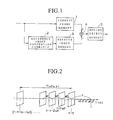
- a block diagram can be seen illustrating the overall layout the device of the present embodiment.
- An image processing method in accordance with the present invention serves as a basis for general operation of the device shown in Fig. 1, the time sequence of which is schematically illustrated in the time chart of Fig. 2.
- a standard image generation circuit 2 can be seen to which data derived from the output signal of a video camera focussed on a given visual field is sequentially supplied, one video frame at a time, at a frame interval given by ⁇ t.
- the output signal of standard image generation circuit 2 at time t corresponds to a composite standard image S t , which represents the result of averaging n consecutive video frames supplied t minutes previously to standard image generation circuit 2, at a frame interval given by ⁇ , where ⁇ ⁇ ⁇ t.
- Composite standard image S t represents an image of static elements in the visual field, that is, composite standard image S t represents the nonmoving background from which images of moving objects in the visual field have been eliminated through the averaging operation. Subtracting composite standard image S t from the current video frame captured at time t results in an image showing only objects which can be considered as foreign objects in the visual field at time t, that is, objects which are not part of the static background..
- a video frame captured at current time t expressed as an i by j matrix of pixel values is converted to a vector representation thereof, as given by D, j (d, j , t) which is then stored in current frame memory 1, shown in Fig. 1.
- the vector representation of composite standard image S t as given by S, j (s, j , t), which will subsequently be subtracted in subtractor 4 from the current matrix stored in current frame memory 1 is stored in standard image memory 3.
- each pixel of the resulting vector representation S ij (s ij , t) is given as shown in Equ. 1 below:
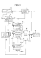
- the above mentioned fundamental clock signal CL is supplied to a frame memory address counter 11, wherein an address signal AD and a frame signal FR are generated in concert with the supplied clock signal.
- Address signal AD sequentially output from frame memory address counter 11 is then supplied to current frame memory 1 and to frame memory units 15 i through 15 n which will be described below, and frame signal FR is sequentially supplied to a frame selection counter 12.
- frame selection counter 12 According to frame signal FR supplied from frame memory address counter 11, frame selection counter 12 generates selector signals CS 1 through CS n , each of which is supplied to a corresponding gate 13 1 through 13 n , and a control signal CD which is supplied to a selection circuit 16.
- any signal among selector signals CS 1 through CS n which has a high level value results in the opening of the corresponding gate 13 i , with the result that the output signal of the corresponding frame memory unit 15 is supplied to the corresponding adder 14 1 .
- the digital current video signal from A/D converter 10 is supplied to each of adders 14 1 through 14 n , and address signal AD from frame memory address counter 11 is supplied to each of memory units 15 1 through 15 n .
- control signal CD output from frame selection counter 12 is supplied to a selection circuit 16.
- the output csignal of one of frame memory units 15 1 through 15 n is output via selection circuit 16 and supplied to a multiplier 17.
- multiplier 17 the supplied value is muliplied by 1/n, the result of which is supplied to a subtractor 18 which also receives an output signal from current frame memory 1.
- the value supplied to subtractor 18 from multiplier 17 is subtracted from the value supplied from current frame memory 1, thereby obtaining video data R which is then stored in moving object memory 19.
- the current output signal of the video camera employed is converted to a digital video signal A in A/D converter 10, the result of which is stored in current frame memory 1 and supplied to adders 14 1 , 14 2 and 14 3 .
- selector signal CS 1 supplied from frame selection counter 12 to gate 13 1 is low, as is shown in Fig. 4(b), for which reason digital video signal A in adder 14 1 is stored without change in memory unit 15 1 at the memory location therein indexed by address signal AD from frame memory address counter 11, as shown in Fig.
- selector signals CS 2 and CS 3 are high, during initialization there is no preexisting video data for composite standard image S since the device has just been activated. As a result, the addenda in adders 14 2 and 14 3 is zero, for which reason video signal A is likewise stored unchanged in memory units 15 2 and 15 3 at the memory location indexed by address signal AD as can be seen in Figs. 4(f) and 4(g).
- selector signals CS 1 and CS 3 are high, whereas selector signal CS 2 is low, with the result that video signal A+B is stored in memory units 15 1 and 15 3 at the memory location currently indexed by address signal AD, whereas video signal A is again stored in memory unit 15 1 at the memory location indexed by address signal AD.
- digital video signal D is supplied from A/D converter 10 to adders 14 1 , 14 2 and 14 3 , selector signal CS 1 is low and selector signals CS 2 and CS 3 are high, with the result that video signal D is stored in memory unit 15 1 , video signal B+C+D is stored in memory unit 15 2 and video signal C+D is stored in memory unit 15 3 .
- video signal A+B+C from memory unit 15 1 is multiplied by 1/n which is 1/3 in the present example, whereby the average of video signals A, B and C is determined and supplied to subtractor 18, wherein this average value is subtracted from the current output of A/D converter 10 which is video signal D, the result of which is stored in moving object memory 19 as video data R.
- Fig. 5 a block diagram showing the overall layout of an example of a motion sensor with range finding capabilities in accordance with the present invention is shown.
- two video cameras 20L, 20R can be seen in Fig. 5.
- Each of video cameras 20L, 20R is mounted at a fixed position with a predetermined space therebetween and a predetermined orientation.
- Electronically controllable zoom lenses are used so that the magnification of each can be set to a desired value.
- each of video cameras 20L, 20R are labeled as LAL and LAR, respectively, and as seen in the drawing, are oriented so as to parallel with respect to one another.
- the lateral distance between video cameras 20L, 20R is labeled D in Fig. 6.
- the angles inscribed in the horizontal plane by the visual field of video cameras 20L, 20R are shown as 8 VL and O VR , respectively.
- the values for as ⁇ VL and ⁇ VR vary depending on the chosen lens magnifications.
- the visual field over which the device of the present embodiment effectively functions is defined by the region of overlap of the visual fields of video cameras 20L, 20R.
- the effective visual field for the device as a whole can be varied to suit requirements by varying the magnification of the lenses of video cameras 20L, 20R.
- An object intruding into the visual field under surveillance is shown labeled as M.
- Video signals VL and VR are derived therefrom, which represent sequential video frames captured by the respective video camera 20L, 20R, one video frame at a time, at a frame interval given by ⁇ t.
- Video signals VL and VR thus generated and output are then supplied to a respective moving object detection means 21 L, 21 R.
- Moving object detection means 21 L, 21 R each consist essentially of a video signal processing circuit which acts to extract data corresponding only to moving objects from the supplied video signals VL, VR, in this way subracting out background.
- the actual operation of moving object detection means 21 L, 21 R is identical to that of the first preferred embodiment of the present invention as described earlier, and for that reason, discussion thereof will not be repeated.
- Output signals VML, VMR of moving object detection means 21 L, 21 R respectively, contain data representations of moving objects only in their respective visual fields, and are both supplied to a coordinate calculation means 22.
- each of video cameras 20L, 20R lie on an imaginary line A shown in Fig. 6.
- An imaginary line B is shown in the drawing which passes through the moving object M and which is parallel to imaginary line A.
- the focal plane of each of video cameras 20L, 20R lie on an imaginary line C shown in Fig. 6, and the horizontal distance between line A and line C is given by d.
- the distance which the device of the present embodiment determines is distance Lwhich is the length of the shortest line connecting line A and line B.
- the moving object M is shown in Fig.6 at a point P at which the object is within the visual field of both of cameras 20L, 20R.
- point P A The distance between point P A and the optical axis of camera 20L in the focal plane thereof is given by Xa .
- point P B the point at which the image of object M intersects the focal plane of camera 20R is shown as point P B and the distance between point P B and the optical axis of camera 20R in the focal plane thereof is given by Xb .
- the previously mentioned coordinate calculating means 22 calculates each of the above described distances x a and Xb , and supplies them to a distance calculation means 23.
- Equ. 4 Equation 4
- lens LZ has a focal length given by f.
- An object having length X is separated from lens LZ by distance L, and is projected for a length x on the focal plane of lens LZ.
- the distance from lens LZ to the focal plane thereof is given by d. From these relationships, the following equations can be derived:
- Equ. 14 By making distance D between cameras 20L, 20R sufficiently large, mD » X a - X b , on which basis the right side of Equ. 13 can be approximated and simplified to give Equ. 14 below:
- the distance L separating object M from cameras 20L, 20R can be calculated using Equ. 13.
- Fig.8 is a schematic diagram illustrating the operation of an application of the present invention.
- a restricted area 31 is provided around the power line 30.
- Coordinates (xL,yL) of the power line 30, a distance (rc) from the power line 30, to the border plane of the restricted area 31, and the distance (La,Lb) from the video cameras 20L and 20 R to the edges of the restricted area 31, are stored in a fixed memory.
- the coordinated (x,y) of the moving object M on the monitor, and the distance L are calculated by the operation described.
- the distance from the video cameras 20L and 20R to the moving object M are supplied to a controller (not shown).
- the controller distinguishes, based on the distance L, whether there is a moving object M between distance La and distance Lb.lf there is a moving object M in the distance of Lb-La, the controller distinguishes whether the moving object M is in the restricted area 31 or not, based on the coordinates (x,y) using the following Equ. 15
- the label Da shows a distance from the moving object M to the power line 30. It is assumed that the power line 30 does not change the coordinated, and the restricted area 31 is fixed.lf the power line 30 is constructed diagonally to the front of the video cameras 20L and 20R, the distance Da is calculated on the distance (L) of the moving object (M), and the (XY) coordinates of the power line 30.lf the distance Da is shorter than the distance rc, the controller distinguishes the moving object (M) comming into the restricted area 31, and gives a warning or removes the moving object (M).
- the device detects the moving object (M), which comes into the view of the cameras 20L and 20R, measures the distance L to the moving object (M), distinguishes that the moving object (M) comes into the restricted area 31.
- the moving object detection 21 L and 21 R are constructed with hardware in the above described embodiments, it may be verified with software.
- the coordinate calculation 22, and the distance calculation 23, are also verified with software.
Landscapes
- Engineering & Computer Science (AREA)
- Physics & Mathematics (AREA)
- General Physics & Mathematics (AREA)
- Multimedia (AREA)
- Signal Processing (AREA)
- Electromagnetism (AREA)
- Radar, Positioning & Navigation (AREA)
- Remote Sensing (AREA)
- Theoretical Computer Science (AREA)
- Closed-Circuit Television Systems (AREA)
- Optical Radar Systems And Details Thereof (AREA)
- Measurement Of Optical Distance (AREA)
Applications Claiming Priority (4)
| Application Number | Priority Date | Filing Date | Title |
|---|---|---|---|
| JP2179047A JPH0467276A (ja) | 1990-07-06 | 1990-07-06 | 画像処理による移動物体検出方法およびその装置 |
| JP179047/90 | 1990-07-06 | ||
| JP203018/90 | 1990-07-31 | ||
| JP2203018A JPH0489517A (ja) | 1990-07-31 | 1990-07-31 | 画像処理による距離測定装置 |
Publications (2)
| Publication Number | Publication Date |
|---|---|
| EP0465375A2 true EP0465375A2 (fr) | 1992-01-08 |
| EP0465375A3 EP0465375A3 (en) | 1992-08-19 |
Family
ID=26499023
Family Applications (1)
| Application Number | Title | Priority Date | Filing Date |
|---|---|---|---|
| EP19910401873 Withdrawn EP0465375A3 (en) | 1990-07-06 | 1991-07-05 | Image processing device and method for sensing moving objects and rangefinder employing the same |
Country Status (3)
| Country | Link |
|---|---|
| US (1) | US5212547A (fr) |
| EP (1) | EP0465375A3 (fr) |
| KR (1) | KR920003198A (fr) |
Cited By (10)
| Publication number | Priority date | Publication date | Assignee | Title |
|---|---|---|---|---|
| EP0599118A1 (fr) * | 1992-11-20 | 1994-06-01 | Acushnet Company | Procédé et dispositif pour établir le mouvement d'un instrument de frappe |
| EP0680204A3 (fr) * | 1994-04-25 | 1996-01-17 | Fujikura Ltd | Procédé pour détecter un objet mobile et dispositif pour sa mise en oeuvre. |
| WO1996039611A1 (fr) * | 1995-06-05 | 1996-12-12 | Australian Defence Industries Ltd. | Dispositif de telemetrie |
| WO1998008208A3 (fr) * | 1996-08-22 | 1998-07-16 | Footfall Ltd | Systemes d'imagerie video |
| WO1999009736A1 (fr) * | 1997-08-14 | 1999-02-25 | Fraunhofer-Gesellschaft zur Förderung der angewandten Forschung e.V. | Procede et dispositif permettant de detecter une modification entre des signaux de pixel qui se suivent les uns les autres dans le temps |
| GB2402010A (en) * | 2003-05-20 | 2004-11-24 | British Broadcasting Corp | Key signal generation from a sequence of images |
| EP1806595A1 (fr) * | 2006-01-04 | 2007-07-11 | Mobileye Technologies Limited | Estimation de la distance par rapport à un objet à l'aide d'une séquence d'images enregistrées par une caméra monoculaire |
| US8861792B2 (en) | 2004-04-08 | 2014-10-14 | Mobileye Technologies Ltd. | Collison warning system |
| US9233659B2 (en) | 2011-04-27 | 2016-01-12 | Mobileye Vision Technologies Ltd. | Pedestrian collision warning system |
| US9251708B2 (en) | 2010-12-07 | 2016-02-02 | Mobileye Vision Technologies Ltd. | Forward collision warning trap and pedestrian advanced warning system |
Families Citing this family (25)
| Publication number | Priority date | Publication date | Assignee | Title |
|---|---|---|---|---|
| EP0563737B1 (fr) * | 1992-03-23 | 1997-09-10 | Canon Kabushiki Kaisha | Appareil de prise de vues multi-lentilles avec correction de désalignement |
| EP0672327A4 (fr) * | 1992-09-08 | 1997-10-29 | Paul Howard Mayeaux | Camera visionique et systeme de pretraitement video. |
| KR950014343B1 (ko) * | 1993-05-20 | 1995-11-24 | 한국방송공사 | 고화질 티브(hdtv)의 화상데이타 움직임 추정방법 및 그 장치 |
| US5598488A (en) * | 1993-09-13 | 1997-01-28 | Massachusetts Institute Of Technology | Object movement estimator using one-dimensional optical flow |
| US5438374A (en) * | 1993-12-10 | 1995-08-01 | At&T Corp. | System and method for filtering video signals |
| US6160900A (en) * | 1994-02-04 | 2000-12-12 | Canon Kabushiki Kaisha | Method and apparatus for reducing the processing time required in motion vector detection |
| US5838828A (en) * | 1995-12-12 | 1998-11-17 | Massachusetts Institute Of Technology | Method and apparatus for motion estimation in a video signal |
| TW303555B (en) * | 1996-08-08 | 1997-04-21 | Ind Tech Res Inst | Digital data detecting method |
| US5974235A (en) * | 1996-10-31 | 1999-10-26 | Sensormatic Electronics Corporation | Apparatus having flexible capabilities for analysis of video information |
| US5875305A (en) * | 1996-10-31 | 1999-02-23 | Sensormatic Electronics Corporation | Video information management system which provides intelligent responses to video data content features |
| US6031573A (en) * | 1996-10-31 | 2000-02-29 | Sensormatic Electronics Corporation | Intelligent video information management system performing multiple functions in parallel |
| US5987379A (en) * | 1997-10-30 | 1999-11-16 | Trimble Navigation Limited | Creation and monitoring of variable buffer zones |
| US6556708B1 (en) * | 1998-02-06 | 2003-04-29 | Compaq Computer Corporation | Technique for classifying objects within an image |
| US6215519B1 (en) * | 1998-03-04 | 2001-04-10 | The Trustees Of Columbia University In The City Of New York | Combined wide angle and narrow angle imaging system and method for surveillance and monitoring |
| US6469734B1 (en) * | 2000-04-29 | 2002-10-22 | Cognex Corporation | Video safety detector with shadow elimination |
| US7167575B1 (en) | 2000-04-29 | 2007-01-23 | Cognex Corporation | Video safety detector with projected pattern |
| JP3390426B2 (ja) * | 2000-11-29 | 2003-03-24 | 技研トラステム株式会社 | 物体像識別方法 |
| US6917309B2 (en) * | 2002-10-28 | 2005-07-12 | Integritech System Engineering Ltd. | Foreign object detection system and method |
| US7627171B2 (en) * | 2003-07-03 | 2009-12-01 | Videoiq, Inc. | Methods and systems for detecting objects of interest in spatio-temporal signals |
| WO2006040687A2 (fr) | 2004-07-19 | 2006-04-20 | Grandeye, Ltd. | Extension automatique de la capacite de zoom d'une camera video grand angle |
| TWI355615B (en) * | 2007-05-11 | 2012-01-01 | Ind Tech Res Inst | Moving object detection apparatus and method by us |
| TWI353778B (en) * | 2007-12-21 | 2011-12-01 | Ind Tech Res Inst | Moving object detection apparatus and method |
| TWI489394B (zh) * | 2008-03-03 | 2015-06-21 | Videoiq Inc | 用於追蹤、索引及搜尋之物件匹配 |
| US8022841B2 (en) * | 2008-03-31 | 2011-09-20 | Xsight Systems Ltd. | System and method for ascription of foreign object debris detected on airport travel surfaces to foreign object sources |
| US9135830B2 (en) | 2010-02-18 | 2015-09-15 | Xsight Systems Ltd. | Airport travel surface edge lighting and foreign object detection system and method |
Family Cites Families (4)
| Publication number | Priority date | Publication date | Assignee | Title |
|---|---|---|---|---|
| US4367490A (en) * | 1981-04-24 | 1983-01-04 | General Electric Company | Noise reduction in digital fluoroscopy systems |
| JP2512894B2 (ja) * | 1985-11-05 | 1996-07-03 | ソニー株式会社 | 高能率符号化/復号装置 |
| KR930004880B1 (ko) * | 1989-03-07 | 1993-06-09 | 미쓰비시 덴끼 가부시기가이샤 | 추미식 차간거리 측정장치 |
| JP2669046B2 (ja) * | 1989-04-24 | 1997-10-27 | 松下電器産業株式会社 | 動き検出回路及びこれを用いた輝度信号色信号分離回路 |
-
1991
- 1991-07-04 KR KR1019910011341A patent/KR920003198A/ko not_active Withdrawn
- 1991-07-05 EP EP19910401873 patent/EP0465375A3/en not_active Withdrawn
- 1991-07-08 US US07/726,938 patent/US5212547A/en not_active Expired - Fee Related
Cited By (27)
| Publication number | Priority date | Publication date | Assignee | Title |
|---|---|---|---|---|
| EP0599118A1 (fr) * | 1992-11-20 | 1994-06-01 | Acushnet Company | Procédé et dispositif pour établir le mouvement d'un instrument de frappe |
| EP0680204A3 (fr) * | 1994-04-25 | 1996-01-17 | Fujikura Ltd | Procédé pour détecter un objet mobile et dispositif pour sa mise en oeuvre. |
| US5877804A (en) * | 1994-04-25 | 1999-03-02 | Fujikura Ltd. | Method and apparatus for moving object detection |
| WO1996039611A1 (fr) * | 1995-06-05 | 1996-12-12 | Australian Defence Industries Ltd. | Dispositif de telemetrie |
| WO1998008208A3 (fr) * | 1996-08-22 | 1998-07-16 | Footfall Ltd | Systemes d'imagerie video |
| WO1999009736A1 (fr) * | 1997-08-14 | 1999-02-25 | Fraunhofer-Gesellschaft zur Förderung der angewandten Forschung e.V. | Procede et dispositif permettant de detecter une modification entre des signaux de pixel qui se suivent les uns les autres dans le temps |
| US6765960B1 (en) | 1997-08-14 | 2004-07-20 | Fraunhofer-Gesellschaft Zur Foerderung Der Angewandten Forschung E. V. | Method and device for detecting a change between pixel signals which chronologically follow one another |
| GB2402010A (en) * | 2003-05-20 | 2004-11-24 | British Broadcasting Corp | Key signal generation from a sequence of images |
| GB2402010B (en) * | 2003-05-20 | 2006-07-19 | British Broadcasting Corp | Video processing |
| US8879795B2 (en) | 2004-04-08 | 2014-11-04 | Mobileye Vision Technologies Ltd. | Collision warning system |
| US9656607B2 (en) | 2004-04-08 | 2017-05-23 | Mobileye Vision Technologies Ltd. | Collision warning system |
| US8861792B2 (en) | 2004-04-08 | 2014-10-14 | Mobileye Technologies Ltd. | Collison warning system |
| US10579885B2 (en) | 2004-04-08 | 2020-03-03 | Mobileye Vision Technologies Ltd. | Collision warning system |
| US9096167B2 (en) | 2004-04-08 | 2015-08-04 | Mobileye Vision Technologies Ltd. | Collision warning system |
| US9168868B2 (en) | 2004-04-08 | 2015-10-27 | Mobileye Vision Technologies Ltd. | Collision Warning System |
| US9916510B2 (en) | 2004-04-08 | 2018-03-13 | Mobileye Vision Technologies Ltd. | Collision warning system |
| US8164628B2 (en) | 2006-01-04 | 2012-04-24 | Mobileye Technologies Ltd. | Estimating distance to an object using a sequence of images recorded by a monocular camera |
| US9223013B2 (en) | 2006-01-04 | 2015-12-29 | Mobileye Vision Technologies Ltd. | Estimating distance to an object using a sequence of images recorded by a monocular camera |
| US10127669B2 (en) | 2006-01-04 | 2018-11-13 | Mobileye Vision Technologies Ltd. | Estimating distance to an object using a sequence of images recorded by a monocular camera |
| EP1806595A1 (fr) * | 2006-01-04 | 2007-07-11 | Mobileye Technologies Limited | Estimation de la distance par rapport à un objet à l'aide d'une séquence d'images enregistrées par une caméra monoculaire |
| US10872431B2 (en) | 2006-01-04 | 2020-12-22 | Mobileye Vision Technologies Ltd. | Estimating distance to an object using a sequence of images recorded by a monocular camera |
| US11348266B2 (en) | 2006-01-04 | 2022-05-31 | Mobileye Vision Technologies Ltd. | Estimating distance to an object using a sequence of images recorded by a monocular camera |
| US9251708B2 (en) | 2010-12-07 | 2016-02-02 | Mobileye Vision Technologies Ltd. | Forward collision warning trap and pedestrian advanced warning system |
| US9233659B2 (en) | 2011-04-27 | 2016-01-12 | Mobileye Vision Technologies Ltd. | Pedestrian collision warning system |
| US9925939B2 (en) | 2011-04-27 | 2018-03-27 | Mobileye Vision Technologies Ltd. | Pedestrian collision warning system |
| US10300875B2 (en) | 2011-04-27 | 2019-05-28 | Mobileye Vision Technologies Ltd. | Pedestrian collision warning system |
| US10940818B2 (en) | 2011-04-27 | 2021-03-09 | Mobileye Vision Technologies Ltd. | Pedestrian collision warning system |
Also Published As
| Publication number | Publication date |
|---|---|
| US5212547A (en) | 1993-05-18 |
| EP0465375A3 (en) | 1992-08-19 |
| KR920003198A (ko) | 1992-02-29 |
Similar Documents
| Publication | Publication Date | Title |
|---|---|---|
| EP0465375A2 (fr) | Dispositif et méthode de traitement d'image pour la reconnaissance d'objets en mouvement et télémètre | |
| AU2004272178B2 (en) | Method and apparatus for computerized image background analysis | |
| US6707486B1 (en) | Directional motion estimator | |
| US8289392B2 (en) | Automatic multiscale image acquisition from a steerable camera | |
| US6404455B1 (en) | Method for tracking entering object and apparatus for tracking and monitoring entering object | |
| US5473364A (en) | Video technique for indicating moving objects from a movable platform | |
| EP1668921B1 (fr) | Appareil et procede informatise pour determiner les relations de champs de vision entre plusieurs capteurs d'image | |
| US20120098927A1 (en) | Omni-directional intelligent autotour and situational aware dome surveillance camera system and method | |
| US20100013917A1 (en) | Method and system for performing surveillance | |
| WO2004038659A2 (fr) | Procede et systeme de surveillance | |
| JPH05334572A (ja) | 室内監視装置 | |
| EP3432575A1 (fr) | Procédé et dispositif pour effectuer un contrôle de patrouille automatique multi-caméras à l'aide de données statistiques dans un système de surveillance et dispositif associé | |
| Kumari et al. | Dynamic scheduling of an autonomous ptz camera for effective surveillance | |
| Bhusal | Object detection and tracking in wide area surveillance using thermal imagery | |
| RU36912U1 (ru) | Система автоматизированного видеонаблюдения и распознавания объектов и ситуаций | |
| Jones et al. | A novel approach for surveillance using visual and thermal images | |
| Pritchard | An infrared imaging area sensor for tactical and physical security applications | |
| JP3616355B2 (ja) | コンピュータによる画像処理方法と画像処理装置 | |
| EP4383211B1 (fr) | Procédé et système d'identification de réflexions dans des images thermiques | |
| Ratthi et al. | Foreground segmentation using motion vector for camouflaged surveillance scenario | |
| WO2005120070A2 (fr) | Procede et systeme de surveillance | |
| Nishizaki et al. | Visual surveillance using less rois of multiple non-calibrated cameras | |
| Westrom | Knowledge-based imaging-sensor fusion system | |
| Yamazawa et al. | Detecting moving objects with an omnidirectional camera and subtraction whose background image is renewed | |
| Badri et al. | Hybrid sensors calibration: Application to pattern recognition and tracking |
Legal Events
| Date | Code | Title | Description |
|---|---|---|---|
| PUAI | Public reference made under article 153(3) epc to a published international application that has entered the european phase |
Free format text: ORIGINAL CODE: 0009012 |
|
| AK | Designated contracting states |
Kind code of ref document: A2 Designated state(s): DE ES FR GB IT NL |
|
| PUAL | Search report despatched |
Free format text: ORIGINAL CODE: 0009013 |
|
| AK | Designated contracting states |
Kind code of ref document: A3 Designated state(s): DE ES FR GB IT NL |
|
| 17P | Request for examination filed |
Effective date: 19920827 |
|
| 17Q | First examination report despatched |
Effective date: 19941019 |
|
| GRAH | Despatch of communication of intention to grant a patent |
Free format text: ORIGINAL CODE: EPIDOS IGRA |
|
| GRAH | Despatch of communication of intention to grant a patent |
Free format text: ORIGINAL CODE: EPIDOS IGRA |
|
| GRAG | Despatch of communication of intention to grant |
Free format text: ORIGINAL CODE: EPIDOS AGRA |
|
| GRAH | Despatch of communication of intention to grant a patent |
Free format text: ORIGINAL CODE: EPIDOS IGRA |
|
| STAA | Information on the status of an ep patent application or granted ep patent |
Free format text: STATUS: THE APPLICATION IS DEEMED TO BE WITHDRAWN |
|
| 18D | Application deemed to be withdrawn |
Effective date: 19970201 |