EP0465381B1 - Dispositif de commande de la vitesse de rotation de moteur électrique - Google Patents
Dispositif de commande de la vitesse de rotation de moteur électrique Download PDFInfo
- Publication number
- EP0465381B1 EP0465381B1 EP91420200A EP91420200A EP0465381B1 EP 0465381 B1 EP0465381 B1 EP 0465381B1 EP 91420200 A EP91420200 A EP 91420200A EP 91420200 A EP91420200 A EP 91420200A EP 0465381 B1 EP0465381 B1 EP 0465381B1
- Authority
- EP
- European Patent Office
- Prior art keywords
- signal
- motor
- frequency
- pulses
- terminal
- Prior art date
- Legal status (The legal status is an assumption and is not a legal conclusion. Google has not performed a legal analysis and makes no representation as to the accuracy of the status listed.)
- Expired - Lifetime
Links
- 230000001131 transforming effect Effects 0.000 claims description 7
- 238000000034 method Methods 0.000 claims description 5
- 238000009413 insulation Methods 0.000 claims 1
- 238000010586 diagram Methods 0.000 description 8
- 230000005540 biological transmission Effects 0.000 description 2
- 239000003990 capacitor Substances 0.000 description 2
- 238000012986 modification Methods 0.000 description 2
- 230000004048 modification Effects 0.000 description 2
- 241000366880 Quadrans Species 0.000 description 1
- 238000006243 chemical reaction Methods 0.000 description 1
- 230000000694 effects Effects 0.000 description 1
- 238000001914 filtration Methods 0.000 description 1
- 238000002955 isolation Methods 0.000 description 1
- 230000000630 rising effect Effects 0.000 description 1
Images
Classifications
-
- H—ELECTRICITY
- H02—GENERATION; CONVERSION OR DISTRIBUTION OF ELECTRIC POWER
- H02P—CONTROL OR REGULATION OF ELECTRIC MOTORS, ELECTRIC GENERATORS OR DYNAMO-ELECTRIC CONVERTERS; CONTROLLING TRANSFORMERS, REACTORS OR CHOKE COILS
- H02P7/00—Arrangements for regulating or controlling the speed or torque of electric DC motors
- H02P7/06—Arrangements for regulating or controlling the speed or torque of electric DC motors for regulating or controlling an individual DC dynamo-electric motor by varying field or armature current
- H02P7/18—Arrangements for regulating or controlling the speed or torque of electric DC motors for regulating or controlling an individual DC dynamo-electric motor by varying field or armature current by master control with auxiliary power
- H02P7/24—Arrangements for regulating or controlling the speed or torque of electric DC motors for regulating or controlling an individual DC dynamo-electric motor by varying field or armature current by master control with auxiliary power using discharge tubes or semiconductor devices
- H02P7/28—Arrangements for regulating or controlling the speed or torque of electric DC motors for regulating or controlling an individual DC dynamo-electric motor by varying field or armature current by master control with auxiliary power using discharge tubes or semiconductor devices using semiconductor devices
- H02P7/285—Arrangements for regulating or controlling the speed or torque of electric DC motors for regulating or controlling an individual DC dynamo-electric motor by varying field or armature current by master control with auxiliary power using discharge tubes or semiconductor devices using semiconductor devices controlling armature supply only
- H02P7/288—Arrangements for regulating or controlling the speed or torque of electric DC motors for regulating or controlling an individual DC dynamo-electric motor by varying field or armature current by master control with auxiliary power using discharge tubes or semiconductor devices using semiconductor devices controlling armature supply only using variable impedance
Definitions
- the present invention relates to a device for controlling the speed of rotation of an electric motor, and in particular of a direct current motor, a stepping motor and a brushless motor.
- control device for controlling the speed of rotation of electric motors.
- devices are frequently used which receive as an input signal a signal corresponding to the desired speed and which output a variable duty cycle signal (PWM), which is filtered and sent to the engine control circuit.
- PWM variable duty cycle signal
- control signal produced by these devices consists of a series of pulses, each of which has an initial edge (a rising edge, for example) occurring at an instant determined by the previously set working frequency, and a final edge (a falling edge, for example) following the initial edge after a variable duration, the pulse having a width or duration which can be adjusted between a minimum (equal to zero, corresponding to zero speed) and a maximum (equal unlike the fixed working frequency, corresponding to the maximum speed of the motor supplied without interruption). Consequently, the control signal is essentially an analog signal of fixed frequency, since the speed information is coded in the variable width of the pulses.
- This type of device has the disadvantage of requiring, for its implementation, fairly advanced technology means, therefore costly.
- An object of the present invention is therefore to provide a device for controlling the speed of rotation of electric motors which makes it possible to remedy the drawbacks of known systems, and, in particular, which is substantially independent of line distortions and can be used, with minor modifications, on various types of engines.
- the means for generating the first signal S1 comprise means, such as an oscillator with a square wave output signal, for generating an original signal S0 having pulses having a constant frequency, and means for divide the constant frequency by a divider corresponding to a desired speed of rotation of the motor.
- the means for transforming the first signal S1 into the second signal S2 comprise a monostable circuit.
- the step of generating a first signal S1 comprises the step of generating an original signal S0 having pulses having a constant frequency and duration, and the step of dividing the constant frequency by a divider corresponding to the desired speed of rotation of the motor.
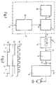
- the control device essentially comprises a variable frequency generator 2 which delivers a signal S1, the frequency of which can be adjusted by depending on the desired speed of rotation; demodulation means, such as a monostable circuit 3, which receives the signal S1 and delivers as output a control signal S2 of pre-established duration and frequency equal to that of S1, an opto-isolation member 4 being able to be inserted between the frequency generator 2 and the monostable circuit 3; and a control unit 5 of a motor 6, which controls the supply of this motor as a function of the control signal S2.
- the generator 2 comprises an oscillator 10 which delivers an output signal S0 with square wave (at the frequency of 10 MHz for example) and the output of which is connected to a programmable division operator 11 provided for dividing the frequency of the signal S0 delivered by the oscillator by the value (divider) specified at its control input 12 by a divider generator 13.
- the divider generator 13 is itself controlled by a control signal V d corresponding to the desired speed for the motor (fixed speed, for example, by an operator via a keyboard or other similar member).
- the divider generator 13 thus delivers an output signal indicating the value by which the frequency produced by the oscillator 10 must be divided (that is to say the divider) as a function of the desired speed.
- the signal S1 (see FIG.
- the frequency of S1 can vary from 0 to 20 KHz, which corresponds respectively to the absence of supply and a zero speed of the motor and to a continuous supply and the maximum speed of the motor (in the latter case the division is by 500 for example).
- the signal S1 supplied to an input 15 of the monostable circuit 3, causes the latter to deliver a sequence of pulses whose frequency is equal to the variable frequency of the signal S1 (and therefore varies from 0 to 20 KHz ) and whose duration "T" is fixed by the monostable circuit itself.
- the pre-established duration of the pulses delivered by the monostable circuit 3 is chosen to be equal to the period corresponding to the maximum frequency produced by the division operator 11, that is to say 50 sec in the above example.
- control signal S2 supplied to the input 16 of the control unit 5 has a variable duty cycle of 0 (when S1 has a zero frequency and the monostable circuit does not deliver any output pulse) to 100% (when S1 has a maximum frequency equal to 20 KHz and the monostable circuit 3 delivers a continuous output signal).
- the signal S2, of digital type can therefore be used directly for controlling motors of different types, via control unit 5.
- This unit ensures the supply of the motor 6 by connecting it to the supply V CC as long as a pulse of the control signal S2 is present at the input 16. Consequently, the higher the frequency of the control signal, the longer the motor is powered, the faster it runs. At the limit, when the duty cycle of the control signal S2 is equal to 100% (the control signal is then a single continuous pulse), the motor is supplied without interruption and runs at its maximum speed.
- control signal S2 it is possible, with the control signal S2, to directly control control units constructed differently, depending on the nature of the desired control. For example, it is possible to control motors of different types (direct current, stepping or brushless), with or without braking action and with control in the first, second or third quadran.
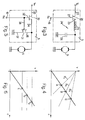
- FIG. 3 represents an exemplary embodiment of the control unit 5 in the case of a DC motor and of an actuation in the first quadrant without braking.
- the unit 5 comprises a controlled power switch 20, for example a MOSFET power transistor, having a control terminal 21 connected to the input 16 and thus receiving the control signal S2, a terminal 22 connected to the supply voltage V CC and a terminal 23 connected to an LC filter 24 comprising an inductor 25 and a capacitor 26.
- the first terminal of the inductor 25 is connected to terminal 23 of the controlled power switch 20 , and its other terminal is connected to the motor 6, while the capacitor 26 has a first terminal connected to the connection point between the inductor 25 and the motor 6, and its other terminal connected to earth, defining a reference potential line.
- FIG. 5 illustrates another embodiment of the control unit 5.
- the unit 5 controls in the first quadrant with a braking action.
- the control unit 5 of FIG. 5 comprises a first controlled power switch 30 for supply, and a second controlled power switch 31 for braking, which operates in phase opposition with respect to the switch 30.
- the switch 30, again constituted by a MOSFET power transistor, is similar to the switch 20 and therefore has a control terminal 32 connected to the input 16 which therefore receives the control signal S2, a terminal 33 connected to the supply voltage V DC and a terminal 34 connected to the motor 6 (in this case, however, no filter is not provided).
- the switch 31 also has a terminal 36 connected to the terminal 34 of the switch 30 (and to the motor 6), and another terminal 37 connected to the ground.
- the operation of the circuit in FIG. 5 is as follows: in the presence of a signal pulse S2, the switch 30 closes and connects the motor 6 to the supply voltage Vcc, as in the circuit of FIG. 3.
- the switch 31, which is in phase opposition with respect to the switch 30, is open and it plays no role.
- the switch 30 opens and isolates the motor 6 from the supply Vcc, and the switch 31 closes and connects the motor 6 to earth, which produces an effect braking.
- the opening and closing times of the switches 30 and 31 depend on the frequency (and therefore on the operating cycle) of the control signal S2, the speed of rotation of the motor is more or less high in depending on the value of this frequency.
- the signal sent to the control unit is of digital type since the coding of the desired speed is obtained by frequency modulation, the duration of the pulses being fixed (as established by monostable 3). Therefore, digital-to-analog conversion is performed only in the control unit and the control signal can pass over a transmission line without loss of coded information.
- the device according to the present invention is advantageous because of the simplicity of its circuit and because it can be used with motors of different types and can be easily adapted to various types of control, as indicated in FIGS. 3 to 6.
- an opto-insulating member 4 (required in certain applications, for safety reasons for example) can be introduced to separate the components producing the variable frequency signal S1 (part of frequency modulation comprising the frequency generator variable 2) of the part producing the control signal (demodulation part comprising the monostable circuit 3), without causing signal distortion.
- variable frequency generator can also be produced by means of other types of frequency modulators, or else that it can be constituted by a microprocessor programmed to deliver the variable frequency signal according to the desired speed supplied from outside, or according to operational needs previously programmed or defined at a given time.
- a microprocessor in the case where a microprocessor is used, it can receive as an input an additional signal corresponding to the actual speed of rotation of the motor 6, obtained for example at by means of an encoder, and compensate for possible errors in the speed of rotation, thus forming a closed-circuit adjustment system.
- the demodulation means can be of several types. For example, instead of a monostable pulse generator 3, it is possible to provide a phase locked loop (PLL circuit).
- PLL circuit phase locked loop
- the controlled power switches can also be of any type suitable for specific needs.
- the two switches can be either of the opposite type, so as to automatically operate in phase opposition, or of the same type, an inverter being able to be provided between the input 16 of the control unit 5 and one of the controlled terminals.
Landscapes
- Engineering & Computer Science (AREA)
- Power Engineering (AREA)
- Control Of Electric Motors In General (AREA)
- Control Of Direct Current Motors (AREA)
- Control Of Stepping Motors (AREA)
- Control Of Motors That Do Not Use Commutators (AREA)
- Valve Device For Special Equipments (AREA)
- Control Of Multiple Motors (AREA)
- Selective Calling Equipment (AREA)
Applications Claiming Priority (2)
| Application Number | Priority Date | Filing Date | Title |
|---|---|---|---|
| IT6745790 | 1990-06-22 | ||
| IT67457A IT1240703B (it) | 1990-06-22 | 1990-06-22 | Dispositivo di controllo della velocita' di rotazione di motori elettrici. |
Publications (2)
| Publication Number | Publication Date |
|---|---|
| EP0465381A1 EP0465381A1 (fr) | 1992-01-08 |
| EP0465381B1 true EP0465381B1 (fr) | 1995-05-03 |
Family
ID=11302541
Family Applications (1)
| Application Number | Title | Priority Date | Filing Date |
|---|---|---|---|
| EP91420200A Expired - Lifetime EP0465381B1 (fr) | 1990-06-22 | 1991-06-18 | Dispositif de commande de la vitesse de rotation de moteur électrique |
Country Status (7)
| Country | Link |
|---|---|
| US (1) | US5590237A (it) |
| EP (1) | EP0465381B1 (it) |
| JP (2) | JPH04229094A (it) |
| AT (1) | ATE122185T1 (it) |
| DE (1) | DE69109380T2 (it) |
| ES (1) | ES2071269T3 (it) |
| IT (1) | IT1240703B (it) |
Families Citing this family (3)
| Publication number | Priority date | Publication date | Assignee | Title |
|---|---|---|---|---|
| FR2706621B1 (fr) * | 1993-06-09 | 1995-08-04 | Sagem | Circuit de contrôle du courant électrique d'un moteur. |
| JP2006149141A (ja) * | 2004-11-24 | 2006-06-08 | Nippon Densan Corp | モータ駆動制御方法及びモータ駆動制御装置 |
| JP7352967B2 (ja) * | 2020-11-06 | 2023-09-29 | 株式会社メレック | 駆動装置 |
Family Cites Families (23)
| Publication number | Priority date | Publication date | Assignee | Title |
|---|---|---|---|---|
| US3678356A (en) * | 1967-09-26 | 1972-07-18 | Dynamic Precision Controls Cor | Frequency responsive electrical circuit |
| US3803473A (en) * | 1973-05-07 | 1974-04-09 | Allis Chalmers | Variable time ratio control having speed potentiometer failure protection |
| US3875486A (en) * | 1973-10-12 | 1975-04-01 | William J Barton | Motor speed control circuit |
| US4447709A (en) * | 1976-05-25 | 1984-05-08 | Olin Corporation | Method for electrically perforating dielectric webs |
| US4309645A (en) * | 1976-07-07 | 1982-01-05 | Villeneuve Dail A De | DC Motor speed controller |
| JPS5323511U (it) * | 1976-08-06 | 1978-02-28 | ||
| JPS5320521A (en) * | 1976-08-10 | 1978-02-24 | Matsushita Electric Ind Co Ltd | Motor control device |
| JPS5925998B2 (ja) * | 1976-10-29 | 1984-06-22 | 株式会社東芝 | 液体処理装置 |
| JPS5847030B2 (ja) * | 1977-03-30 | 1983-10-20 | 松下電器産業株式会社 | 回転体の回転速度表示装置 |
| US4360767A (en) * | 1979-02-09 | 1982-11-23 | Matsushita Electric Industrial Co., Ltd. | Motor speed control apparatus |
| US4280104A (en) * | 1979-08-10 | 1981-07-21 | Matsushita Electric Corporation Of America | Phase locked loop system with improved acquisition |
| CH647901A5 (de) * | 1979-10-19 | 1985-02-15 | Gegauf Fritz Ag | Elektrische antriebsvorrichtung mit einem aus dem netz ueber einen gleichrichter gespeisten gleichstrommotor. |
| DE3000403C2 (de) * | 1980-01-08 | 1986-04-03 | Danfoss A/S, Nordborg | Steuerschaltung für einen Mehrphasenverbraucher |
| SE448813B (sv) * | 1980-03-24 | 1987-03-23 | Steeper Hugh Ltd | Elmotordriven protes, speciellt handprotes |
| US4424470A (en) * | 1982-02-25 | 1984-01-03 | Finch Robert A | Motor control circuit for radio controlled models |
| JPS59117482A (ja) * | 1982-12-24 | 1984-07-06 | Nec Corp | モ−タ制御装置 |
| JPS59147532A (ja) * | 1983-02-14 | 1984-08-23 | Hitachi Ltd | 検波回路 |
| JPS6035980A (ja) * | 1983-08-04 | 1985-02-23 | Canon Inc | モ−タの制御装置 |
| JPS60255083A (ja) * | 1984-05-30 | 1985-12-16 | Toshiba Corp | モ−タ駆動装置 |
| JPS62213589A (ja) * | 1986-03-14 | 1987-09-19 | Copyer Co Ltd | ジアゾ複写機における駆動モ−タの制御方法 |
| JPS6392292A (ja) * | 1986-10-03 | 1988-04-22 | Hitachi Ltd | 直流電動機の運転制御方法 |
| JPS63234896A (ja) * | 1987-03-19 | 1988-09-30 | Sony Corp | モ−タ駆動回路 |
| DE8806823U1 (de) * | 1988-05-25 | 1988-12-08 | Bosch-Siemens Hausgeräte GmbH, 8000 München | Gleichstrommotorbetriebene Küchenmaschine |
-
1990
- 1990-06-22 IT IT67457A patent/IT1240703B/it active IP Right Grant
-
1991
- 1991-06-12 US US07/713,367 patent/US5590237A/en not_active Expired - Lifetime
- 1991-06-18 EP EP91420200A patent/EP0465381B1/fr not_active Expired - Lifetime
- 1991-06-18 ES ES91420200T patent/ES2071269T3/es not_active Expired - Lifetime
- 1991-06-18 AT AT91420200T patent/ATE122185T1/de not_active IP Right Cessation
- 1991-06-18 DE DE69109380T patent/DE69109380T2/de not_active Expired - Fee Related
- 1991-06-20 JP JP3174815A patent/JPH04229094A/ja active Pending
-
1997
- 1997-11-27 JP JP010925U patent/JPH10202U/ja active Pending
Also Published As
| Publication number | Publication date |
|---|---|
| DE69109380D1 (de) | 1995-06-08 |
| JPH04229094A (ja) | 1992-08-18 |
| EP0465381A1 (fr) | 1992-01-08 |
| IT9067457A0 (it) | 1990-06-22 |
| JPH10202U (ja) | 1998-08-25 |
| IT9067457A1 (it) | 1991-12-22 |
| DE69109380T2 (de) | 1995-11-02 |
| IT1240703B (it) | 1993-12-17 |
| ATE122185T1 (de) | 1995-05-15 |
| US5590237A (en) | 1996-12-31 |
| ES2071269T3 (es) | 1995-06-16 |
Similar Documents
| Publication | Publication Date | Title |
|---|---|---|
| FR2532490A1 (fr) | Dispositif de commande d'un moteur a courant continu sans balais | |
| FR2557753A1 (fr) | Dispositif de commande electrique et circuit d'excitation pour charge electrique | |
| FR2811824A1 (fr) | Moteur electrique a deux modes de communication d'alimentation | |
| EP0254215B1 (fr) | Dispositif d'entraînement électrique pour pièce à main chirurgicale, notamment dentaire | |
| WO2007083062A1 (fr) | Dispositif de pilotage d'une machine tournante polyphasee | |
| EP0788678A1 (fr) | Procede et dispositif de commande de puissance d'une charge via un systeme a reglage de phase | |
| EP0465381B1 (fr) | Dispositif de commande de la vitesse de rotation de moteur électrique | |
| EP0267252B1 (fr) | Convertisseur de frequence pour l'alimentation stabilisee de moteurs asynchrones | |
| EP0642144B1 (fr) | Dispositif de transmission de signaux électriques de puissance à un ensemble tournant | |
| EP0952680B1 (fr) | Transmission d'une consigne de fonctionnement par une ligne d'alimentation alternative | |
| FR2639489A1 (fr) | Dispositif interrupteur de puissance, notamment pour convertisseur de frequence | |
| EP0038264A1 (fr) | Dispositif de contrôle du freinage électrique pour moteur à courant continu | |
| FR2765746A1 (fr) | Procede et dispositif de commande de commutateurs pour regulation par modulation d'impulsions a frequence commandable | |
| FR2479590A1 (fr) | Circuit de protection a reponse rapide pour transistor de puissance, et dispositif d'alimentation electrique a decoupage comportant un tel circuit | |
| FR2881296A1 (fr) | Procede et systeme de limitation du courant en sortie d'un variateur de vitesse fonctionnant selon une loi de commande u/f | |
| FR2562737A1 (fr) | Procede et circuit de commande d'un moteur pas a pas alimente par une tension continue | |
| EP0560653B1 (fr) | Procédé de commande d'une charge électromécanique par au moins un convertisseur à commutateur(s) à impulsion et dispositif pour sa mise en oeuvre | |
| FR2662315A1 (fr) | Circuit de modulation de largeur d'impulsions. | |
| FR2496356A1 (fr) | Dispositif de commande de la vitesse d'un moteur electrique, notamment pour machine a laver le linge | |
| FR2712747A1 (fr) | Dispositif d'alimentation d'une charge résistive à partir d'une batterie de stockage d'énergie d'un véhicule. | |
| FR2503484A1 (fr) | Circuit d'amplification muni de moyens pour supprimer des sauts de tension continue a la sortie de ce circuit | |
| EP0838895B1 (fr) | Commande d'un moteur électrique pas à pas de véhicule automobile, notamment d'un moteur pas à pas pour la correction d'un projecteur | |
| FR2630274A1 (fr) | Dispositif de commande d'un moteur a courant continu en traction et freinage | |
| FR2629957A1 (fr) | Regulateur de la tension de charge d'une batterie sur la valeur crete de la tension alternateur | |
| EP0577474A1 (fr) | Circuit de sonnerie notamment pour poste téléphonique |
Legal Events
| Date | Code | Title | Description |
|---|---|---|---|
| PUAI | Public reference made under article 153(3) epc to a published international application that has entered the european phase |
Free format text: ORIGINAL CODE: 0009012 |
|
| AK | Designated contracting states |
Kind code of ref document: A1 Designated state(s): AT BE CH DE DK ES FR GB GR IT LI LU NL SE |
|
| 17P | Request for examination filed |
Effective date: 19920121 |
|
| 17Q | First examination report despatched |
Effective date: 19931013 |
|
| GRAA | (expected) grant |
Free format text: ORIGINAL CODE: 0009210 |
|
| AK | Designated contracting states |
Kind code of ref document: B1 Designated state(s): AT BE CH DE DK ES FR GB GR IT LI LU NL SE |
|
| PG25 | Lapsed in a contracting state [announced via postgrant information from national office to epo] |
Ref country code: DK Effective date: 19950503 Ref country code: GR Free format text: LAPSE BECAUSE OF FAILURE TO SUBMIT A TRANSLATION OF THE DESCRIPTION OR TO PAY THE FEE WITHIN THE PRESCRIBED TIME-LIMIT Effective date: 19950503 |
|
| REF | Corresponds to: |
Ref document number: 122185 Country of ref document: AT Date of ref document: 19950515 Kind code of ref document: T |
|
| ITF | It: translation for a ep patent filed | ||
| REF | Corresponds to: |
Ref document number: 69109380 Country of ref document: DE Date of ref document: 19950608 |
|
| GBT | Gb: translation of ep patent filed (gb section 77(6)(a)/1977) |
Effective date: 19950515 |
|
| REG | Reference to a national code |
Ref country code: ES Ref legal event code: FG2A Ref document number: 2071269 Country of ref document: ES Kind code of ref document: T3 |
|
| PG25 | Lapsed in a contracting state [announced via postgrant information from national office to epo] |
Ref country code: LU Free format text: LAPSE BECAUSE OF NON-PAYMENT OF DUE FEES Effective date: 19950630 |
|
| PG25 | Lapsed in a contracting state [announced via postgrant information from national office to epo] |
Ref country code: SE Effective date: 19950803 |
|
| PLBE | No opposition filed within time limit |
Free format text: ORIGINAL CODE: 0009261 |
|
| STAA | Information on the status of an ep patent application or granted ep patent |
Free format text: STATUS: NO OPPOSITION FILED WITHIN TIME LIMIT |
|
| 26N | No opposition filed | ||
| REG | Reference to a national code |
Ref country code: GB Ref legal event code: IF02 |
|
| PGFP | Annual fee paid to national office [announced via postgrant information from national office to epo] |
Ref country code: AT Payment date: 20040506 Year of fee payment: 14 |
|
| PGFP | Annual fee paid to national office [announced via postgrant information from national office to epo] |
Ref country code: NL Payment date: 20040510 Year of fee payment: 14 |
|
| PGFP | Annual fee paid to national office [announced via postgrant information from national office to epo] |
Ref country code: ES Payment date: 20040616 Year of fee payment: 14 |
|
| PGFP | Annual fee paid to national office [announced via postgrant information from national office to epo] |
Ref country code: BE Payment date: 20040625 Year of fee payment: 14 |
|
| REG | Reference to a national code |
Ref country code: FR Ref legal event code: CD |
|
| REG | Reference to a national code |
Ref country code: CH Ref legal event code: PFA Owner name: GAMBRO HOSPAL (SCHWEIZ) AG Free format text: HOSPAL AG#DORNACHERSTRASSE 8#4012 BASEL (CH) -TRANSFER TO- GAMBRO HOSPAL (SCHWEIZ) AG#PFLUGGAESSLEIN 2#4001 BASEL (CH) |
|
| PG25 | Lapsed in a contracting state [announced via postgrant information from national office to epo] |
Ref country code: AT Free format text: LAPSE BECAUSE OF NON-PAYMENT OF DUE FEES Effective date: 20050618 |
|
| PG25 | Lapsed in a contracting state [announced via postgrant information from national office to epo] |
Ref country code: ES Free format text: LAPSE BECAUSE OF NON-PAYMENT OF DUE FEES Effective date: 20050620 |
|
| PG25 | Lapsed in a contracting state [announced via postgrant information from national office to epo] |
Ref country code: BE Free format text: LAPSE BECAUSE OF NON-PAYMENT OF DUE FEES Effective date: 20050630 |
|
| PG25 | Lapsed in a contracting state [announced via postgrant information from national office to epo] |
Ref country code: NL Free format text: LAPSE BECAUSE OF NON-PAYMENT OF DUE FEES Effective date: 20060101 |
|
| NLV4 | Nl: lapsed or anulled due to non-payment of the annual fee |
Effective date: 20060101 |
|
| REG | Reference to a national code |
Ref country code: ES Ref legal event code: FD2A Effective date: 20050620 |
|
| REG | Reference to a national code |
Ref country code: CH Ref legal event code: PVP |
|
| REG | Reference to a national code |
Ref country code: GB Ref legal event code: 732E |
|
| BERE | Be: lapsed |
Owner name: *HOSPAL A.G. Effective date: 20050630 |
|
| PGFP | Annual fee paid to national office [announced via postgrant information from national office to epo] |
Ref country code: FR Payment date: 20090605 Year of fee payment: 19 Ref country code: IT Payment date: 20090620 Year of fee payment: 19 |
|
| PGFP | Annual fee paid to national office [announced via postgrant information from national office to epo] |
Ref country code: CH Payment date: 20090430 Year of fee payment: 19 |
|
| PGFP | Annual fee paid to national office [announced via postgrant information from national office to epo] |
Ref country code: DE Payment date: 20090630 Year of fee payment: 19 Ref country code: GB Payment date: 20090507 Year of fee payment: 19 |
|
| REG | Reference to a national code |
Ref country code: CH Ref legal event code: PL |
|
| GBPC | Gb: european patent ceased through non-payment of renewal fee |
Effective date: 20100618 |
|
| REG | Reference to a national code |
Ref country code: FR Ref legal event code: ST Effective date: 20110228 |
|
| PG25 | Lapsed in a contracting state [announced via postgrant information from national office to epo] |
Ref country code: IT Free format text: LAPSE BECAUSE OF NON-PAYMENT OF DUE FEES Effective date: 20100618 |
|
| PG25 | Lapsed in a contracting state [announced via postgrant information from national office to epo] |
Ref country code: LI Free format text: LAPSE BECAUSE OF NON-PAYMENT OF DUE FEES Effective date: 20100630 Ref country code: DE Free format text: LAPSE BECAUSE OF NON-PAYMENT OF DUE FEES Effective date: 20110101 Ref country code: CH Free format text: LAPSE BECAUSE OF NON-PAYMENT OF DUE FEES Effective date: 20100630 |
|
| PG25 | Lapsed in a contracting state [announced via postgrant information from national office to epo] |
Ref country code: FR Free format text: LAPSE BECAUSE OF NON-PAYMENT OF DUE FEES Effective date: 20100630 |
|
| PG25 | Lapsed in a contracting state [announced via postgrant information from national office to epo] |
Ref country code: GB Free format text: LAPSE BECAUSE OF NON-PAYMENT OF DUE FEES Effective date: 20100618 |