EP0465450B1 - Hydraulischer Dreh-Impuls-Erzeuger - Google Patents
Hydraulischer Dreh-Impuls-Erzeuger Download PDFInfo
- Publication number
- EP0465450B1 EP0465450B1 EP91850182A EP91850182A EP0465450B1 EP 0465450 B1 EP0465450 B1 EP 0465450B1 EP 91850182 A EP91850182 A EP 91850182A EP 91850182 A EP91850182 A EP 91850182A EP 0465450 B1 EP0465450 B1 EP 0465450B1
- Authority
- EP
- European Patent Office
- Prior art keywords
- fluid chamber
- contact element
- seal
- impulse generator
- drive member
- Prior art date
- Legal status (The legal status is an assumption and is not a legal conclusion. Google has not performed a legal analysis and makes no representation as to the accuracy of the status listed.)
- Expired - Lifetime
Links
Images

Classifications
-
- B—PERFORMING OPERATIONS; TRANSPORTING
- B25—HAND TOOLS; PORTABLE POWER-DRIVEN TOOLS; MANIPULATORS
- B25B—TOOLS OR BENCH DEVICES NOT OTHERWISE PROVIDED FOR, FOR FASTENING, CONNECTING, DISENGAGING, OR HOLDING
- B25B21/00—Portable power-driven screw or nut setting or loosening tools; Attachments for drilling apparatus serving the same purpose
- B25B21/02—Portable power-driven screw or nut setting or loosening tools; Attachments for drilling apparatus serving the same purpose with means for imparting impact to screwdriver blade or nut socket
Definitions
- This invention relates to a hydraulic torque impulse generator of the type having a drive member connected to a rotation motor and including a cylindrical fluid chamber defined by a circumferential wall and two end walls, an output spindle rotatably supported in a coaxial relationship with the drive member and having a rear portion extending into the fluid chamber, which spindle portion has at least one radial slot each supporting a radially movable seal element for sealing cooperation with seal lands on the circumferential fluid chamber wall, and first seal ridges on the rear spindle portion for sealing cooperation with second seal ridges on the circumferential fluid chamber wall, for dividing the fluid chamber into at least one high pressure compartment and at least one low pressure compartment during short intervals of the relative rotation between the drive member and the output spindle (see e.g. EP-A-290 411).
- the object of the invention is to accomplish an improved power output of a torque impulse generator of the above type by combining a good tightness of the fluid chamber compartments during the impulse generating phase and a low friction acceleration phase.
- Fig 1 shows, partly in section, a side view of a power wrench comprising a torque impulse generator according to the invention.
- Fig 2 shows, on a larger scale, a fractional section of the device in Fig 1.
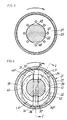
- Fig 3 shows a cross section along line III-III in Fig 1.
- Fig 4 shows a cross section along line IV-IV in Fig 1.
- the sectional part of Fig 1 illustrates a section taken along line I-I in Fig 4.
- the power wrench shown in Fig 1 is pneumatically powered and comprises a housing 10, a handle 11, a pressure air conduit connection 12 and an exhaust silencer 13 located at the lower end of the handle 11, and a throttle valve operated by a trigger 14.
- a pneumatic vane motor 16 which via a hydraulic torque impulse generator 17 is drivingly connected to an output spindle 18.
- the latter is formed with a square end 19 for connection of a nut socket.
- the impulse generator which generally is of a type prevously described in for instance E.P. Application No. 0 290 411, includes a drive member 21 drivingly coupled to the motor 16 and a rear portion 22 of the output spindle 18.
- the drive member 21 comprises a tube shaped portion 23 enclosing a cylindrical fluid chamber 24 with a circumferential wall 20 and end walls 25, 28.
- the rear end wall 25 is secured to the tube shaped portion 23 by means of a ring nut 26.
- the rear end wall 25 is formed with a rearwardly extending stub axle 27 which is drivingly coupled via a spline connection to the motor 16.
- the forward end wall 28 of the fluid chamber 24 is integral with the tube shaped portion 23.
- the rear end wall 25 is clamped by the nut 26 against a first shoulder 29 in the drive member portion 23.
- a second shoulder 30 is formed on the portion 23 to cooperate sealingly with an annular contact element 37 located inside the end wall 25.
- the contact element 37 is axially displaceable between the shoulder 30 and the end wall 25.
- the rear portion 22 of the output spindle 18 is formed with two diametrically opposite radial slots 31, 32 in which two sliding vanes 33, 34 are supported.
- the vanes 33, 34 are arranged to sealingly cooperate with two axially extending seal lands 35, 36 on the wall 20 of the fluid chamber 24.
- the spindle portion 22 is formed with a first set of two diametrically opposite seal ridges 38, 39 for sealing cooperation with a second set of two corresponding seal ridges 40, 41 on the fluid chamber wall 20. The latters are 90° circumferentially spaced from the seal lands 35, 36.
- the fluid chamber 24 is divided into two high pressure compartments H.P. and two low pressure compartments L.P. This occurs during short intervals of the relative rotation between the drive member 21 and the output spindle 18.
- valve means are provided to avoid, via bypass connections, that torque impulses are generated more than once every relative revolution between the drive member 21 and the output spindle 18.
- Such valve means could be of any previously known type and are not described in detail.
- the spindle portion 22 has annular shoulders 42 and 43 which are located substantially flush with the ends of the vanes 33, 34.
- the contact element 37 is arranged to cooperate sealingly with the shoulder 43, the rear ends of the vanes 33, 34 as well as with the shoulder 30 on the fluid chamber wall 20.
- a pressure chamber 44 between the element 37 and the end wall 25. This pressure chamber 44 communicates with the high pressure compartments H.P. of the fluid chamber 24 via axial grooves 45, 46 which extend rearwardly from the vane slots 31, 32.
- the contact element 37 comprises a flat, annular washer provided with a number of through openings 47 which are intended to facilitate fluid communication between the area between the contact element 37 itself and the shoulder 43 and the pressure chamber 44.
- the distance between the spindle shoulders 30 and 42 is somewhat larger than the length of the vanes 33, 34 to ensure that the vanes do not get jammed or cause frictional resistance in their contact with the end walls. This inevitably causes a poor sealing of the high pressure compartments. Since these problems are effectively avoided by the contact element arrangement according to the invention, the length of the vanes can be exactly equal to the distance between the shoulders 30 and 42. This means that the tightness of the high pressure compartments H.P. is considerably improved during the impulse generating phase as the contact element 37 gets a good sealing contact both with the ends of the vanes 33, 34 and the shoulders 43 and 30.
- the axially displaceable contact element 37 also ensures that there is a very low viscous friction between the ends of the vanes 33, 34 and the spindle portion 22 on one hand and the fluid chamber end walls on the other during the drive member 21 acceleration phase. As soon as the sealing contact between the vanes 33, 34 and the lands 35, 36 and between the first and second sets of seal ridges 38, 39 and 40, 41, respectively, is discontinued and the pressure peaks in the high pressure compartments H.P. have ceased, there is no longer any pressure in chamber 44 and the contact element 37 retracts automatically from its active seal position to a rear rest position.
- the clearance between the contact element 37 and the non-rotating parts, the vanes 33, 34 and the spindle portion 22, increases to a width where practically no viscous friction exists. This facilitates acceleration of the drive member 21 and results in an increased impulse rate delivered by the tool.
- the contact element arrangement is located at the rear end wall of the fluid chamber, it is to be understood that the invention is not limited to that specific design.
- the contact element arrangement according to the invention may as well be associated with the forward end wall of the fluid chamber.
Landscapes
- Engineering & Computer Science (AREA)
- Mechanical Engineering (AREA)
- Hydraulic Motors (AREA)
- Percussive Tools And Related Accessories (AREA)
- Details Of Spanners, Wrenches, And Screw Drivers And Accessories (AREA)
Claims (5)
- Hydraulischer Drehimpulserzeuger, mit einem Antriebsteil (21), der mit einem Drehmotor (16) verbunden ist und eine zylindrische Flüssigkeitskammer (24) einschließt, die durch eine umlaufende Wand (20) und zwei Stirnwände (25, 28) begrenzt ist, einer Abtriebswelle (18), die drehbar und koaxial in Bezug zu dem Antriebsteil (21) gehalten ist und einen sich in die Flüssigkeitskammer (24) erstreckenden hinteren Teil (22) aufweist, der wenigstens einen radialen Schlitz (31, 32) besitzt, der jeweils ein radial bewegliches Dichtelement (33, 34) zum abdichtenden Zusammenwirken mit Dichtleisten (35, 36) an der umlaufenden Wand (20) der Flüssigkeitskammer hält, und am hinteren Wellenteil (22) angebrachten ersten Dichtstegen (38, 39) zum abdichtenden Zusammenwirken mit zweiten Dichtstegen (40, 41) an der umlaufenden Wand (20) der Flüssigkeitskammer, wodurch die Flüssigkeitskammer (24) während kurzer Intervalle der Relativdrehung zwischen dem Antriebsteil (21) und der Antriebswelle (18) in wenigstens einen Hochdruckraum (H.P.) und wenigstens einen Niederdruckraum (L.P.) unterteilt ist, dadurch gekennzeichnet, daß einer der Stirnwände (25) der Flüssigkeitskammer ein ringförmiges, unelastisches Kontaktelement (37) zugeordnet ist, das axial frei zwischen einer Ruhe- und einer Wirkstellung verschiebbar ist, in welcher es abdichtend mit den Dichtelementen (33, 34) und dem hinteren Teil (22) der Abtriebswelle zusammenwirkt, um den Hochdruckraum (H.P.) vom Niederdruckraum (L.P.) abzudichten, zwischen dem Kontaktelement (37) und der zugeordneten Stirnwand eine Druckkammer (44) ausgebildet und eine Durchlaßöffnung (45, 46) vorhanden ist, welche die Druckkammer (44) während der erwähnten kurzen Drehintervalle verbindet mit dem Hochdruckraum (H.P.), um dadurch einen Vorlastdruck auf das Kontaktelement (37) in Richtung der Wirkstellung auszuüben.
- Impulserzeuger nach Anspruch 1, dadurch gekennzeichnet, daß das Kontaktelement (37) eine flache Form besitzt.
- Impulserzeuger nach Anspruch 1 oder 2, dadurch gekennzeichnet, daß der hintere Abtriebswellenteil (22) einen ringförmigen Absatz (43) aufweist, welcher fluchtend zu einem der Enden des Dichtelements oder der Dichtelemente (33, 34) angeordnet ist, wobei das Kontaktelement (37) in seiner Wirkstellung sowohl mit dem ringförmigen Absatz (43) als auch mit dem Ende des Dichtelements bzw. den Enden der Dichtelemente in Dichtungskontakt steht.
- Impulserzeuger nach Anspruch 3, dadurch gekennzeichnet, daß die Durchlaßöffnungen (45, 46) aus einer oder mehreren axialen Nuten im hinteren Teil der Abtriebswelle (22) bestehen, welche die Druckkammer (44) mit dem Hochdruckraum (H.P.) verbinden.
- Impulserzeuger nach Anspruch 4, dadurch gekennzeichnet, daß die axialen Nuten (45, 46) Erweiterungen der radialen Schlitze (31, 32) sind.
Applications Claiming Priority (2)
| Application Number | Priority Date | Filing Date | Title |
|---|---|---|---|
| SE9002328A SE465410B (sv) | 1990-07-03 | 1990-07-03 | Hydraulisk momentimpulsgenerator |
| SE9002328 | 1990-07-03 |
Publications (3)
| Publication Number | Publication Date |
|---|---|
| EP0465450A2 EP0465450A2 (de) | 1992-01-08 |
| EP0465450A3 EP0465450A3 (en) | 1992-10-21 |
| EP0465450B1 true EP0465450B1 (de) | 1994-08-31 |
Family
ID=20379929
Family Applications (1)
| Application Number | Title | Priority Date | Filing Date |
|---|---|---|---|
| EP91850182A Expired - Lifetime EP0465450B1 (de) | 1990-07-03 | 1991-06-28 | Hydraulischer Dreh-Impuls-Erzeuger |
Country Status (5)
| Country | Link |
|---|---|
| US (1) | US5147245A (de) |
| EP (1) | EP0465450B1 (de) |
| JP (1) | JP2955409B2 (de) |
| DE (1) | DE69103700T2 (de) |
| SE (1) | SE465410B (de) |
Families Citing this family (6)
| Publication number | Priority date | Publication date | Assignee | Title |
|---|---|---|---|---|
| US6105595A (en) * | 1997-03-07 | 2000-08-22 | Cooper Technologies Co. | Method, system, and apparatus for automatically preventing or allowing flow of a fluid |
| US5890848A (en) * | 1997-08-05 | 1999-04-06 | Cooper Technologies Company | Method and apparatus for simultaneously lubricating a cutting point of a tool and controlling the application rate of the tool to a work piece |
| JP3615125B2 (ja) * | 2000-03-30 | 2005-01-26 | 株式会社マキタ | オイルユニット及び電動工具 |
| JP3361794B2 (ja) * | 2000-08-11 | 2003-01-07 | 瓜生製作株式会社 | 油圧式トルクレンチの打撃トルク発生装置 |
| JP2007526806A (ja) * | 2004-02-11 | 2007-09-20 | ザ プロクター アンド ギャンブル カンパニー | 疎水性表面コーティングされた吸収性物品 |
| ES2365404T3 (es) | 2006-11-13 | 2011-10-04 | COOPER POWER TOOLS GMBH & CO. | Herramienta de impulso y placa delantera correspondiente. |
Family Cites Families (3)
| Publication number | Priority date | Publication date | Assignee | Title |
|---|---|---|---|---|
| JPS6327266U (de) * | 1986-07-30 | 1988-02-23 | ||
| SE451437B (sv) * | 1986-10-03 | 1987-10-12 | Atlas Copco Ab | Hydraulisk momentimpulsgenerator |
| SE467487B (sv) * | 1987-05-08 | 1992-07-27 | Atlas Copco Ab | Hydraulisk momentimpulsgenerator |
-
1990
- 1990-07-03 SE SE9002328A patent/SE465410B/sv not_active IP Right Cessation
-
1991
- 1991-06-28 DE DE69103700T patent/DE69103700T2/de not_active Expired - Fee Related
- 1991-06-28 EP EP91850182A patent/EP0465450B1/de not_active Expired - Lifetime
- 1991-06-28 US US07/722,693 patent/US5147245A/en not_active Expired - Lifetime
- 1991-07-03 JP JP3258257A patent/JP2955409B2/ja not_active Expired - Fee Related
Also Published As
| Publication number | Publication date |
|---|---|
| JP2955409B2 (ja) | 1999-10-04 |
| JPH06238573A (ja) | 1994-08-30 |
| DE69103700D1 (de) | 1994-10-06 |
| EP0465450A3 (en) | 1992-10-21 |
| SE9002328D0 (sv) | 1990-07-03 |
| SE465410B (sv) | 1991-09-09 |
| EP0465450A2 (de) | 1992-01-08 |
| DE69103700T2 (de) | 1995-05-04 |
| SE9002328L (de) | 1991-09-09 |
| US5147245A (en) | 1992-09-15 |
Similar Documents
| Publication | Publication Date | Title |
|---|---|---|
| EP0267169B1 (de) | Hydraulischer Drehmoment-Impuls-Erzeuger | |
| EP0465450B1 (de) | Hydraulischer Dreh-Impuls-Erzeuger | |
| US4884995A (en) | Hydraulic torque impulse generator | |
| SE469419B (sv) | Motordrivet momentimpulsverktyg | |
| SE441989B (sv) | Pneumatisk mutterdragare for tva hastigheter | |
| US4140446A (en) | Rotary pneumatic tool with vibration absorbing means | |
| US2947283A (en) | Impact tool | |
| EP0243334B1 (de) | Hydraulischer Drehmomentimpuls-Erzeuger mit Bypass-Vorrichtung | |
| SE525316C2 (sv) | Pneumatiskt motordrivet verktyg med axiellt eller radiellt utblås | |
| EP0235102B1 (de) | Hydraulischer Drehmomentimpulserzeuger | |
| EP1266126B1 (de) | Reversierbar-zweikammer-druckluftmotor | |
| EP0569344B1 (de) | Hydraulischer Drehimpuls-Erzeuger | |
| WO1998026903A1 (en) | Torque impulse tool with automatic power shut-off comprising two inertia bodies | |
| CA2614994C (en) | Rotary tool | |
| SE429309B (sv) | Verktygsmaskin for halbearbetning | |
| EP0254699B1 (de) | Hydraulischer Drehmoment-Impuls-Erzeuger | |
| EP0665087B1 (de) | Hydraulischer Drehmomentimpuls-Erzeuger | |
| US3498186A (en) | Multiple lobed chamber air motor | |
| JPS61109667A (ja) | ボルト締付機 | |
| JPS5932268B2 (ja) | 圧縮空気式打撃スクリユドライバ | |
| JPH032634B2 (de) | ||
| JPH05180247A (ja) | 駆動力伝達装置 |
Legal Events
| Date | Code | Title | Description |
|---|---|---|---|
| PUAI | Public reference made under article 153(3) epc to a published international application that has entered the european phase |
Free format text: ORIGINAL CODE: 0009012 |
|
| AK | Designated contracting states |
Kind code of ref document: A2 Designated state(s): DE FR GB IT SE |
|
| PUAL | Search report despatched |
Free format text: ORIGINAL CODE: 0009013 |
|
| AK | Designated contracting states |
Kind code of ref document: A3 Designated state(s): DE FR GB IT SE |
|
| 17P | Request for examination filed |
Effective date: 19930416 |
|
| 17Q | First examination report despatched |
Effective date: 19930831 |
|
| GRAA | (expected) grant |
Free format text: ORIGINAL CODE: 0009210 |
|
| AK | Designated contracting states |
Kind code of ref document: B1 Designated state(s): DE FR GB IT SE |
|
| REF | Corresponds to: |
Ref document number: 69103700 Country of ref document: DE Date of ref document: 19941006 |
|
| ITF | It: translation for a ep patent filed | ||
| ET | Fr: translation filed | ||
| PG25 | Lapsed in a contracting state [announced via postgrant information from national office to epo] |
Ref country code: SE Effective date: 19941130 |
|
| PLBE | No opposition filed within time limit |
Free format text: ORIGINAL CODE: 0009261 |
|
| STAA | Information on the status of an ep patent application or granted ep patent |
Free format text: STATUS: NO OPPOSITION FILED WITHIN TIME LIMIT |
|
| 26N | No opposition filed | ||
| REG | Reference to a national code |
Ref country code: GB Ref legal event code: IF02 |
|
| PGFP | Annual fee paid to national office [announced via postgrant information from national office to epo] |
Ref country code: IT Payment date: 20080625 Year of fee payment: 18 |
|
| PGFP | Annual fee paid to national office [announced via postgrant information from national office to epo] |
Ref country code: DE Payment date: 20080703 Year of fee payment: 18 |
|
| PGFP | Annual fee paid to national office [announced via postgrant information from national office to epo] |
Ref country code: FR Payment date: 20080617 Year of fee payment: 18 |
|
| PGFP | Annual fee paid to national office [announced via postgrant information from national office to epo] |
Ref country code: GB Payment date: 20080702 Year of fee payment: 18 |
|
| GBPC | Gb: european patent ceased through non-payment of renewal fee |
Effective date: 20090628 |
|
| REG | Reference to a national code |
Ref country code: FR Ref legal event code: ST Effective date: 20100226 |
|
| PG25 | Lapsed in a contracting state [announced via postgrant information from national office to epo] |
Ref country code: FR Free format text: LAPSE BECAUSE OF NON-PAYMENT OF DUE FEES Effective date: 20090630 |
|
| PG25 | Lapsed in a contracting state [announced via postgrant information from national office to epo] |
Ref country code: GB Free format text: LAPSE BECAUSE OF NON-PAYMENT OF DUE FEES Effective date: 20090628 |
|
| PG25 | Lapsed in a contracting state [announced via postgrant information from national office to epo] |
Ref country code: DE Free format text: LAPSE BECAUSE OF NON-PAYMENT OF DUE FEES Effective date: 20100101 |
|
| PG25 | Lapsed in a contracting state [announced via postgrant information from national office to epo] |
Ref country code: IT Free format text: LAPSE BECAUSE OF NON-PAYMENT OF DUE FEES Effective date: 20090628 |