EP0465660A1 - Procede de moulage par extrusion - Google Patents
Procede de moulage par extrusion Download PDFInfo
- Publication number
- EP0465660A1 EP0465660A1 EP91902754A EP91902754A EP0465660A1 EP 0465660 A1 EP0465660 A1 EP 0465660A1 EP 91902754 A EP91902754 A EP 91902754A EP 91902754 A EP91902754 A EP 91902754A EP 0465660 A1 EP0465660 A1 EP 0465660A1
- Authority
- EP
- European Patent Office
- Prior art keywords
- die
- extrusion
- molding
- extrusion orifice
- vibrations
- Prior art date
- Legal status (The legal status is an assumption and is not a legal conclusion. Google has not performed a legal analysis and makes no representation as to the accuracy of the status listed.)
- Withdrawn
Links
Images



Classifications
-
- B—PERFORMING OPERATIONS; TRANSPORTING
- B29—WORKING OF PLASTICS; WORKING OF SUBSTANCES IN A PLASTIC STATE IN GENERAL
- B29C—SHAPING OR JOINING OF PLASTICS; SHAPING OF MATERIAL IN A PLASTIC STATE, NOT OTHERWISE PROVIDED FOR; AFTER-TREATMENT OF THE SHAPED PRODUCTS, e.g. REPAIRING
- B29C48/00—Extrusion moulding, i.e. expressing the moulding material through a die or nozzle which imparts the desired form; Apparatus therefor
- B29C48/25—Component parts, details or accessories; Auxiliary operations
- B29C48/30—Extrusion nozzles or dies
- B29C48/32—Extrusion nozzles or dies with annular openings, e.g. for forming tubular articles
- B29C48/325—Extrusion nozzles or dies with annular openings, e.g. for forming tubular articles being adjustable, i.e. having adjustable exit sections
-
- B—PERFORMING OPERATIONS; TRANSPORTING
- B29—WORKING OF PLASTICS; WORKING OF SUBSTANCES IN A PLASTIC STATE IN GENERAL
- B29C—SHAPING OR JOINING OF PLASTICS; SHAPING OF MATERIAL IN A PLASTIC STATE, NOT OTHERWISE PROVIDED FOR; AFTER-TREATMENT OF THE SHAPED PRODUCTS, e.g. REPAIRING
- B29C48/00—Extrusion moulding, i.e. expressing the moulding material through a die or nozzle which imparts the desired form; Apparatus therefor
- B29C48/03—Extrusion moulding, i.e. expressing the moulding material through a die or nozzle which imparts the desired form; Apparatus therefor characterised by the shape of the extruded material at extrusion
- B29C48/07—Flat, e.g. panels
- B29C48/08—Flat, e.g. panels flexible, e.g. films
-
- B—PERFORMING OPERATIONS; TRANSPORTING
- B29—WORKING OF PLASTICS; WORKING OF SUBSTANCES IN A PLASTIC STATE IN GENERAL
- B29C—SHAPING OR JOINING OF PLASTICS; SHAPING OF MATERIAL IN A PLASTIC STATE, NOT OTHERWISE PROVIDED FOR; AFTER-TREATMENT OF THE SHAPED PRODUCTS, e.g. REPAIRING
- B29C48/00—Extrusion moulding, i.e. expressing the moulding material through a die or nozzle which imparts the desired form; Apparatus therefor
- B29C48/03—Extrusion moulding, i.e. expressing the moulding material through a die or nozzle which imparts the desired form; Apparatus therefor characterised by the shape of the extruded material at extrusion
- B29C48/09—Articles with cross-sections having partially or fully enclosed cavities, e.g. pipes or channels
- B29C48/10—Articles with cross-sections having partially or fully enclosed cavities, e.g. pipes or channels flexible, e.g. blown foils
-
- B—PERFORMING OPERATIONS; TRANSPORTING
- B29—WORKING OF PLASTICS; WORKING OF SUBSTANCES IN A PLASTIC STATE IN GENERAL
- B29C—SHAPING OR JOINING OF PLASTICS; SHAPING OF MATERIAL IN A PLASTIC STATE, NOT OTHERWISE PROVIDED FOR; AFTER-TREATMENT OF THE SHAPED PRODUCTS, e.g. REPAIRING
- B29C48/00—Extrusion moulding, i.e. expressing the moulding material through a die or nozzle which imparts the desired form; Apparatus therefor
- B29C48/14—Extrusion moulding, i.e. expressing the moulding material through a die or nozzle which imparts the desired form; Apparatus therefor characterised by the particular extruding conditions, e.g. in a modified atmosphere or by using vibration
-
- B—PERFORMING OPERATIONS; TRANSPORTING
- B29—WORKING OF PLASTICS; WORKING OF SUBSTANCES IN A PLASTIC STATE IN GENERAL
- B29C—SHAPING OR JOINING OF PLASTICS; SHAPING OF MATERIAL IN A PLASTIC STATE, NOT OTHERWISE PROVIDED FOR; AFTER-TREATMENT OF THE SHAPED PRODUCTS, e.g. REPAIRING
- B29C48/00—Extrusion moulding, i.e. expressing the moulding material through a die or nozzle which imparts the desired form; Apparatus therefor
- B29C48/25—Component parts, details or accessories; Auxiliary operations
- B29C48/30—Extrusion nozzles or dies
- B29C48/305—Extrusion nozzles or dies having a wide opening, e.g. for forming sheets
- B29C48/31—Extrusion nozzles or dies having a wide opening, e.g. for forming sheets being adjustable, i.e. having adjustable exit sections
- B29C48/313—Extrusion nozzles or dies having a wide opening, e.g. for forming sheets being adjustable, i.e. having adjustable exit sections by positioning the die lips
-
- B—PERFORMING OPERATIONS; TRANSPORTING
- B29—WORKING OF PLASTICS; WORKING OF SUBSTANCES IN A PLASTIC STATE IN GENERAL
- B29C—SHAPING OR JOINING OF PLASTICS; SHAPING OF MATERIAL IN A PLASTIC STATE, NOT OTHERWISE PROVIDED FOR; AFTER-TREATMENT OF THE SHAPED PRODUCTS, e.g. REPAIRING
- B29C48/00—Extrusion moulding, i.e. expressing the moulding material through a die or nozzle which imparts the desired form; Apparatus therefor
- B29C48/25—Component parts, details or accessories; Auxiliary operations
- B29C48/30—Extrusion nozzles or dies
- B29C48/32—Extrusion nozzles or dies with annular openings, e.g. for forming tubular articles
Definitions
- This invention relates to extrusion molding of a molding material. More particularly, it relates to an extrusion molding method whereby the fluidity of the material within the die and at an extrusion orifice may be improved for improving the productivity of molded articles, and an apparatus for carrying out the extrusion molding method.
- the JP Patent Laid-Open Patent Publication No. 57-51441 (1982) discloses a method wherein the molding material is fluidized while mechanical vibrations are applied to a die of an extrusion molding machine for improving the fluidity of the molding material so as to increase the rate of extrusion.
- vibrations are forcedly applied to a die simply secured to the extrusion molding machine, vibrations may not be transmitted in effect, and hence no satisfactory results have been obtained.
- the present invention provides a solution to this problem. It is an object of the present invention to provide a method for extrusion molding according to which a die having extrusion orifice gap adjustment means annexed thereto is set into resonant vibrations for improving the fluidity of the molding material in a die as well as productivity of the molded article of a uniform thickness, and an apparatus capable of carrying out the method smoothly and having an unforced constructional disposition.
- the extrusion molding method according to claim 1 resides in a molding method wherein molding is carried out while a die having extrusion orifice gap adjustment means annexed thereto is driven into resonant vibrations.
- the extrusion molding method according to claim 2 resides in a method in which, for improving the state of flowing of the molding material in the vicinity of the extrusion orifice of the die where in general the molding material can flow most difficultly, molding is carried out while a part of the die constituting the extrusion orifice and having the extrusion orifice gap adjustment means annexed thereto is set into resonant vibrations.
- the extrusion orifice of the die is provided at a position in register with the loop of the resonant vibrations, that is at a position of the maximum effect of the vibrations, and the frictional resistance between the molding material and the die surface in the vicinity of the extrusion orifice is reduced when carrying out molding.
- the die holder and the inlet of the molding material into the die are set so as to be in register with the nodes of the resonant vibrations when carrying out molding.
- extrusion orifice gap adjustment means is annexed to the die and at least one vibration generator is provided for setting the die into resonant vibrations.
- the resonant frequency of the extrusion orifice gap adjustment means is selected to be equal to that of the die.
- extrusion orifice gap adjustment means is annexed at a node of the resonant vibrations.
- only a part of the die in which the extrusion orifice gap adjustment means is annexed and which constitutes the extrusion orifice is set into resonant vibrations by at least one vibration generator.
- the extrusion orifice gap adjustment means represent means for performing fine adjustment of the extrusion orifice to a desired gap value.
- Fig. 1 is a side elevation, shown partly in section, showing a first embodiment of an extrusion molding apparatus according to the present invention
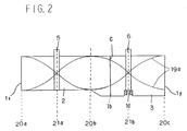
- Fig. 2 is an illustrative view showing the wavelength and the displacement waveform when a die of the extrusion molding apparatus shown in Fig. 1 is excited into 1 wavelength resonant vibrations
- fig. 3 is an illustrative view showing the wavelength and the displacement waveform when a die of the extrusion molding apparatus shown in Fig. 1 is excited into n-wavelength resonant vibrations
- Fig. 4 is a side elevation, shown partly in section, showing a second embodiment of the extrusion molding apparatus according to the present invention
- Fig. 1 is a side elevation, shown partly in section, showing a first embodiment of an extrusion molding apparatus according to the present invention
- Fig. 2 is an illustrative view showing the wavelength and the displacement waveform when a die of the extrusion molding apparatus shown in Fig. 1 is excited into 1 wavelength resonant vibrations
- Fig. 5 is an illustrative view showing the wavelength and the displacement waveform when a die in the extrusion molding apparatus shown in Fig. 4 is excited into resonant vibrations
- Fig. 6 is a side elevation, shown partially in section, showing a third embodiment of the extrusion molding apparatus according to the present invention
- Fig. 7 is an illustrative view showing the wavelength and the displacement waveform when a die of the extrusion molding apparatus shown in Fig. 6 is excited into resonant vibrations
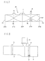
- Fig. 8 is a diagrammatic view showing an apparatus employing an ultrasonic vibrator and not encompassed by the present invention.
- Fig. 1 is a side elevation, shown partly in section, showing a first embodiment of an extrusion molding apparatus according to the present invention
- Fig. 2 is a diagram showing a displacement waveform 19a during resonant vibrations of the apparatus.
- the displacement waveform 19a of Fig. 2 is not indicative of the actual amplitude of vibrations.
- 1 is a die partitioned into a first die member 2 and a second die member 3.
- the die 1 has two opposite sides 1x and 1y which are disposed on the left side of the first die member 2 and on the right side of the second die member 3.
- An extrusion orifice 1b is formed on a contact surface of the first die member 2 contacting with the second die member 3.
- a movable member 1c as extrusion orifice gap adjustment means and a gap adjustment bolt 1d for interconnecting the movable member 1c and the second die member 3 and for moving the movable member 1c.
- the movable member 1c and the gap adjustment bolt 1d are preferably so mounted as to contact with the second die member 3 kept in resonant vibrations therewith with a large contact area.
- the movable member 1c and the gap adjustment bolt 1d are adapted for being oscillated in resonance at the same resonance frequency as that of the die 1. In this manner, the die may be oscillated in resonance without disturbances of resonance even though the extrusion orifice adjustment means are annexed to the die.
- the movable member 1c may be rendered movable by the gap adjustment bolt 1d
- the bolt 1d is threaded in its entirety so that the pitch of threads cut in a first bolt part screwed into the movable member 1c is slightly different from that of threads cut in a second bolt part screwed into the second die member 3, the bolt 1d is machined to a hexagonal outer contour at a position corresponding to a node of the resonant vibrations, and the corresponding portion of the second die member 3 is cut off to form a notch so that the gap adjustment bolt 1d may be rotated along the thereat during molding.
- the die 1 may be formed of metallic materials customarily employed for extrusion, or of various other materials, such as ceramics or graphite. Of these, the materials which will undergo only limited losses in the transmission of vibrations at the molding temperature, above all, duralmin, titanium alloys, K-monel, phosphor bronze or graphite, are most preferred.
- the first die member 2 and the second die member 3, partitioned as described above, are contacted with each other on a contact surface C with a surface contact to the maximum extent possible so that the vibrations may be transmitted most efficiently.
- the die 1 may also not be partitioned, that is, remain unitary, or be partitioned into three or more members. When the die is constituted by plural members, these members may be formed of homogeneous materials or heterogeneous materials.
- the die 1 may also be plated or coated with Teflon or titanium nitride to improve its abrasion or corrosion resistance or to lower its friction coefficient with respect to the molding material.
- a far infrared type heater capable of heating the die 1 even without contact with the die.
- the heater is contacted only with a non-oscillating portion of the die 1 kept in resonant vibrations, that is at a node of resonance where the displacement waveforms intersect each other (for example, at 21a or 21b).
- the die 1 and the far infrared heater are secured to each other at the node with the aid of, for example, a set screw.
- An air inlet attached to a die for inflation molding or an inert gas inlet attached to a variety of dies for expansion extrusion molding may also be provided at the node of resonance, as in the method of securing the heater as mentioned above.
- the inlet components are preferably formed of a material which may be subjected to fatigue due to vibrations to a lesser extent, such as titanium alloy.
- nozzle 4 is a nozzle of an extruder, such as a single-screw or a multi-screw extruder, not shown.
- the molding material is supplied from the nozzle 4 to the die 1 by way of an entrance 1a so as to be ultimately extruded at an extrusion orifice 1b by way an entrance 2a.
- the nozzle 4 is secured to the second die member 3 by securing means, such as screw, at a position substantially corresponding to the node of resonance of the second die member 3. In this manner, the vibrations imparted to the die 1 may hardly be transmitted to the nozzle 4.
- a cushioning member formed by, for example, fibers of titanium alloys, may be provided at a point of contact between the nozzle 4 and the second die member 3 for preventing the vibrations from being transmitted to the nozzle 4.
- the direction of extrusion of the molding material by means of the extrusion orifice 1b of the die 1 and the direction of vibrations transmitted to the extrusion orifice may be selected arbitrarily, it is preferred that the extruding direction be orthogonal to the vibrating direction, in order to prevent the surface temperature of the extruded material from increasing owing to the ultrasonic waves and to raise the critical extrusion speed corresponding to the initiation of melt fracture.
- the effect of the vibrations at the extrusion orifice 1b may be augmented or diminished by changing the shape of the extrusion orifice 1b.
- flanges 5 and 6 are flanges provided on the first die member 2 and the second die member 3, respectively, as die holding members. These flanges are provided at points of nodes of resonance of the first die member 2 and the second die member 3 (points 21a and 21b). It is preferred that the flanges 5 and 6 be as thin in thickness as possible to prevent the vibrations of the die 1 from being transmitted to outside and to reduces the losses of vibrations which might otherwise be caused at the flanges.
- the bolt 7 is a bolt uniformly tightening the first die member 2 and the second die member 3 by the intermediary of the flanges 5 and 6. It is preferred that the bolt 7 be not in contact with the die 1 in order to prevent the vibrations from being transmitted from the die 1 to outside.
- a tapped hole may be provided in the die 1 and a bolt introduced into the tapped hole for tightening in a known manner.
- the contact point between the bolt and the die sections be in the vicinity of the node of resonance, and that the die and the bolt be contacted with as small a contact area as possible.
- the contact point between the ultrasonic vibrator 8 and the die 1 be in register with a portion of the die 1 oscillating with the maximum amplitude, that is, an loop of resonance (such as a point 20a) at which that displacement waveforms are removed from each other to the maximum extent.
- an loop of resonance such as a point 20a
- Other loop of resonance are shown for example at points 20b and 20c.
- any of the vibration apparatus such as electric type, hydraulic type or ultrasonic type, having the frequency of vibrations in the range of 10Hz to 10MHz, may be used as the vibration apparatus for producing the resonant vibrations of the die 1.
- the ultrasonic wave vibration apparatus is most preferred because a higher energy efficiency may thereby be achieved.
- a vibration transmitter may be incorporated between the die 1 and the ultrasonic vibrator 8 as an aid or vehicle for transmitting the vibrations.
- the amplitude of the vibrations generated by the ultrasonic vibrator 8 may be easily increased or decreased in desired manner.
- the number of the vibration generator or transmitter connected to the die 1 There is no specific limitation to the number of the vibration generator or transmitter connected to the die 1. However, when a plurality of the vibration generators or transmitters are connected to the die 1, it is necessary to adjust the time of vibrations to prevent the state of resonance of the die 1 from being disturbed. The larger the number of the vibration generators connected to the die 1, the more extensive is the vibration afforded to the die.
- the resonant frequency of the die 1 is present at the time of design and manufacture to a frequency that may be followed by the ultrasonic oscillator 10, so that slight changes in the resonant frequency caused by temporal changes in the load or temperature since the time of delivery of the molding material from the nozzle 4 of the extruder to the die 1 until the time of exiting of the molding material at the extrusion orifice 1b may perpetually be coped with, while the electric power may be supplied in a required amount (less than the maximum output) to meet instantaneous changes in power demand.
- an automatic frequency follow-up system and an automatic power control system have been adopted to allow to maintain the state of resonant vibrations.
- Such system is disclosed in, for example, the JP Patent Laid-Open Publication 49-59627 (1974).
- the direction of transmission of the vibrations in the vicinity of the extrusion orifice is orthogonal to the extruding direction of the molding material.
- the die 1 may be provided with a mechanism for modifying the direction of vibrations of the die 1.
- converters such as L-L, L-R or L-L-R converters, customarily employed for ultrasonic vibrations, may be provided in the die.
- Fig. 4 shows an extrusion molding apparatus according to a second embodiment of the present invention wherein the direction of transmission of the vibrations in the vicinity of the extrusion orifice is selected to be the same as the extruding direction of the molding material.
- resonant vibrations may be performed with displacement waveforms shown in Fig. 5.
- the die 1 shown in Fig. 4 is provided with a mechanism for converting the direction of the vibrations known as the L-L converter.
- vibrations may also be transmitted at the converter in a direction deviated 90° with respect to the direction of transmission of the vibrations (Fig. 5).
- the ultrasonic vibrator 8 is coupled to the die 1 by means of a vibration transmitter 11.
- the displacement waveform is shown at 19c, when the vibration transmitter 11 is in resonant vibrations by the vibrations generated by the ultrasonic vibrator 8.
- the displacement waveform is shown at 19d and 19e, when the die L is in resonant vibrations.
- a mandrel (die member) 5 is designed in advance so as to have the same resonant frequency as that of the die member 2, and is coupled to the die member 2 by a set screw. Although there is no specific limitation to the coupling position between the die member 2 and the mandrel 3, it is preferred that, for efficiently transmitting the vibrations of the die member 2 to the mandrel 3, the connecting surfaces therebetween be at the loop of the resonance of the die member 2.
- the coupling surface between the mandrel 3 and the die member 2 may be disposed in the vicinity of the node of resonance of the die member 2, while the mandrel 3 may be contacted with the die member at other than the screw portion at a position as close to the loop of resonance of the die member 2.
- the gap adjustment bolt 1d for the extrusion orifice as extrusion orifice gap adjustment means is preferably mounted at a point of a node of resonance of the die member 2 and the mandrel 3 for preventing vibrations from being transmitted to the gap adjustment bolt 1d.
- the die may be set into resonant oscillations, because the state of resonance is not disturbed even when the gap adjustment bolt 1d is mounted on the die.
- Fine adjustment of the gap of the extrusion orifice may be achieved by adjusting the gap between the die 1 and the mandrel 3 by tightening plural gap adjustment bolts 1d provided in the die 1.
- 12 is an air supply duct, 13 an air cooling ring, 14 a cylindrical tube, 15 a stabilization plate, 16 a pair of pinch rolls. 17 a guide roll and 18 a take-up device for a molded product.
- Fig. 6 shows an extrusion apparatus according to a third embodiment, wherein a die 1 is partitioned into die members 2a, 3a and die members 2b, 3b. Ultrasonic vibrations are imparted to the die members 2b, 3b constituting the vicinity of the extrusion orifice for setting these die sections into resonant vibrations. Die holders 5, 6 are provided at node of resonance of the die members 2b, 3b to prevent the vibrations from being transmitted to the die members 2a, 3a constituting the main body of the die.
- An extrusion orifice 1b is provided at a contact surface of the die member 2b with the die member 3b and the die members 2a, 3a are contacted with the die members 2b, 3b in the vicinity thereof to prevent the molding material from being leaked at a gap otherwise formed thereat.
- the ultrasonic vibrator 8 produces longitudinal vibrations.
- the extrusion orifice 1b is positioned at an loop of resonance so that the vibrations of the die members 2b, 3b are not transmitted to the die members 2a, 3a in the vicinity of the extrusion orifice.
- the die members 2b, 3b constitute a part 2c of the die.
- the die part 2c has opposite sides 2x and 2y which are the left side of the die member 2b and the right side of the die member 3b, respectively.
- a movable member 1c and a gap adjustment bolt 1d functioning as extrusion orifice gap adjustment means, are provided in the extrusion orifice 1b, as in the embodiment shown in Fig. 1.
- the movable member 1c and the gap adjustment bolt 1d are contoured and sized so as to be vibrated in resonance at the same resonant frequency as that of the die members 2b and 3b (Fig. 7).
- 19f is a displacement waveform when the die members 2b, 3b and 1c, 1d are vibrated in resonance at the same resonant frequency.
- 20e, 20f and 20g are the loop of resonance, while 21d and 21e are the nodes of resonance.
- conventional dies may be used as die members 2a and 3a, so that die designing and production may be advantageously simplified to a larger extent. Since it is a portion of the die that is vibrated in resonance, the energy necessary for resonant vibrations may advantageously be reduced.
- the gap adjustment bolt 1d and the movable member 1c are first operated for performing fine adjustment of the gap of the extrusion orifice 1b of the die 1.
- the thickness of the extruded material such as the film or sheet, may be improved in accuracy to enable the film or sheet to be produced with a uniform thickness.
- gap adjustment of the extrusion orifice 1b may be made even during the extrusion molding operation.
- the nozzle 4 of the molding machine is then connected to the die member 3 and the molding material is supplied to the die 1 to perform extrusion molding.
- the ultrasonic vibrator 8 is caused to produce ultrasonic vibrations by ultrasonic oscillator 10 for setting the die 1 into n-wavelength resonant oscillations (Figs. 2 and 3).
- vibrations are produced so that, between the surface 1x of the die 1 connected to the vibrator 8 and the opposite surface 1y, the number of loop and the number of nodes of the standing wave generated during resonant vibrations are equal to 2n+1 and 2n, respectively.
- 19b is a displacement waveform.
- One of the loop is 20d and one of the nodes is 21c.
- n is preferably less than 3.
- the oscillation frequency may be selected arbitrarily, it is preferred that, in order for the vibrations to act most effectively on the fluidized material, the oscillation frequency be in the range from 10 to 100 kHz.
- the mode of vibrations may be any of well-known modes, such as transverse, torsional, radial or bended vibrations, in addition to the longitudinal vibrations.
- the amplitudes of the ultrasonic vibrations afforded to the die 1 may be 0.1 to 100 ⁇ m for effectively improving the fluidity of the molding material.
- the molding material moldable in accordance with the above described extrusion molding method and apparatus may be such material as will exhibit at least certain fluidity during molding, such as, for example, organic materials such as thermoplastic resins, thermosetting resins, rubber or elastomer, inorganic materials such as inorganic polymer materials, ceramics, metal or glass, other foodstuff or mixtures thereof.
- organic materials such as thermoplastic resins, thermosetting resins, rubber or elastomer
- inorganic materials such as inorganic polymer materials, ceramics, metal or glass, other foodstuff or mixtures thereof.
- the thermoplastic resins include ⁇ -olefinic resins, such as polyethylene, polypropylene, polystyrene, syndiotactic polystyrene, vinyl chloride resin, polybutene, ultra high molecular weight polyethylene, polymethyl pentene, ionomer resin or polybutylene; polyester resins, such as polyethylene terephthalate, polybutylene terephthalate or polyallylate; polyether resins, such as polysulfone, polyether sulfone, polyether ketone, polyether ether ketone, polyallyl sulfone, polyoxybenzylene, polyphenylene oxide or polycyanoallyl ether (JP Patent Laid-Open Publication No.
- ⁇ -olefinic resins such as polyethylene, polypropylene, polystyrene, syndiotactic polystyrene, vinyl chloride resin, polybutene, ultra high molecular weight polyethylene, polymethyl pentene
- polycarbonate resin polyimide resin; polyamide resin; polyamide imide resin; methacrylic resin; fluorine resin; methacrylate-butadiene-styrene (MBS) resin; acrylate-acrylonitrile-styrene (AAS) resin; acrylonitrile-styrene (AS) resin; chlorinated acrylonitrile-polyethylene-styrene (ACS) resin; acrylonitrile-butadiene-styrene (ABS) resin; polyacetal resin; cellulose resin; polyvinylidene chloride; chlorinated polyethylene; ethylene-vinyl acetate (EVA) resin; polyurethane resin; silicone resin; allylic resin; furan resin; or liquid crystalline polymer.
- EVA acrylonitrile-polyethylene-styrene
- thermosetting resins include epoxy resin, phenolic resin, polybutadiene resin, silicone resin, unsaturated polyester resin or amino resin.
- thermoplastic elastomers include styrene-butadiene elastomer, polyester elastomer, polyethylene elastomer, urethane elastomer and vinyl chloride elastomer.
- the extrusion molding method according to the present invention means any molding methods in which the molding material in the fluidized state travels through a die so as to be extruded into a predetermined shape, such as inflation molding, sheet molding, round-bar molding, pipe molding, profiled extrusion molding, multi-layer co-extrusion molding, filament molding, blow molding, wire coating or extrusion foam molding.
- a film of a higher strength may be produced by inflation molding in accordance with the present invention.
- the die temperature, extrusion quantity and the blow-up ratio may be determined as a function of the feed material and the ultimate molded product, the die temperature of (Tm) +20°C to (Tm) +130°C, above all, (Tm) +20°C to (Tm) +35°C, Tm being the melting temperature of the feed material, and the blow-up ratio of 1 to 5, are preferred.
- Extrusion molding was carried out under the above conditions, while the die was kept in the state of resonant vibrations, and the state of occurrence of melt fracture at this time was checked.
- the pressure within the nozzle which is a measure of the fluid flow resistance of the molding material occurring in the passage from the nozzle to the die exit orifice, was measured for the rate of extrusion of 4 Kg/hr. Further, when the rate of extrusion was set to 10,40 and 80 Kg/hr, sheets adjusted for thickness by five gap adjustment bolts were taken up and samples each 100 mm in width from the sheet center towards both sides were cut to check for thickness fluctuation coefficients along the sheet width.
- the height position of the cooling ring was set to a value at which the valve was stabilized.
- Comparative Example 3 The procedure of Comparative Example 3 was followed, except raising the die temperature gradually, in order to search for a temperature at which a satisfactory film can be produced by molding. It was found that a film having a satisfactory appearance can be obtained at 260°C.
- the impact strength and the degree of haze were measured of the film.
- the fluidity of the molding material, especially the material with low fluidity, within the die may be improved, as a result of which the occurrences of melt fracture and fluctuations in the film thickness may be reduced to improve the productivity of the extruded product of the uniform thickness significantly.
- inflation molding in accordance with the present invention leads to production of the film of a higher film strength.
- the molding material residing in the die may be improved in fluidity, and the extruded product may be produced with the desired shape with higher productivity, while the molding method may be carried out smoothly.
Landscapes
- Engineering & Computer Science (AREA)
- Mechanical Engineering (AREA)
- Manufacturing & Machinery (AREA)
- Extrusion Moulding Of Plastics Or The Like (AREA)
- Press-Shaping Or Shaping Using Conveyers (AREA)
- Molding Of Porous Articles (AREA)
- Devices For Post-Treatments, Processing, Supply, Discharge, And Other Processes (AREA)
Abstract
Un appareil avec une structure simple et un procédé de moulage par extrusion permettent de maintenir un degré satisfaisant de fluidité du matériau de moulage dans une filière et d'augmenter dans une large mesure la productivité d'articles moulés ayant une épaisseur uniforme. A cet effet, on fait résonner pendant le moulage la filière pourvue d'un organe de réglage de l'ouverture d'extrusion. En outre, de préférence, afin d'assurer un écoulement uniforme du matériau de moulage à proximité d'une ouverture d'extrusion de la filière, où en général une stagnation de l'écoulement est la plus probable, l'organe de réglage de l'ouverture d'extrusion est assujetti à une partie de la filière qui forme l'ouverture d'extrusion, de sorte que seule cette partie de la filière résonne pendant le moulage. Dans un mode préférentiel de réalisation, afin d'obtenir une résonance efficace, la fréquence de résonance de l'organe de réglage de l'ouverture d'extrusion est égale à la fréquence de résonance de la filière et l'organe de réglage de l'ouverture d'extrusion est associé à la partie nodale de la résonance. En outre, l'ouverture d'extrusion de la filière coïncide avec la partie à boucle de résonance, c'est-à-dire, la partie où l'effet des vibrations est le plus fort, de façon à réduire la résistance par frottement entre le matériau de moulage et la surface à proximité de l'ouverture d'extrusion de la filière.
Applications Claiming Priority (2)
| Application Number | Priority Date | Filing Date | Title |
|---|---|---|---|
| JP2010930A JPH03215016A (ja) | 1990-01-20 | 1990-01-20 | 押出成形方法とその装置 |
| JP10930/90 | 1990-01-20 |
Publications (2)
| Publication Number | Publication Date |
|---|---|
| EP0465660A1 true EP0465660A1 (fr) | 1992-01-15 |
| EP0465660A4 EP0465660A4 (en) | 1993-01-07 |
Family
ID=11763954
Family Applications (1)
| Application Number | Title | Priority Date | Filing Date |
|---|---|---|---|
| EP19910902754 Withdrawn EP0465660A4 (en) | 1990-01-20 | 1991-01-21 | Method of extrusion molding and apparatus therefor |
Country Status (6)
| Country | Link |
|---|---|
| US (1) | US5202064A (fr) |
| EP (1) | EP0465660A4 (fr) |
| JP (1) | JPH03215016A (fr) |
| KR (1) | KR920700882A (fr) |
| CA (1) | CA2049285A1 (fr) |
| WO (1) | WO1991010552A1 (fr) |
Cited By (9)
| Publication number | Priority date | Publication date | Assignee | Title |
|---|---|---|---|---|
| WO1997043478A3 (fr) * | 1996-05-10 | 1997-12-31 | Kimberly Clark Co | Brins polymeres presentant une meilleure resistance a la traction, nappes non tissees comprenant de tels brins, et procedes de fabrication associes |
| EP0970795A1 (fr) * | 1998-07-06 | 2000-01-12 | A-Z Formen- und Maschinenbau GmbH | Procédé et dispositif pour influencer l'écoulement |
| US6395216B1 (en) | 1994-06-23 | 2002-05-28 | Kimberly-Clark Worldwide, Inc. | Method and apparatus for ultrasonically assisted melt extrusion of fibers |
| US6450417B1 (en) | 1995-12-21 | 2002-09-17 | Kimberly-Clark Worldwide Inc. | Ultrasonic liquid fuel injection apparatus and method |
| EP0946342A4 (fr) * | 1996-12-19 | 2002-11-06 | Jean-Pierre Ibar | Modulation de la viscosite de plastiques en fusion avant leur moulage |
| WO2003074254A1 (fr) * | 2002-02-28 | 2003-09-12 | Scimed Life Systems, Inc. | Procede et appareil assistes aux ultrasons |
| US6880770B2 (en) | 2000-12-11 | 2005-04-19 | Kimberly-Clark Worldwide, Inc. | Method of retrofitting an unitized injector for ultrasonically stimulated operation |
| US9662817B2 (en) | 2012-09-28 | 2017-05-30 | Hollister Incorporated | Method and apparatus for injection moulding of an elongated hollow article |
| US10875224B2 (en) | 2015-08-28 | 2020-12-29 | Hollister Incorporated | Method and apparatus for molding an elongated hollow article |
Families Citing this family (18)
| Publication number | Priority date | Publication date | Assignee | Title |
|---|---|---|---|---|
| US5336464A (en) * | 1992-11-20 | 1994-08-09 | Hoechst Celanese Corporation | Extrusion blow molding of thermotropic liquid crystalline polymers |
| US5861185A (en) * | 1996-08-22 | 1999-01-19 | Mars, Incorporated | Ultrasonic forming of confectionery products |
| US5871783A (en) | 1996-08-22 | 1999-02-16 | Mars, Incorporated | Apparatus for ultrasonically forming confectionery products |
| US5871793A (en) * | 1996-11-27 | 1999-02-16 | Mars Incorporated | Puffed cereal cakes |
| US5935510A (en) * | 1997-01-21 | 1999-08-10 | R & J Hansen, L.L.C. | Method for using recycled glass as a filler in molded plastics |
| US5846584A (en) | 1997-04-30 | 1998-12-08 | Mars, Incorporated | Apparatus and method for forming cereal food products |
| US6091025A (en) * | 1997-07-29 | 2000-07-18 | Khamsin Technologies, Llc | Electrically optimized hybird "last mile" telecommunications cable system |
| US6368647B1 (en) | 1998-12-29 | 2002-04-09 | Mars, Incorporated | Ultrasonically activated continuous slitter apparatus and method |
| US6294212B1 (en) * | 1999-09-20 | 2001-09-25 | Wenger Manufacturing Inc. | Method and apparatus for the production of high viscosity paste products with added components |
| US6574944B2 (en) * | 2001-06-19 | 2003-06-10 | Mars Incorporated | Method and system for ultrasonic sealing of food product packaging |
| US6655948B2 (en) | 2001-08-31 | 2003-12-02 | Mars, Incorporated | System of ultrasonic processing of pre-baked food product |
| US6635292B2 (en) | 2001-10-26 | 2003-10-21 | Mars, Incorporated | Ultrasonic rotary forming of food products |
| US20030190428A1 (en) * | 2002-04-03 | 2003-10-09 | Stora Enso North America Corporation | Method and apparatus for reducing fluid flow disruptions |
| JP4804061B2 (ja) * | 2005-07-29 | 2011-10-26 | 日本ゴア株式会社 | ポリテトラフルオロエチレン製のスリットヤーン |
| GB2437938B (en) * | 2006-05-13 | 2010-06-30 | Chesney Orme | Moulding of plastics to form continous extruded profiles |
| US20090179356A1 (en) * | 2008-01-14 | 2009-07-16 | Ama, Inc. | Low Haze Thermoplastic Films, Methods and Manufacturing System For Forming the Same |
| JP2010201806A (ja) * | 2009-03-04 | 2010-09-16 | Denki Kagaku Kogyo Kk | 超音波振動成形方法及び超音波振動成形装置 |
| KR102096310B1 (ko) * | 2018-11-23 | 2020-04-06 | 한국생산기술연구원 | 초음파 진동을 이용한 연자성체 제조장치, 제조방법 및 이를 이용하여 제조되는 연자성체 |
Family Cites Families (14)
| Publication number | Priority date | Publication date | Assignee | Title |
|---|---|---|---|---|
| DE134052C (fr) * | ||||
| DE84475C (fr) * | ||||
| DE1515285A1 (de) * | 1963-01-16 | 1969-07-31 | Yawata Welding Electrode Co | Verfahren und Vorrichtung zum UEberziehen von Schweissstaeben oder Schweissdraht |
| US3233012A (en) * | 1963-04-23 | 1966-02-01 | Jr Albert G Bodine | Method and apparatus for forming plastic materials |
| US3285442A (en) * | 1964-05-18 | 1966-11-15 | Dow Chemical Co | Method for the extrusion of plastics |
| GB1105566A (en) * | 1965-04-28 | 1968-03-06 | Aeroprojects Inc | Mounting member for vibratory device and extrusion apparatus incorporating the same |
| US3663668A (en) * | 1968-02-28 | 1972-05-16 | Fmc Corp | Sonic nucleation in foam extrusion |
| JPS524558A (en) * | 1975-06-28 | 1977-01-13 | Ngk Spark Plug Co | Mouthpiece for extruder |
| GB2008023A (en) * | 1977-08-24 | 1979-05-31 | Daniels Stroud Ltd | Vibrating moulding material during injection or extrusion |
| EP0045564A3 (fr) * | 1980-07-29 | 1982-04-21 | Imperial Chemical Industries Plc | Extrusion |
| DE3043228A1 (de) * | 1980-11-15 | 1982-07-01 | Mauser-Werke GmbH, 5040 Brühl | Strangpresskopf |
| US4793954A (en) * | 1987-08-17 | 1988-12-27 | The B. F. Goodrich Company | Shear processing thermoplastics in the presence of ultrasonic vibration |
| US5017311A (en) * | 1988-07-21 | 1991-05-21 | Idemitsu Kosan Co., Ltd. | Method for injection molding into a resonating mold |
| JPH069845B2 (ja) * | 1988-11-24 | 1994-02-09 | 出光興産株式会社 | 押出成形方法とその装置 |
-
1990
- 1990-01-20 JP JP2010930A patent/JPH03215016A/ja active Pending
- 1990-01-21 KR KR1019910701149A patent/KR920700882A/ko not_active Ceased
-
1991
- 1991-01-21 US US07/762,027 patent/US5202064A/en not_active Expired - Lifetime
- 1991-01-21 EP EP19910902754 patent/EP0465660A4/en not_active Withdrawn
- 1991-01-21 CA CA002049285A patent/CA2049285A1/fr not_active Abandoned
- 1991-01-21 WO PCT/JP1991/000062 patent/WO1991010552A1/fr not_active Ceased
Cited By (10)
| Publication number | Priority date | Publication date | Assignee | Title |
|---|---|---|---|---|
| US6395216B1 (en) | 1994-06-23 | 2002-05-28 | Kimberly-Clark Worldwide, Inc. | Method and apparatus for ultrasonically assisted melt extrusion of fibers |
| US6450417B1 (en) | 1995-12-21 | 2002-09-17 | Kimberly-Clark Worldwide Inc. | Ultrasonic liquid fuel injection apparatus and method |
| WO1997043478A3 (fr) * | 1996-05-10 | 1997-12-31 | Kimberly Clark Co | Brins polymeres presentant une meilleure resistance a la traction, nappes non tissees comprenant de tels brins, et procedes de fabrication associes |
| EP0946342A4 (fr) * | 1996-12-19 | 2002-11-06 | Jean-Pierre Ibar | Modulation de la viscosite de plastiques en fusion avant leur moulage |
| EP0970795A1 (fr) * | 1998-07-06 | 2000-01-12 | A-Z Formen- und Maschinenbau GmbH | Procédé et dispositif pour influencer l'écoulement |
| US6880770B2 (en) | 2000-12-11 | 2005-04-19 | Kimberly-Clark Worldwide, Inc. | Method of retrofitting an unitized injector for ultrasonically stimulated operation |
| WO2003074254A1 (fr) * | 2002-02-28 | 2003-09-12 | Scimed Life Systems, Inc. | Procede et appareil assistes aux ultrasons |
| US9662817B2 (en) | 2012-09-28 | 2017-05-30 | Hollister Incorporated | Method and apparatus for injection moulding of an elongated hollow article |
| US10875224B2 (en) | 2015-08-28 | 2020-12-29 | Hollister Incorporated | Method and apparatus for molding an elongated hollow article |
| US11701807B2 (en) | 2015-08-28 | 2023-07-18 | Hollister Incorporated | Apparatus for molding an elongated hollow article |
Also Published As
| Publication number | Publication date |
|---|---|
| JPH03215016A (ja) | 1991-09-20 |
| CA2049285A1 (fr) | 1991-07-21 |
| EP0465660A4 (en) | 1993-01-07 |
| WO1991010552A1 (fr) | 1991-07-25 |
| KR920700882A (ko) | 1992-08-10 |
| US5202064A (en) | 1993-04-13 |
Similar Documents
| Publication | Publication Date | Title |
|---|---|---|
| US5202064A (en) | Method of extrusion molding and apparatus therefor | |
| US5068068A (en) | Method and apparatus for extrusion | |
| US5017311A (en) | Method for injection molding into a resonating mold | |
| US4828770A (en) | Extrusion system | |
| US5202066A (en) | Method of plasticizing molding material and apparatus therefor | |
| KR100509736B1 (ko) | 플라스틱의 점도 조절장치 | |
| JP4472704B2 (ja) | マイクロ波エネルギーを用いた医療デバイスを製造する方法および装置 | |
| SK284796B6 (sk) | Spôsob výroby plastových výrobkov pretláčaním a zariadenie na vykonávanie tohto spôsobu | |
| KR100746061B1 (ko) | 다층 블로운 필름 성형기, 및 다층 블로운 필름 성형방법 | |
| EP0169635B1 (fr) | Méthode pour produire un tube en résine thermoplastique à haute limite d'écoulement et appareil pour ce procédé | |
| WO1996006720A1 (fr) | Composites thermoplastiques renforces par une charge et renfermant des composants orientes selon deux axes | |
| WO1980002671A1 (fr) | Traitement de polymeres | |
| US5063016A (en) | Production of hardwearing and shock-resistant extrudates of ultra-high molecular weight polyethylene and apparatus for this purpose | |
| US4883622A (en) | Method of manufacturing discrete fiber reinforced, plastic tube and apparatus therefor | |
| EP0287246B1 (fr) | Procédé pour la fabrication de films de polybutylène téréphtalate | |
| EP0394958A2 (fr) | Procédé et dispositif de plastification de matériau à mouler | |
| CN1464921A (zh) | 用于挤出连续成形体的方法 | |
| CN112848215B (zh) | 一种高尺寸稳定性型材调控方法 | |
| JPH03213324A (ja) | 薄肉成形品の製造方法 | |
| US20040041300A1 (en) | Adjustable sizing tube | |
| JPH0639127B2 (ja) | 結晶性熱可塑性材料の押出し延伸装置 | |
| JPH03215017A (ja) | 中空成形方法 | |
| JP3665790B2 (ja) | 押出成形装置、押出成形方法及び押出成形品 | |
| SU1647661A1 (ru) | Головка экструдера | |
| JPH03213505A (ja) | フィラメントの成形方法 |
Legal Events
| Date | Code | Title | Description |
|---|---|---|---|
| PUAI | Public reference made under article 153(3) epc to a published international application that has entered the european phase |
Free format text: ORIGINAL CODE: 0009012 |
|
| AK | Designated contracting states |
Kind code of ref document: A1 Designated state(s): BE DE FR GB IT NL |
|
| 17P | Request for examination filed |
Effective date: 19920124 |
|
| A4 | Supplementary search report drawn up and despatched |
Effective date: 19921116 |
|
| AK | Designated contracting states |
Kind code of ref document: A4 Designated state(s): BE DE FR GB IT NL |
|
| STAA | Information on the status of an ep patent application or granted ep patent |
Free format text: STATUS: THE APPLICATION IS DEEMED TO BE WITHDRAWN |
|
| 18D | Application deemed to be withdrawn |
Effective date: 19950801 |