EP0465735B1 - Spannungsversorgungsschaltung für Deuteriumlampe - Google Patents
Spannungsversorgungsschaltung für Deuteriumlampe Download PDFInfo
- Publication number
- EP0465735B1 EP0465735B1 EP90307456A EP90307456A EP0465735B1 EP 0465735 B1 EP0465735 B1 EP 0465735B1 EP 90307456 A EP90307456 A EP 90307456A EP 90307456 A EP90307456 A EP 90307456A EP 0465735 B1 EP0465735 B1 EP 0465735B1
- Authority
- EP
- European Patent Office
- Prior art keywords
- anode
- cage
- cathode
- voltage
- voltage supply
- Prior art date
- Legal status (The legal status is an assumption and is not a legal conclusion. Google has not performed a legal analysis and makes no representation as to the accuracy of the status listed.)
- Expired - Lifetime
Links
- YZCKVEUIGOORGS-OUBTZVSYSA-N Deuterium Chemical compound [2H] YZCKVEUIGOORGS-OUBTZVSYSA-N 0.000 title claims description 11
- 229910052805 deuterium Inorganic materials 0.000 title claims description 11
- 239000004020 conductor Substances 0.000 claims description 4
- 230000001419 dependent effect Effects 0.000 claims description 4
- 229910044991 metal oxide Inorganic materials 0.000 claims description 4
- 150000004706 metal oxides Chemical class 0.000 claims description 4
- 238000010438 heat treatment Methods 0.000 claims 3
- 239000007858 starting material Substances 0.000 description 8
- 238000004544 sputter deposition Methods 0.000 description 3
- 239000004568 cement Substances 0.000 description 2
- 238000010276 construction Methods 0.000 description 2
- 238000010586 diagram Methods 0.000 description 2
- 239000000463 material Substances 0.000 description 2
- 229920002379 silicone rubber Polymers 0.000 description 2
- 239000004945 silicone rubber Substances 0.000 description 2
- 239000004593 Epoxy Substances 0.000 description 1
- 239000011248 coating agent Substances 0.000 description 1
- 238000000576 coating method Methods 0.000 description 1
- 239000012141 concentrate Substances 0.000 description 1
- 230000000694 effects Effects 0.000 description 1
- 239000002184 metal Substances 0.000 description 1
- 238000001228 spectrum Methods 0.000 description 1
Images


Classifications
-
- H—ELECTRICITY
- H05—ELECTRIC TECHNIQUES NOT OTHERWISE PROVIDED FOR
- H05B—ELECTRIC HEATING; ELECTRIC LIGHT SOURCES NOT OTHERWISE PROVIDED FOR; CIRCUIT ARRANGEMENTS FOR ELECTRIC LIGHT SOURCES, IN GENERAL
- H05B41/00—Circuit arrangements or apparatus for igniting or operating discharge lamps
- H05B41/02—Details
- H05B41/04—Starting switches
- H05B41/042—Starting switches using semiconductor devices
- H05B41/044—Starting switches using semiconductor devices for lamp provided with pre-heating electrodes
Definitions
- the invention relates to voltage supply means for deuterium lamps and in particular to such supply means which will produce plasma glow at voltages lower than those which are required at present.
- Deuterium lamps are used to supply light for use in chromatic analysis requiring a broad wave length spectrum of energy in the ultraviolet range (about 160 nm to 400 nm).
- the deuterium lamp systems which are presently used, require that application of the anode voltage take place about 30 seconds to one minute after the voltage has been applied to the heater element.
- the heater element in this context, means either the heater for an indirectly heated cathode or a directly heated cathode (filament). This delay in the application of the full anode voltage is necessary in order to prevent sputtering of the heater coating.
- the invention is directed toward providing means for utilizing lower anode voltages in deuterium lamp circuits while at the same time obtaining better operational stability.
- the circuit employed utilizes a switching means or circuit connected between the lamp anode and its cage.
- the switching means or circuit comprises means for applying a low positive voltage to the cage. After the arc strikes and the plasma glow within the lamp grows, the electron flow between the cathode and the anode is accelerated. At this point, the switching circuit reduces the current flowing to the cage to about zero and the full current is applied to the anode so that maximum plasma glow is obtained.
- the invention permits the cathode heater and anode voltages to be applied simultaneously, it is possible to achieve a pulsed light output by turning the positive voltage on and off without causing sputtering or other lamp damage.
- the cage is positioned between the anode and the cathode to prevent undesired current flow in the lamp.
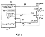
- Lamp 10 designates generally, a deuterium lamp which is used with the invention (FIGURE 1).
- Lamp 10 comprises an envelope 12 and a cathode 14, an anode 16 and a cage 18 mounted inside envelope 12.
- Envelope 12 is filled with a suitable gas such as deuterium and the envelope is sealed.
- Cage 18 is preferably formed of metal and is provided with an arc defining aperture 20.
- Aperture 20 is of the order of 0.5 mm in diameter and serves to concentrate the flow of the electrons toward the center of the anode surface.
- a wire 22 is connected to anode 16 and projects through the envelope 12 to permit the making of the necessary electrical connection to a current limited anode supply 24.
- Two wires 26 and 28 are connected to the filament or heater and project outside the envelope 12 to permit electrical connection to the filament supply 30.
- cathode may be connected to one side of the filament within the lamp. Under such conditions, that side of the filament will be connected to the common or equipment ground.
- the cage 18 (FIGURE 1) is connected within the lamp to a wire 32 which projects outside the envelope so as to be connected to a starting circuit 34.
- the starting circuit 34 supplies a low, positive, current-limited voltage of the order of 30 or so volts to initiate the plasma glow.
- the conductive path between the cathode 14 and the anode 16 is improved and a switcher 36 reduces the current to the cage 18 and permits current to flow between cathode 14 and anode 16 due to the potential difference of 130 to 160 volts.
- the plasma glow achieves a maximum at the set current limit and the lamp is now ready to be used for analysis.
- FIGURES 2 and 3 there are shown two preferred embodiments of a combined switcher and starting circuit to carry out the teachings of the invention. Let us first examine the operation of the circuit of FIGURE 2.
- a switcher-starter circuit 38 is connected to wires 22 and 32 so that the high positive voltage is applied to an anode 16 and the lower positive voltage is applied to a cage 18.
- a conductor 35 serves to connect a common lead 26 to the negative terminal of anode supply 24.
- Switcher-starter 38 comprises a metal oxide voltage dependent resistor (varistor) 40 electrically connected to anode 16 and cage 18.
- the high side of switcher-starter 38 which comprises varistor 40, is electrically connected to anode 16 and the low side is electrically connected to cage 18.
- the output of current limited anode supply 24 is also connected to the high side of switcher-starter 38.
- the filament supply 30 and the anode supply 24 are turned on, there is no electron flow inside the lamp. At this time about 30 volts appears on the cage 18 and a plasma glow initiated by the electron flow between the cathode and the cage appears. As the cage plasma glow increases, the anode plasma glow is initiated by the electron flow between anode 16 and cathode 14. As the anode plasma glow and the current increase, the set anode current limit is reached and the voltage at the anode 16 starts to decrease until a stable condition and the full plasma glow is obtained (approx. 75 to 90 volts). Due to this lower voltage at anode 16 the voltage across the varistor 40 drops below its threshold voltage and current to the cage 18 is reduced appreciably. The anode supply 24 is current limited to prevent the internal lamp current from increasing to a point beyond that necessary to produce full plasma glow. If the anode supply were not so limited, the cathode would evaporate and the lamp would become inoperative.
- Switcher-starter 42 comprises a Zener diode 44 and a current limiting resistor 46 of about 300 ohms or less connected in series. Resistor 46 is connected to the high end of switcher-starter 42 and then to the anode 16. Zener diode 44 is connected to the low end of the switcher-starter and then to the cage 18.
- the supplies are first turned on the low positive voltage is connected to the cage 18 and the plasma glow commences. First, the cage-cathode plasma glow is obtained followed by the anode-cathode plasma glow. The anode voltage drops, as the current limit is reached, and the Zener diode 44 stops conducting. The current to the cage 18 is reduced appreciably and the full current is applied to anode 16 to thereby achieve full plasma glow.
- the switcher-starter circuits shown in FIGURES 2 and 3 may be incorporated on the power supply chassis as indicated diagrammatically in FIGURE 1 or they may be mounted on the lamp's conducting wires as illustrated in FIGURES 4 through 7.
- the small sizes of the circuit elements permit either location.
- FIGURE 4 there is shown, generally, a lamp 110 having an envelope 112, a cathode 114, an anode 116 and a cage 118.
- a varistor 140 is mounted and secured on wires 122 and 132 which are connected to anode 116 and cage 118, respectively.
- Envelope 112 is provide with a cup 152 which is a part of the envelope 112. When all of the parts and connecting wires are in place and all of the necessary tests have been made, the cup 152 is filled with silicone rubber or a similar material so that movement of the parts is precluded.
- a lamp 210 is shown to comprise an envelope 212, an anode 216, a cathode 214, and a cage 218.
- a varistor 240 is connected to the anode 216 through wire 222 and to the cage 218 through wire 232.
- a cap 254 is provided to be moved up to contact envelope 212 and to be cemented thereto after all the necessary tests have been made. Expoxy and cement may be used to hold all the parts under the cap 254 in place and free of breakage in normal use.
- FIGURES 6 and 7 are similar to FIGURES 4 and 5.
- a Zener diode 144 (FIGURE 6) is connected to wire 132 and thence to cage 118 and a resistor 146 in series with Zener diode 144 is connected to wire 122 and anode 116.
- Cup 152 may be and usually is filled with silicone rubber or similar material when all tests are completed.
- a Zener diode 244 is connected to wire 232 and then to cage 218.
- Resistor 246, which is in series with Zener diode 244, is connected to wire 222 and then to anode 216.
- Cap 254 is moved up into contact with envelope 212 after all tests have been completed. Epoxy and cement may be used to keep the elements in place.
- Zener diode It is also possible to use a Zener diode without the series resistor.
- the series resistor serves to limit changes in current such as spikes from being applied to the Zener diode and damaging it.
- the system heater and anode voltages may be turned on simultaneously without the use of delay circuits; second, safety is improved because the low 120 to 160V starting voltage is used; and third, the aperture may be made smaller than those of the prior art to a diameter of about 0.5 mm or less requiring only up to 160V to start operation.
- the prior art lamps require a starting anode voltage of about 400 to 700 volts. Lamps used with the circuits of the present invention will start at voltages as low as 120 volts.
- the invention performs two useful functions: first, the cage serves as a starting electrode to thereby permit the required initial anode voltage to be low; and second, the point source of the ultraviolet is made smaller because the aperture in the cage may be smaller in diameter. It is important for the current in the cage-to-cathode circuit in the lamp to be reduced appreciably as soon as the arc is struck between the cathode and the anode. If this does not occur, sputtering and other spurious effects will occur which will produce inaccuracies and, quite possibly, will destroy the lamp elements.
Landscapes
- Plasma Technology (AREA)
- Circuit Arrangements For Discharge Lamps (AREA)
Claims (10)
- Ein Spannungsversorgungsmittel für eine Deuteriumlampe mit einer gasgefüllten eingeschlossenen Hülle und wenigstens drei in der Hülle montierten Elementen, und zwar einer Kathode (14), einer Anode (16) und einem Mantel (18), die zwischen der Anode, der Kathode und den mit der Kathode assoziierten Heizmitteln angebracht sind, wobei der Mantel eine bogenbestimmende Öffnung mit wenigstens 4 Leitern von der Innenseite der Hülle bis zu deren Außenseite, von denen der erste und der zweite mit den Kathodenheizmitteln (wobei einer der beiden ein gemeinsamer Leiter ist), der dritte mit der Anode und der vierte mit dem Mantel verbunden sind und wobei die Spannungsversorgungsmittel einen ersten Zweipolausgang haben, um die Kathodenheizmittel unter Spannung zu setzen, und einen zweiten, um die Anode unter Spannung zu setzen; kennzeichnend dafür ist es, daß die Spannungsversorgungsmittel einen Schaltkreis (34,36) enthalten, der zwischen der Anode und dem Mantel angebracht werden muß. Der Schaltkreis enthält Mittel, um eine positive Spannung, die niedriger ist als die strombegrenzte Anfangsspannung der Anode, auf den Mantel anzuwenden, um einen Bogenaufbau zwischen der Kathode und dem Mantel auszulösen, wodurch ein Mantelplasmaglühen eingeleitet wird und der Strom zum Mantel herabgesetzt wird, während das Anodenplasmaglühen erhöht wird, und der Anodenhöchststrom erreicht wird.
- Ein Spannungsversorgungsmittel gemäß Patentanspruch 1, bei dem der Schaltkreis zwischen dem dritten und dem vierten Leiter der Lampe geschaltet wird.
- Ein Spannungsversorgungsmittel gemäß Patentanspruch 1, bei dem der Schaltkreis zwischen der gemeinsamen Anschlußklemme des Spannungsversorgungsmittels und der Anodenanschlußklemme des Spannungsversorgungsmittels geschaltet wird. Das Spannungsversorgungsmittel hat eine weitere Anschlußklemme, die mit dem Ausgang der Anschlußklemme mit niedriger, positiver Spannung des Schaltkreises geschaltet ist. Die Anschlußklemme mit niedriger positiven Spannung ist mit dem vierten Leiter, der aus der Lampenhülle hervorragt, verbunden.
- Ein Spannungsversorgungsmittel gemäß Patentanspruch 2 oder 3, bei dem der Schaltkreis einen stromabhängigen Metalloxydwiderstand (Varistor) enthält.
- Ein Spannungsversorgungsmittel gemäß Patentanspruch 2 oder 3, bei dem der Schaltkreis eine Zenerdiode enthält.
- Ein Spannungsversorgungmittel gemäß Patentanspruch 5, das einen mit der Zenerdiode seriengeschalteten Widerstand enthält.
- Eine Deuteriumlampe und ein Spannungsversorgungskreis, die die folgenden Elemente enthalten :
eine Kathode (14), einen Heizkörper für die Kathode, eine Anode (16) und einen leitfähigen Mantel (18), in dem sich eine Öffnung befindet und der zwischen der Kathode und der Anode angebracht wird;
eine gasgefüllte Hülle, die die Kathode, den Heizkörper, die Anode und den Mantel umfaßt;
zwei Klemmendrähte, die vom Heizkörper durch die Hülle hervorragen;
einen Klemmendraht, der von der Anode durch die Hülle hervorragt;
einen Klemmendraht, der vom Mantel durch die Hülle hervorragt; und
ein Mittel, das die Anode und den Mantel mit einem Schaltmittel verbindet. Das Schaltmittel sieht Mittel (34) vor, um auf den Mantel eine positive Spannung anzuwenden, die niedriger ist als die auf die Anode angewandte strombegrenzte Anfangsspannung, wenn zwischen der Kathode und der Anode kein Strom fließt, wodurch ein Strom zwischen der Kathode und dem Mantel fließt, so daß zwischen diesen ein Plasmaglühen ausgelöst wird, und Mittel (36), um den Strom zwischen dem Mantel und der Kathode zu verringern, wenn der Stromfluß zwischen der Anode und der Kathode die vom Mittel (24) zur Versorgung der strombegrenzten Anodenspannung bestimmte Stromgrenze erreicht, wobei in der Lampe ein volles Plasmaglühen entwickelt wird. - Eine Lampe gemäß Patentanspruch 7, bei der das Schaltmittel einen stromabhängigen Metalloxydwiderstand enthält.
- Eine Lampe gemäß Patentanspruch 7, bei der das Schaltmittel eine Zenerdiode enthält.
- Eine Lampe gemäß Patentanspruch 9, die einen mit der Zenerdiode seriengeschalteten Widerstand enthält.
Priority Applications (1)
| Application Number | Priority Date | Filing Date | Title |
|---|---|---|---|
| DE1990607786 DE69007786T2 (de) | 1990-07-09 | 1990-07-09 | Spannungsversorgungsschaltung für Deuteriumlampe. |
Applications Claiming Priority (1)
| Application Number | Priority Date | Filing Date | Title |
|---|---|---|---|
| US07/330,778 US4962335A (en) | 1989-03-30 | 1989-03-30 | Deuterium lamp voltage supply means |
Publications (2)
| Publication Number | Publication Date |
|---|---|
| EP0465735A1 EP0465735A1 (de) | 1992-01-15 |
| EP0465735B1 true EP0465735B1 (de) | 1994-03-30 |
Family
ID=23291293
Family Applications (1)
| Application Number | Title | Priority Date | Filing Date |
|---|---|---|---|
| EP90307456A Expired - Lifetime EP0465735B1 (de) | 1989-03-30 | 1990-07-09 | Spannungsversorgungsschaltung für Deuteriumlampe |
Country Status (2)
| Country | Link |
|---|---|
| US (1) | US4962335A (de) |
| EP (1) | EP0465735B1 (de) |
Cited By (1)
| Publication number | Priority date | Publication date | Assignee | Title |
|---|---|---|---|---|
| DE19901919B4 (de) * | 1998-01-21 | 2005-12-01 | Imaging & Sensing Technology Corp. | Miniatur-Deuteriumbogenlampe |
Families Citing this family (3)
| Publication number | Priority date | Publication date | Assignee | Title |
|---|---|---|---|---|
| US4962335A (en) * | 1989-03-30 | 1990-10-09 | Sonnenschein Armin K | Deuterium lamp voltage supply means |
| CN102053231A (zh) * | 2009-11-04 | 2011-05-11 | 北京普源精电科技有限公司 | 一种包含氘灯电源的测量装置 |
| CN103868594B (zh) * | 2012-12-16 | 2017-06-16 | 北京普源精仪科技有限责任公司 | 一种具有氘灯控制电路的紫外分光光度计 |
Family Cites Families (10)
| Publication number | Priority date | Publication date | Assignee | Title |
|---|---|---|---|---|
| BE353448A (de) * | ||||
| DE639093C (de) * | 1936-11-28 | Siemens Schuckertwerke Akt Ges | Anordnung zur Steuerung von parallel arbeitenden Lichtboegen | |
| US2809317A (en) * | 1949-02-21 | 1957-10-08 | Electro Watt Electrical And In | Device for intensifying an electric current |
| FR997513A (fr) * | 1949-09-17 | 1952-01-07 | Dispositif d'allumage pour tubes fluorescents | |
| US2883584A (en) * | 1955-03-17 | 1959-04-21 | Hivac Ltd | Cold-cathode gas-discharge tubes |
| US3634718A (en) * | 1970-02-06 | 1972-01-11 | Westinghouse Electric Corp | High-pressure gaseous discharge lamp including a starting electrode |
| US3900761A (en) * | 1973-11-30 | 1975-08-19 | Gte Sylvania Inc | High intensity metal arc discharge lamp |
| US4007397A (en) * | 1975-09-02 | 1977-02-08 | General Electric Company | Arc discharge lamp with starter electrode voltage doubling |
| CA1093628A (en) * | 1978-03-16 | 1981-01-13 | Sebastian Y.K. Tam | Device and method of starting a long radiation source |
| US4962335A (en) * | 1989-03-30 | 1990-10-09 | Sonnenschein Armin K | Deuterium lamp voltage supply means |
-
1989
- 1989-03-30 US US07/330,778 patent/US4962335A/en not_active Expired - Lifetime
-
1990
- 1990-07-09 EP EP90307456A patent/EP0465735B1/de not_active Expired - Lifetime
Cited By (1)
| Publication number | Priority date | Publication date | Assignee | Title |
|---|---|---|---|---|
| DE19901919B4 (de) * | 1998-01-21 | 2005-12-01 | Imaging & Sensing Technology Corp. | Miniatur-Deuteriumbogenlampe |
Also Published As
| Publication number | Publication date |
|---|---|
| US4962335A (en) | 1990-10-09 |
| EP0465735A1 (de) | 1992-01-15 |
Similar Documents
| Publication | Publication Date | Title |
|---|---|---|
| US4322658A (en) | High intensity discharge lamp containing electronic starting aid | |
| US4721888A (en) | Arc discharge lamp with ultraviolet enhanced starting circuit | |
| US4135114A (en) | Starting device for discharge lamp | |
| US4316124A (en) | Mixed light arrangement | |
| EP0333359B1 (de) | Anlaufschaltungen für Entladungslampen | |
| GB2089596A (en) | Starter for igniting a gas and/or vapor discharge tube | |
| US3855495A (en) | Flash tube with insulator end cap | |
| US6552502B2 (en) | Light source device | |
| US4604554A (en) | Triggered spark gap discharger | |
| US4860269A (en) | Electrochemical time switching device | |
| EP0465735B1 (de) | Spannungsversorgungsschaltung für Deuteriumlampe | |
| US4494042A (en) | Mercury target sensing and locating apparatus | |
| CA1086814A (en) | Electric discharge lamp with voltage multiplier circuit | |
| JPS6113545A (ja) | 高圧ナトリウム放電灯 | |
| US5261315A (en) | Precision capillary discharge switch | |
| US4465954A (en) | Discharge lamp starting and operating circuit | |
| CA1167973A (en) | Low energy starting aid for high intensity discharge lamps | |
| US3256459A (en) | Arc lamp and method | |
| US4412152A (en) | Discharge lamp with bimetal starter | |
| US4070601A (en) | Circuit arrangement for igniting at least one gas discharge flash tube | |
| EP0082566B1 (de) | Hochdrucknatriumdampfentladungslampe | |
| US4649319A (en) | Gas discharge lamp starter | |
| US4054815A (en) | Circuit arrangement for igniting a gas discharge flash tube | |
| EP0075366A2 (de) | Hochdruckmetalldampfentladungslampe | |
| JPH0548399Y2 (de) |
Legal Events
| Date | Code | Title | Description |
|---|---|---|---|
| PUAI | Public reference made under article 153(3) epc to a published international application that has entered the european phase |
Free format text: ORIGINAL CODE: 0009012 |
|
| AK | Designated contracting states |
Kind code of ref document: A1 Designated state(s): DE GB |
|
| 17P | Request for examination filed |
Effective date: 19920706 |
|
| 17Q | First examination report despatched |
Effective date: 19930621 |
|
| GRAA | (expected) grant |
Free format text: ORIGINAL CODE: 0009210 |
|
| AK | Designated contracting states |
Kind code of ref document: B1 Designated state(s): DE GB |
|
| REF | Corresponds to: |
Ref document number: 69007786 Country of ref document: DE Date of ref document: 19940505 |
|
| PLBE | No opposition filed within time limit |
Free format text: ORIGINAL CODE: 0009261 |
|
| STAA | Information on the status of an ep patent application or granted ep patent |
Free format text: STATUS: NO OPPOSITION FILED WITHIN TIME LIMIT |
|
| 26N | No opposition filed | ||
| PGFP | Annual fee paid to national office [announced via postgrant information from national office to epo] |
Ref country code: GB Payment date: 19970513 Year of fee payment: 8 |
|
| PGFP | Annual fee paid to national office [announced via postgrant information from national office to epo] |
Ref country code: DE Payment date: 19970728 Year of fee payment: 8 |
|
| PG25 | Lapsed in a contracting state [announced via postgrant information from national office to epo] |
Ref country code: GB Free format text: LAPSE BECAUSE OF NON-PAYMENT OF DUE FEES Effective date: 19980709 |
|
| GBPC | Gb: european patent ceased through non-payment of renewal fee |
Effective date: 19980709 |
|
| PG25 | Lapsed in a contracting state [announced via postgrant information from national office to epo] |
Ref country code: DE Free format text: LAPSE BECAUSE OF NON-PAYMENT OF DUE FEES Effective date: 19990501 |