EP0465760B1 - Méthode et appareil pour l'assemblage d'un noyau de transformateur - Google Patents
Méthode et appareil pour l'assemblage d'un noyau de transformateur Download PDFInfo
- Publication number
- EP0465760B1 EP0465760B1 EP91102004A EP91102004A EP0465760B1 EP 0465760 B1 EP0465760 B1 EP 0465760B1 EP 91102004 A EP91102004 A EP 91102004A EP 91102004 A EP91102004 A EP 91102004A EP 0465760 B1 EP0465760 B1 EP 0465760B1
- Authority
- EP
- European Patent Office
- Prior art keywords
- magnetic material
- lamination
- material plates
- plates
- assembling
- Prior art date
- Legal status (The legal status is an assumption and is not a legal conclusion. Google has not performed a legal analysis and makes no representation as to the accuracy of the status listed.)
- Expired - Lifetime
Links
Images

Classifications
-
- H—ELECTRICITY
- H01—ELECTRIC ELEMENTS
- H01F—MAGNETS; INDUCTANCES; TRANSFORMERS; SELECTION OF MATERIALS FOR THEIR MAGNETIC PROPERTIES
- H01F41/00—Apparatus or processes specially adapted for manufacturing or assembling magnets, inductances or transformers; Apparatus or processes specially adapted for manufacturing materials characterised by their magnetic properties
- H01F41/02—Apparatus or processes specially adapted for manufacturing or assembling magnets, inductances or transformers; Apparatus or processes specially adapted for manufacturing materials characterised by their magnetic properties for manufacturing cores, coils, or magnets
- H01F41/0206—Manufacturing of magnetic cores by mechanical means
- H01F41/0213—Manufacturing of magnetic circuits made from strip(s) or ribbon(s)
-
- Y—GENERAL TAGGING OF NEW TECHNOLOGICAL DEVELOPMENTS; GENERAL TAGGING OF CROSS-SECTIONAL TECHNOLOGIES SPANNING OVER SEVERAL SECTIONS OF THE IPC; TECHNICAL SUBJECTS COVERED BY FORMER USPC CROSS-REFERENCE ART COLLECTIONS [XRACs] AND DIGESTS
- Y10—TECHNICAL SUBJECTS COVERED BY FORMER USPC
- Y10T—TECHNICAL SUBJECTS COVERED BY FORMER US CLASSIFICATION
- Y10T29/00—Metal working
- Y10T29/49—Method of mechanical manufacture
- Y10T29/49002—Electrical device making
- Y10T29/4902—Electromagnet, transformer or inductor
- Y10T29/49073—Electromagnet, transformer or inductor by assembling coil and core
-
- Y—GENERAL TAGGING OF NEW TECHNOLOGICAL DEVELOPMENTS; GENERAL TAGGING OF CROSS-SECTIONAL TECHNOLOGIES SPANNING OVER SEVERAL SECTIONS OF THE IPC; TECHNICAL SUBJECTS COVERED BY FORMER USPC CROSS-REFERENCE ART COLLECTIONS [XRACs] AND DIGESTS
- Y10—TECHNICAL SUBJECTS COVERED BY FORMER USPC
- Y10T—TECHNICAL SUBJECTS COVERED BY FORMER US CLASSIFICATION
- Y10T29/00—Metal working
- Y10T29/49—Method of mechanical manufacture
- Y10T29/49002—Electrical device making
- Y10T29/4902—Electromagnet, transformer or inductor
- Y10T29/49075—Electromagnet, transformer or inductor including permanent magnet or core
- Y10T29/49078—Laminated
-
- Y—GENERAL TAGGING OF NEW TECHNOLOGICAL DEVELOPMENTS; GENERAL TAGGING OF CROSS-SECTIONAL TECHNOLOGIES SPANNING OVER SEVERAL SECTIONS OF THE IPC; TECHNICAL SUBJECTS COVERED BY FORMER USPC CROSS-REFERENCE ART COLLECTIONS [XRACs] AND DIGESTS
- Y10—TECHNICAL SUBJECTS COVERED BY FORMER USPC
- Y10T—TECHNICAL SUBJECTS COVERED BY FORMER US CLASSIFICATION
- Y10T29/00—Metal working
- Y10T29/53—Means to assemble or disassemble
- Y10T29/5313—Means to assemble electrical device
- Y10T29/5317—Laminated device
-
- Y—GENERAL TAGGING OF NEW TECHNOLOGICAL DEVELOPMENTS; GENERAL TAGGING OF CROSS-SECTIONAL TECHNOLOGIES SPANNING OVER SEVERAL SECTIONS OF THE IPC; TECHNICAL SUBJECTS COVERED BY FORMER USPC CROSS-REFERENCE ART COLLECTIONS [XRACs] AND DIGESTS
- Y10—TECHNICAL SUBJECTS COVERED BY FORMER USPC
- Y10T—TECHNICAL SUBJECTS COVERED BY FORMER US CLASSIFICATION
- Y10T29/00—Metal working
- Y10T29/53—Means to assemble or disassemble
- Y10T29/5313—Means to assemble electrical device
- Y10T29/53196—Means to apply magnetic force directly to position or hold work part
-
- Y—GENERAL TAGGING OF NEW TECHNOLOGICAL DEVELOPMENTS; GENERAL TAGGING OF CROSS-SECTIONAL TECHNOLOGIES SPANNING OVER SEVERAL SECTIONS OF THE IPC; TECHNICAL SUBJECTS COVERED BY FORMER USPC CROSS-REFERENCE ART COLLECTIONS [XRACs] AND DIGESTS
- Y10—TECHNICAL SUBJECTS COVERED BY FORMER USPC
- Y10T—TECHNICAL SUBJECTS COVERED BY FORMER US CLASSIFICATION
- Y10T29/00—Metal working
- Y10T29/53—Means to assemble or disassemble
- Y10T29/5313—Means to assemble electrical device
- Y10T29/53265—Means to assemble electrical device with work-holder for assembly
Definitions
- This invention relates to method and apparatus for assembling a transformer core based on inserting a lamination of rectangular plates formed of a magnetic material (e.g., silicon steel plates or amorphous magnetic alloy bands) in spaces defined in transformer coils formed of windings of primary and secondary coils, and bringing the opposite end portions of the magnetic material lamination into abutment on each other to form the lamination into an annular shape.
- a magnetic material e.g., silicon steel plates or amorphous magnetic alloy bands
- a transformer core assembly technique such as the one disclosed in Japanese Patent Unexamined Publication No. 63-241911 is known.
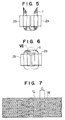
- Fig. 5 shows a state in which laminated core 1 is inserted in coils 2a and 2b.
- the core 1 is formed into an annular shape as shown in Fig. 6.
- Fig. 7 shows an enlarged cross section of a portion VII shown in Fig. 6.
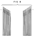
- Fig. 8 shows in an enlarged scale the details of the opposite end portions of laminated magnetic material plates constituting the core 1 in its manufacturing step shown in Fig. 5.
- the above-described well-known technique had a problem of occurrence of large gaps between abutting portions of laminated plates with a resultant increase in the resistance to the magnetic circuit because the abutment-lamination assembly step which influences the core performance was conducted by a manual operation.
- a core formed of an amorphous magnetic alloy had a drawback that the material becomes brittle during a pretreatment step, i.e., core annealing step, so that the core tends to crack or break to deteriorate its characteristics.
- There are further problems in the manual assembling operation two operators are required for the assembling operation because the core and the coils are heavy, and the operation speed is reduced in order to avoid deteriorations in the characteristics pointed out above, resulting in an increase in the assembly costs.
- US-A-3 113 375 discloses a spacing device for spacing separated laminations of a cut core. Since all of the laminations are cut along a single plane it is necessary to space each of the separated laminations a predetermined distance from the subsequently separated lamination.
- the spacing mechanism comprises a driven member in the form of a roller chain which is driven in synchronism with a driven separating member.
- the driven member is provided with a plurality of spacer members which are located at predetermined points along the driven members, such that as laminations are separated from a stack of laminations the end of these separated laminations are removably received by different ones of the spacer members in the form of L-shaped hooks to thereby space such separated laminations from each other.
- the basic principle of the present invention created to achieve this object resides in that in the arrangment shown in Fig. 5, the coils 2a and 2b are electrically energized to magnetize the laminated magnetic material plates constituting the core 1 so that the opposite end portions thereof attract and contact each other by the magnetic force and thus are connected together as shown in Fig. 6.
- a method of assembling a transformer core in which a lamination of rectangular plates formed of a magnetic material is inserted in spaces defined in windings of primary and secondary transformer coils, and in which the opposite end portions of the magnetic material lamination are brought into abutment on each other to form the lamination into an annular shape, said method comprising the steps of: bending the lamination of the rectangular magnetic material plates into a U-shape while the lamination of the magnetic material plates extends through the transformer coils; magnetizing the magnetic material plates by electrically energizing the transformer coils, while restraining the opposite end portions of the U-shaped lamination of the magnetic material plates so as to prevent said end portions from being brought closer to each other; successively releasing the opposite end portions of the U-shaped lamination of the magnetic
- the apparatus arranged to carry out this method of the invention includes: a flat plate on which the lamination of the rectangular magnetic material plates is placed such that the side surfaces of the magnetic material plates at the major side of the rectangle are in abutment with said flat plate; a pair of guide plates having parallel surfaces perpendicular to the flat surface, said guide plates supporting the lamination of the rectangular magnetic material plates so that the magnetic material plates are maintained in a state of being bent in a U-like shape, while the lamination of the magnetic material plates extends through the transformer coils; a pair of pressing members for restraining the opposite end portions of the magnetic material plates bent in the U-like shape from being brought closer to each other; drive means for moving said pair of pressing members step by step toward the open end of the U-like shape; and means for magnetizing the magnetic material plates by electrically energizing the transformer coils.
- the opposite end portions of magnetized rectangular plates of a magnetic material are connected by being brought into abutment against each other by magnetic attraction.
- the restrained opposite end portions of the laminated magnetic material plates are successively released from the innermost opposed ends, so that the ends of the released magnetic material plates successively attract and contact each other and are regularly brought into abutment on each other.
- the assembly operation can be automatically performed and is not laborious since the open ends of the core are bent and connected by magnetic attraction.
- the apparatus constructed as described above has components necessary and sufficient for carrying out the method of the invention, whereby the invention can be carried out easily and positively to fully exhibit its effects.
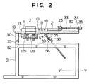
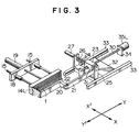
- Fig. 2 is a side view of essential components of an assembly apparatus 3 shown in Fig. 1 taken in the direction of the arrow X′, and Fig. 3 is a perspective view of such components.
- jacks 12a and 12b are mounted on a bracket 11 fixed to a plate 10 and serve to support coils 2 so as to prevent the weight of a core 1 placed on the plate 10 from being applied to the coils 2.
- the core 1 is placed on the plate 10 with its major sides in contact with the plate 10.
- a pinching block 13 for restraining the core 1 from moving is fixed to the plate 10 according to the size and the position of the core 1.
- a channel 13a is formed in the pinching block 13.
- Abutting portions 1R and 1L of the core 1 project out of the coils 2 and are supported from the left and right by a pair of spaced guide plates 14R and 14L so as to be prevented from being deformed outward.
- Slide bars 15 are fixed to the guide plates 14 and are slidably guided by slide bushes 16.
- a cylinder rod 17 is attached at its inner end to each guide plate 14.
- the cylinder rod 17 can be extended or retracted by a cylinder 19 fixed to a bracket 18.
- the guide plates 14 are arranged to facilitate the assembly operation by retracting the cylinder rods 17 to increase the distance between the guide plates 14 when the core 1 and the coils 2 are set on the assembly apparatus 3.
- FIG. 3 shows the left half of the mechanism since this embodiment of the apparatus is symmetric with respect to the longitudinal center line shown by the axis Y.
- Fig. 8 At the open ends of the core 1, groups of core sheets each consisting of one or a plurality of sheets are arranged as shown in Fig. 8. Therefore, when the core 1 is restrained at a desired longitudinal position thereof by a claw 20, the parts of the core sheets located inwardly of the claw 20 are released.
- One end of a bar 21 is fixed to the claw 20 by a pin 22, while the other end of the bar 21 is fixed to a slide block 23.
- Guide bars 24 are disposed so as to extend through the slide block 23.
- the guide bars 24 are fixed to a generally U-shaped bracket 25.
- An inner end of a cylinder rod 26 is secured to the slide block 23.
- the slide block 23 can be slidably moved in the bracket 25 along the guide bars 24 by a cylinder 27 fixed to the bracket 25.
- the bracket 25 is fixed to a nut 31 threadably engaged with a ball screw 30 and to a slide table 32 which can be moved along V guides 33.
- the slide block 23 can therefore be moved in the axial direction of the ball screw 30.
- the rotating shaft of a stepping motor 35 fixed to a bracket 34 is secured to one end of the ball screw 30. Consequently, the nut 31 and slide block 23 guided by the bracket 25 fixed to the slide table 32 and, hence, the bar 21 fixed to the slide block 23 can be moved by the rotation of the stepping motor 35 so that the claw 20 is moved toward the open end of the core 1. Then, the end portion of the core 1 formed of a group of one or a plurality of sheets is disengaged from the claw 20 and released from the restrained state.
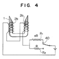
- an arrangement such as one shown in Fig. 4 may be used in which, if a current flows through a primary or secondary coil, the open ends of the core 1 are so energized as to have opposite magnetic polarities, and in which when each of the end portions of the core 1 to be assembled or joined together is released from the claw 20 retracted by a controller (not shown), a relay 40 is immediately changed over to switch from a resistor R1 having a large resistance nR to a resistor R2 having a small resistance R so that the current increases by n times.
- a bracket 50 is fixed to the underside of the plate 10.
- the plate 10 is pivotally connected through a pin 54 to a bearing block 53 provided on a base plate 52 on a base frame 51.
- a bracket 55 is fixed to a generally central portion of the underside of the plate 10 and is pivotally connected to a slide shaft 57 of a jack 56 through a pin 58.
- Transformer coils 2 and a U-shaped core 1 extending therethrough are placed on the thus-constructed assembling apparatus. Then, the left and right guide plates 14L and 14R are moved by the cylinders 19 inwardly of the core 1 and the slide blocks 23 are similarly moved by the cylinders 27. Thereafter, the stepping motors 35L and 35R are operated to move the claws 20 in the direction of the arrow Y′ and then the cylinders 27 are operated to urge the core radially outwardly. Next, the coils 2a and 2b are electrically energized as shown in Fig. 4 and the stepping motor 35L is rotated to a predetermined extent to retract the left claw 20 in the direction of the arrow Y, thereby releasing a portion of the core 1.
- the stepping motor 35R is rotated to a predetermined extent to retract the right claw 20, thereby releasing a corresponding portion of the core 1.
- These core portions attract each other by the magnetic force generated by the coils 2a and 2b so as to minimize the distance between them, so that the gaps G between abutting ends of the laminated sheets of the core are minimized.
- This sequence of operation steps is repeated by the controller (not shown) to effect abutment-lamination assembly of the core 1.
- the operation of abutment-lamination of the core can be automatically performed even if the core is formed of an amorphous alloy magnetic material, and the abutment gaps in the core can be minimized, thus providing a high-performance transformer core.
Landscapes
- Engineering & Computer Science (AREA)
- Power Engineering (AREA)
- Manufacturing & Machinery (AREA)
- Manufacturing Cores, Coils, And Magnets (AREA)
Claims (11)
- Procédé d'assemblage d'un noyau de transformateur (1), dans lequel un ensemble stratifié formé de plaques rectangulaires réalisées en un matériau magnétique est inséré dans des espaces définis dans des enroulements de bobines primaire et secondaire (2a,2b) du transformateur, et dans lequel les parties d'extrémité opposées (1L,1R) de l'ensemble stratifié en matériau magnétique sont amenées réciproquement en aboutement pour donner à l'ensemble stratifié une forme annulaire, ledit procédé comprenant les étapes consistant à :
couder l'ensemble stratifié formé des plaques rectangulaires en matériau magnétique pour lui donner une forme en U, l'ensemble stratifié des plaques en matériau magnétique traversant les bobines (2a, 2b) du transformateur;
aimanter les plaques en matériau magnétique en excitant électriquement les bobines (2a,2b) du transformateur, tout en retenant les parties d'extrémité opposées (1L,1R) de l'ensemble stratifié en forme de U formé par les plaques en matériau magnétique afin d'empêcher que lesdites parties d'extrémité soient plus rapprochées l'une de l'autre;
libérer successivement les parties d'extrémité opposées (1L,1R) de l'ensemble stratifié en forme de U formé par les plaques en matériau magnétique pour qu'elles ne soient pas retenues à partir de l'intérieur; et
amener les parties d'extrémité opposées libérées (1L,1R) de l'ensemble stratifié en forme de U formé par les plaques en matériau magnétique à s'attirer et à venir en contact réciproque intime sous l'effet de la force magnétique. - Procédé d'assemblage d'un noyau de transformateur (1) selon la revendication 1, dans lequel on accroît temporairement le courant d'excitation des bobines (2a,2b) du transformateur chaque fois que des parties de l'ensemble stratifié en forme de U constitué par les plaques en matériau magnétique sont libérées à partir de l'état retenu.
- Procédé d'assemblage d'un noyau de transformateur (1) selon la revendication 1, dans lequel, lorsque des parties de l'ensemble stratifié en forme de U formé par des plaques en matériau magnétique sont successivement libérées de leur état retenu au niveau des parties d'extrémité opposées (1L,1R), la surface latérale rectangulaire des plaques en matériau magnétique sur le grand côté du rectangle est supportée par une plaque lisse et plane (10).
- Procédé d'assemblage d'un noyau de transformateur (1) selon la revendication 3, dans lequel on libère de l'état retenu les parties d'extrémité opposées (1R, 1L) de l'ensemble stratifié en forme de U formé par les plaques en matériau magnétique, tout en faisant pivoter la plaque lisse et plane (10) autour de l'axe perpendiculaire au plan central de la forme en U.
- Procédé d'assemblage d'un noyau de transformateur (1) selon la revendication 1, dans lequel les bobines (2a,2b) du transformateur et les plaques en matériau magnétique sont supportées indépendamment l'une de l'autre de manière à empêcher que le poids de la plaque en matériau magnétique soit supporté par les bobines (2a,2b) du transformateur.
- Procédé d'assemblage d'un noyau de transformateur (1) selon la revendication 1, selon lequel, lorsque les parties d'extrémité opposées (1L,1R) des plaques en matériau magnétique coudées avec la forme en U sont libérées successivement de l'état retenu, une partie centrale de l'ensemble stratifié formé par les plaques en matériau magnétique coudées en forme de U est retenue.
- Procédé d'assemblage d'un noyau de transformateur (1), dans lequel un ensemble stratifié formé de plaques rectangulaires réalisées en un matériau magnétique est inséré dans des espaces définis dans des bobines primaire et secondaire (2a,2b) d'un transformateur formées d'enroulements, et dans lequel les parties d'extrémité opposées (1L,1R) de l'ensemble stratifié en matériau magnétique sont placées réciproquement en aboutement de manière à donner à l'ensemble stratifié une forme annulaire, ledit dispositif comprenant :
une plaque plane (10), sur laquelle l'ensemble stratifié formé des plaques rectangulaires en matériau magnétique est placé de telle sorte que les surfaces latérales des plaques en matériau magnétique sur le grand côté du rectangle sont en aboutement sur ladite plaque plane;
un couple de plaques de guidage (14L,14R) possédant des surfaces parallèles perpendiculaires à la surface plane, lesdites plaques de guidage (14L,14R) supportant l'ensemble stratifié formé des plaques rectangulaires en matériau magnétique de telle sorte que les plaques en matériau magnétique sont maintenues dans un état coudé avec une forme en U, tandis que l'ensemble stratifié formé par les plaques en matériau magnétique traverse les bobines (2a,2b) du transformateur;
un couple d'éléments de serrage (20) pour empêcher que les parties d'extrémité opposées des plaques en matériau magnétique coudées avec une forme en U, soient plus rapprochées l'une de l'autre;
des moyens d'entraînement (35L,35R) pour déplacer lesdits éléments de serrage (20) pas-à-pas en direction de l'extrémité ouverte de la forme en U; et
des moyens pour aimanter les plaques en matériau magnétique au moyen d'une excitation électrique des bobines (2a,2b) du transformateur. - Dispositif pour assembler un noyau de transformateur selon la revendication 7, dans lequel lesdits moyens d'aimantation des bobines (2a,2b) du transformateur incluent un dispositif d'entraînement associé de façon opérationnelle auxdits moyens d'entraînement (35R, 35L) servant à déplacer ledit couple d'éléments de serrage (20), et augmentent de façon temporaire le courant d'excitation chaque fois que lesdits moyens d'entraînement (35R,35L) déplacent lesdits éléments de serrage (20).
- Dispositif pour assembler un noyau de transformateur (1) selon la revendication 7, dans lequel ladite plaque plane (10), sur laquelle les plaques en matériau magnétique sont placées, peut pivoter autour de l'axe perpendiculaire au plan central de la forme en U des plaques coudées en matériau magnétique, et que le dispositif comporte des moyens (57, 59) pour entraîner ladite plaque plane (10) de manière à l'incliner.
- Dispositif pour assembler un noyau de transformateur selon la revendication 7, comprenant en outre des moyens pour guider ledit couple de plaques de guidage (14R,14L) de telle sorte que lesdites plaques de guidage (14R,14L) sont rapprochées ou écartées l'une de l'autre, tandis que leur parallélisme est maintenu, et des moyens (9) pour entraîner lesdites plaques de guidage (14R,14L).
- Dispositif pour assembler un noyau de transformateur selon la revendication 7, comprenant en outre des moyens formant vérins (12a,12b) pour supporter les bobines (2a,2b) du transformateur de manière à régler leur position d'une manière générale dans la direction verticale, lesdits moyens formant vérins (12a,12b) étant prévus indépendamment de ladite plaque plane (10), sur laquelle les plaques en matériau magnétique sont placées.
Applications Claiming Priority (2)
| Application Number | Priority Date | Filing Date | Title |
|---|---|---|---|
| JP175244/90 | 1990-07-04 | ||
| JP2175244A JP2776963B2 (ja) | 1990-07-04 | 1990-07-04 | 変圧器鉄心の組立方法および組立装置 |
Publications (2)
| Publication Number | Publication Date |
|---|---|
| EP0465760A1 EP0465760A1 (fr) | 1992-01-15 |
| EP0465760B1 true EP0465760B1 (fr) | 1995-05-03 |
Family
ID=15992783
Family Applications (1)
| Application Number | Title | Priority Date | Filing Date |
|---|---|---|---|
| EP91102004A Expired - Lifetime EP0465760B1 (fr) | 1990-07-04 | 1991-02-13 | Méthode et appareil pour l'assemblage d'un noyau de transformateur |
Country Status (4)
| Country | Link |
|---|---|
| US (1) | US5046235A (fr) |
| EP (1) | EP0465760B1 (fr) |
| JP (1) | JP2776963B2 (fr) |
| DE (1) | DE69109383T2 (fr) |
Families Citing this family (6)
| Publication number | Priority date | Publication date | Assignee | Title |
|---|---|---|---|---|
| US6374480B1 (en) * | 1998-05-13 | 2002-04-23 | Abb Inc. | Method and apparatus for making a transformer core from amorphous metal ribbons |
| US7373716B2 (en) * | 2003-10-22 | 2008-05-20 | Dexter Magnetic Technologies, Inc. | Method for constructing permanent magnet assemblies |
| US7135792B2 (en) * | 2004-05-12 | 2006-11-14 | Dexter Magnetic Technologies, Inc. | High field voice coil motor |
| CN101944808B (zh) * | 2010-10-19 | 2012-11-07 | 天津市天发重型水电设备制造有限公司 | 一种电机转子线圈扁绕模定位板装配方法 |
| CN106876128B (zh) * | 2017-04-20 | 2018-04-03 | 安徽预立兴川机器人技术股份有限公司 | 一种家电产品变压器组件组装系统 |
| CN106887320B (zh) * | 2017-04-20 | 2018-04-03 | 安徽预立兴川机器人技术股份有限公司 | 一种用于变压器组件磁芯自动送料插装机构 |
Family Cites Families (4)
| Publication number | Priority date | Publication date | Assignee | Title |
|---|---|---|---|---|
| US3003225A (en) * | 1955-09-19 | 1961-10-10 | Mc Graw Edison Co | Method and apparatus for constructing a magnetic core |
| US3113375A (en) * | 1962-10-01 | 1963-12-10 | Gen Electric | Mechanism for spacing separated laminations of a cut core |
| US4734975A (en) * | 1985-12-04 | 1988-04-05 | General Electric Company | Method of manufacturing an amorphous metal transformer core and coil assembly |
| JP2594933B2 (ja) * | 1987-03-30 | 1997-03-26 | 株式会社 ダイヘン | 変圧器の製造方法 |
-
1990
- 1990-07-04 JP JP2175244A patent/JP2776963B2/ja not_active Expired - Fee Related
-
1991
- 1991-02-13 US US07/654,665 patent/US5046235A/en not_active Expired - Fee Related
- 1991-02-13 DE DE69109383T patent/DE69109383T2/de not_active Expired - Fee Related
- 1991-02-13 EP EP91102004A patent/EP0465760B1/fr not_active Expired - Lifetime
Also Published As
| Publication number | Publication date |
|---|---|
| JP2776963B2 (ja) | 1998-07-16 |
| US5046235A (en) | 1991-09-10 |
| DE69109383D1 (de) | 1995-06-08 |
| EP0465760A1 (fr) | 1992-01-15 |
| DE69109383T2 (de) | 1995-09-14 |
| JPH0464208A (ja) | 1992-02-28 |
Similar Documents
| Publication | Publication Date | Title |
|---|---|---|
| US5370324A (en) | Stator winding method and apparatus | |
| CN109216015B (zh) | 环型线圈的自动绕线机 | |
| US6732970B2 (en) | Stator winding and coil lead termination method and apparatus | |
| EP0465760B1 (fr) | Méthode et appareil pour l'assemblage d'un noyau de transformateur | |
| EP0478302B1 (fr) | Procédé et appareil de fabrication d'enroulements statoriques | |
| EP0052852B1 (fr) | Appareil pour l'insertion de bobines | |
| CN112786305B (zh) | 一种配电变压器自动叠片装置 | |
| US3453726A (en) | Method and apparatus for manufacturing a laminated magnetic core | |
| US5001828A (en) | Apparatus for removing coil wire from a stator | |
| CN114188142A (zh) | 一种变压器铁芯的自动剪切叠片装置及方法 | |
| CN116598132A (zh) | 变压器制造用线圈绕线装置 | |
| US4299023A (en) | Machine for winding and inserting coils | |
| US4016639A (en) | Apparatus and method for stripping windings from a stator | |
| CN113451037B (zh) | 一种制作立体卷变压器铁心的方法 | |
| CN118597715A (zh) | 一种硅钢卷带料自动换向回转机 | |
| US4893858A (en) | Movable yoke-type lifting magnet device | |
| US5895004A (en) | Coil winding apparatus for large diameter magnetic rings | |
| JPH1079317A (ja) | 鉄心用非晶質磁性合金薄帯の段積み方法及び装置 | |
| KR20230057090A (ko) | 고정자 코일의 정렬 장치 | |
| JP2002096233A (ja) | リニアスライダ | |
| JP2774898B2 (ja) | モータ用着磁機 | |
| CN215624731U (zh) | 一种多平台间距可调的驱动装置 | |
| CN224020691U (zh) | 汽车电磁开关反绕装置 | |
| CN223534621U (zh) | 一种圆铜线收线成卷机 | |
| CN221416482U (zh) | 一种滤网装配装置 |
Legal Events
| Date | Code | Title | Description |
|---|---|---|---|
| PUAI | Public reference made under article 153(3) epc to a published international application that has entered the european phase |
Free format text: ORIGINAL CODE: 0009012 |
|
| 17P | Request for examination filed |
Effective date: 19910213 |
|
| AK | Designated contracting states |
Kind code of ref document: A1 Designated state(s): DE FR GB |
|
| 17Q | First examination report despatched |
Effective date: 19930503 |
|
| GRAA | (expected) grant |
Free format text: ORIGINAL CODE: 0009210 |
|
| AK | Designated contracting states |
Kind code of ref document: B1 Designated state(s): DE FR GB |
|
| REF | Corresponds to: |
Ref document number: 69109383 Country of ref document: DE Date of ref document: 19950608 |
|
| ET | Fr: translation filed | ||
| PG25 | Lapsed in a contracting state [announced via postgrant information from national office to epo] |
Ref country code: GB Effective date: 19960213 |
|
| PLBE | No opposition filed within time limit |
Free format text: ORIGINAL CODE: 0009261 |
|
| STAA | Information on the status of an ep patent application or granted ep patent |
Free format text: STATUS: NO OPPOSITION FILED WITHIN TIME LIMIT |
|
| 26N | No opposition filed | ||
| GBPC | Gb: european patent ceased through non-payment of renewal fee |
Effective date: 19960213 |
|
| PGFP | Annual fee paid to national office [announced via postgrant information from national office to epo] |
Ref country code: FR Payment date: 19971216 Year of fee payment: 8 |
|
| PGFP | Annual fee paid to national office [announced via postgrant information from national office to epo] |
Ref country code: DE Payment date: 19980325 Year of fee payment: 8 |
|
| PG25 | Lapsed in a contracting state [announced via postgrant information from national office to epo] |
Ref country code: FR Free format text: LAPSE BECAUSE OF NON-PAYMENT OF DUE FEES Effective date: 19991029 |
|
| PG25 | Lapsed in a contracting state [announced via postgrant information from national office to epo] |
Ref country code: DE Free format text: LAPSE BECAUSE OF NON-PAYMENT OF DUE FEES Effective date: 19991201 |
|
| REG | Reference to a national code |
Ref country code: FR Ref legal event code: ST |