EP0465767A1 - Gründungspfahl aus armiertem Beton - Google Patents
Gründungspfahl aus armiertem Beton Download PDFInfo
- Publication number
- EP0465767A1 EP0465767A1 EP91104416A EP91104416A EP0465767A1 EP 0465767 A1 EP0465767 A1 EP 0465767A1 EP 91104416 A EP91104416 A EP 91104416A EP 91104416 A EP91104416 A EP 91104416A EP 0465767 A1 EP0465767 A1 EP 0465767A1
- Authority
- EP
- European Patent Office
- Prior art keywords
- flat steel
- foundation pile
- steel profiles
- drill pipe
- pile according
- Prior art date
- Legal status (The legal status is an assumption and is not a legal conclusion. Google has not performed a legal analysis and makes no representation as to the accuracy of the status listed.)
- Granted
Links
- 239000011150 reinforced concrete Substances 0.000 title 1
- 229910000831 Steel Inorganic materials 0.000 claims abstract description 38
- 239000010959 steel Substances 0.000 claims abstract description 38
- 239000011513 prestressed concrete Substances 0.000 claims description 2
- 239000004567 concrete Substances 0.000 abstract description 2
- 239000011796 hollow space material Substances 0.000 abstract 2
- 238000004519 manufacturing process Methods 0.000 description 3
- XEEYBQQBJWHFJM-UHFFFAOYSA-N Iron Chemical compound [Fe] XEEYBQQBJWHFJM-UHFFFAOYSA-N 0.000 description 2
- 238000000034 method Methods 0.000 description 2
- 238000013459 approach Methods 0.000 description 1
- 230000005540 biological transmission Effects 0.000 description 1
- 229910052742 iron Inorganic materials 0.000 description 1
- 230000002787 reinforcement Effects 0.000 description 1
Images
Classifications
-
- E—FIXED CONSTRUCTIONS
- E02—HYDRAULIC ENGINEERING; FOUNDATIONS; SOIL SHIFTING
- E02D—FOUNDATIONS; EXCAVATIONS; EMBANKMENTS; UNDERGROUND OR UNDERWATER STRUCTURES
- E02D5/00—Bulkheads, piles, or other structural elements specially adapted to foundation engineering
- E02D5/22—Piles
- E02D5/24—Prefabricated piles
- E02D5/30—Prefabricated piles made of concrete or reinforced concrete or made of steel and concrete
-
- E—FIXED CONSTRUCTIONS
- E02—HYDRAULIC ENGINEERING; FOUNDATIONS; SOIL SHIFTING
- E02D—FOUNDATIONS; EXCAVATIONS; EMBANKMENTS; UNDERGROUND OR UNDERWATER STRUCTURES
- E02D5/00—Bulkheads, piles, or other structural elements specially adapted to foundation engineering
- E02D5/22—Piles
- E02D5/56—Screw piles
-
- E—FIXED CONSTRUCTIONS
- E02—HYDRAULIC ENGINEERING; FOUNDATIONS; SOIL SHIFTING
- E02D—FOUNDATIONS; EXCAVATIONS; EMBANKMENTS; UNDERGROUND OR UNDERWATER STRUCTURES
- E02D5/00—Bulkheads, piles, or other structural elements specially adapted to foundation engineering
- E02D5/22—Piles
- E02D5/58—Prestressed concrete piles
Definitions
- the invention is directed to a foundation pile made of reinforced, primarily prestressed concrete with external threads and an internal cavity for engaging the drill rod applying the torsional force.
- the endeavor is therefore aimed at designing foundation piles of the type described at the outset in such a way that they can be produced using the known centrifugal technology in a cost-saving manner and in a quality which cannot be achieved with the production methods used hitherto. It is all about the quality of the piles to improve in that the surface quality is significantly improved and a high degree of crack freedom is achieved.
- At least two flat steel profiles are fastened axially parallel in such a foundation pile in the pile wall at approximately the same angular distance, which project freely with about half their width into the inner cavity serving to engage the drill pipe.
- the measure according to the invention assumes that such flat steel profiles can be fixed exactly in the centrifugal shape without major difficulties, so that when the mast is ejected, the interior of a perfectly circular cross-section practically arises by itself, the flat steel profiles being anchored in the pile wall in such a way that they are anchored are anchored in the wall with about half their width and protrude into the inner cavity of the pile with the other half of their width.
- a mast made in this way has all the advantages of centrifugal technology. It is practically crack-free and has a particularly high surface quality.
- the threads can also be formed in a centrifugal shape of a quality not previously known.
- the invention opens up the possibility in a simple manner of arranging the flat steel profiles in the area bearing the outer threads. In this way, as is known, the torsional forces can be transferred particularly well to the pile.
- Another alternative is that the flat steel profiles are arranged in the upper end region of the pile. This configuration enables better handling when screwing in and allows the use of a shorter drill pipe.
- a further embodiment of the invention are on the flat steel profiles in the area of their upper end in the inside protruding part recesses arranged for engagement of outer lugs attached to the drill pipe.
- the drill pipe is inserted into the inner cavity of the pile until the lugs of the drill pipe face each other in recesses in the flat steel profiles.
- the lugs engage in the recesses and, to a certain extent, lead to a connection between the drill pipe and flat steel profiles according to the bayonet lock principle.
- tensile forces can also be transmitted from the drill pipe to the foundation pile in order to prevent the pile from being over-tightened when the torsional force is applied.
- the drill pipe is designed such that it approximately fills the inner cavity of the pile and has longitudinal incisions for engaging the flat steel profiles. It goes without saying that these cuts and their arrangement correspond to the number and position of the flat iron profiles in the inner cavity of the pile. In this embodiment, the torsional force acts over a considerable length of the pile.
- An alternative embodiment provides that the diameter of the drill pipe is smaller than the radial distance between the flat steel profiles and that external drivers for tangential attack on and / or for engagement in the recesses of the flat steel profiles are arranged on the drill pipe. In the former case, there is a kind of point Attack of the drill pipe on the flat steel profiles anchored in the wall of the pile.
- the invention provides that the flat steel profiles embedded in the wall are fixed on their outer circumference by a plurality of connecting rings spaced apart in the axial direction.
- the foundation pile 1 consists of a shaft 2 made of concrete. It is manufactured using the centrifugal process and has an external thread 4 in the area of its lower end 3 and a base plate 5 at its lower end, to which cutting knives or the like 6 can be attached.
- two eyelets 32 are attached to the head 31 of the pile 1 and are used to handle the pile 1.
- the wall 7 of the pile 1 has a thickness 8 which, in the embodiment shown in the drawing, projects beyond the threads 4 on the outside in the region of the lower end 3 becomes.
- the wall 7 is provided with a reinforcement 9.
- two flat steel profiles 10 are attached so that they are embedded with their outer half 11 in the wall 7, while their inner half 12 by the width 13 in the inner cavity 14 of the pile 1 protrudes.
- the flat steel profiles 10 are welded to the base plate 5 at their lower end 15 in the embodiment shown here. They are also connected by three steel rings 16, 17, 18 arranged at a distance from one another and thus fixed against one another.
- the angular spacing of the two flat steel profiles 10 is in each case 180 ° in the embodiments shown in the drawing.
- a torque is applied to the foundation pile 1 through the drill string 20, which approximately fills the inner cavity 14 in the embodiment shown in FIG. 4.
- the drill pipe is provided with a notch 21, which runs in the longitudinal direction and is brought into alignment with the flat steel profiles 10 when the drill pipe 20 is retracted, so that the profiles 10 when the drill pipe 20 is lowered into the notches 21 of the Intervene in the drill pipe.
- a much thinner drill pipe 22 is used, on the outer wall 23 of which two opposing outer lugs 24 are fastened which, after the drill pipe 22 has been retracted accordingly, act on the flat steel profiles 10 during its rotation and apply their torsional force to them Profiles 10 and thus can be transferred to the shaft 2 of the pile 1.
- the diameter 25 of this drill pipe 22 is slightly smaller than the distance 26 between the two flat steel profiles 10.
- FIG. 6 shows an embodiment in which, in the area of the upper end 27 of the flat steel profiles 10, incisions 28 are made in an opposite arrangement in the part 12 of the flat steel profiles 10 projecting into the inner cavity.
- outer lugs 29 are fastened, which are intended to engage in the incisions 28 in order to be able to transmit a corresponding tensile force in the direction of arrow 30 to the pile 1 from the drill string.
Landscapes
- Engineering & Computer Science (AREA)
- Structural Engineering (AREA)
- Life Sciences & Earth Sciences (AREA)
- General Life Sciences & Earth Sciences (AREA)
- Mining & Mineral Resources (AREA)
- Paleontology (AREA)
- Civil Engineering (AREA)
- General Engineering & Computer Science (AREA)
- Piles And Underground Anchors (AREA)
- Rod-Shaped Construction Members (AREA)
- Bulkheads Adapted To Foundation Construction (AREA)
- Foundations (AREA)
Abstract
Description
- Die Erfindung richtet sich auf einen Gründungspfahl aus armiertem, vornehmlich vorgespannten Beton mit äußeren Gewindegängen und einem Innenhohlraum zum Eingriff des die Torsionskraft aufbringenden Bohrgestänges.
- Die Herstellung solcher Pfähle bereitet erhebliche Schwierigkeiten, die zum einen auf der vor allem durch das Außengewinde komplizierten Formgebung beruhen, zum anderen aber auch auf den hohen Qualitätsansprüchen, die sich vornehmlich aus den aufzunehmenden Kräften beim Eindrehen in das Erdreich ergeben. Nicht weniger Probleme bereitet die Aufgabe, derartige Gründungspfähle in einer zur Aufnahme der erforderlichen Torsionskraft geeigneten Weise kostengünstig herzustellen. Im allgemeinen wird der Innenhohlraum mit einem mehreckigen Querschnitt versehen, in den ein analog gestaltetes Bohrgestänge eingreift. Diese Ausbildung erschwert jedoch die Herstellung dieser Pfähle außerordentlich. In dieser Hinsicht weniger problematisch ist die Verwendung einer an dem Kopf des Pfahles angebrachten Stahlplatte mit einem der Außenkontur des eingreifenden Bohrgestänges entsprechenden Ausschnitt. Die Verwendung einer solchen Kopfstahlplatte ist jedoch außerordentlich kostenintensiv. Sie muß zunächst an dem Pfahl befestigt werden. Zum anderen ist sie aber nach dem Eindrehen des Pfahles im Gebrauchszustand nicht mehr zu nutzen.
- Das Bestreben richtet sich deshalb darauf, Gründungspfähle der eingangs bezeichneten Art so zu gestalten, daß sie unter Anwendung der bekannten Schleudertechnik kostensparend und in einer Qualität hergestellt werden können, die mit den bisher verwendeten Fertigungsmethoden nicht zu erreichen ist. Es geht vor allem darum, die Qualität der Pfähle dadurch zu verbessern, daß die Oberflächengüte entscheidend verbessert und ein hohes Maß an Rissefreiheit erzielt wird. Diese Vorzüge ergeben sich durch die Anwendung des Schleuderverfahrens und der Vorspanntechnik, welche zu einem Gründungspfahl mit einwandfrei zentrisch zu bestimmender Gestaltung des Hohlraums mit einem kreisförmigen Querschnitt führen. Um dann aber die erforderliche Torsionskraft über das Bohrgestänge aufzubringen, sind bei einem solchen Gründungspfahl in der Pfahlwandung in etwa gleichem Winkelabstand mindestens zwei Flachstahlprofile achsparallel befestigt, die mit etwa ihrer halben Breite frei in den zum Eingriff des Bohrgestänges dienenden Innenhohlraum hineinragen.
- Die erfindungsgemäße Maßnahme geht davon aus, daß solche Flachstahlprofile ohne größere Schwierigkeiten in der Schleuderform exakt fixiert werden können, so daß beim Ausschleudern des Mastes der Innenraum von einwandfrei kreisförmigem Querschnitt praktisch von selbst entsteht, wobei in der Pfahlwandung die Flachstahlprofile derart verankert werden, daß sie etwa mit ihrer halben Breite in der Wand verankert sind und mit der anderen Hälfte ihrer Breite in den Innenhohlraum des Pfahls hineinragen. Ein auf diese Weise hergestellter Mast weist alle Vorteile der Schleudertechnik auf. Er ist praktisch rissefrei und weist eine besonders hohe Oberflächengüte auf. Auch lassen sich die Gewindegänge in einer Schleuderform von bisher nicht gekannter Güte ausbilden.
- Im einfachsten Fall werden in die Wandung zwei auf einem Durchmesser einander gegenüberliegende Flachprofile eingebracht. Es können aber durchaus auch drei Profile, um jeweils 120° versetzt, oder auch mehr Profile angebracht werden. Welcher Ausführungsform der Vorzug gegeben wird, richtet sich hierbei nach den Besonderheiten des Einzelfalls.
- Die Erfindung eröffnet in einfacher Weise die Möglichkeit die Flachstahlprofile in dem die äußeren Gewindegänge tragenden Bereich anzuordnen. Auf diese Weise lassen sich, wie bekannt, die Torsionskräfte besonders gut auf den Pfahl übertragen. Eine andere Alternative besteht darin, daß die Flachstahlprofile in dem oberen Endbereich des Pfahls angeordnet sind. Diese Ausgestaltung ermöglicht eine bessere Handhabung beim Eindrehen und gestattet die Anwendung eines kürzeren Bohrgestänges.
- Es liegt im Rahmen der Erfindung, bei einem Gründungspfahl mit einer Schneidmesser tragenden Fußplatte die Flachstahlprofile an dieser Fußplatte zu befestigen, vorzugsweise anzuschweißen. Die zum Eindrehen aufzubringende Torsionskraft wirkt dann unmittelbar über die Fußplatte auf den Fuß des Gründungspfahls ein. Eine demgegenüber andere Alternative verkörpert sich in dem selbständigen Erfindungsgedanken, daß bei einem Gründungspfahl der entsprechenden Gattung an der dem Innenhohlraum zugekehrten Innenfläche der Fußplatte Mitnehmeransätze zum Angriff des Bohrgestänges befestigt sind. Diese Anordnung entspricht der erstgenannten Ausführungsform, jedoch nehmen hier die aus der Pfahlwandung in den Innenhohlraum hineinragenden Flachstahlprofile nur eine extrem kurze Länge an, die in den an der Fußplatte befestigten Ansätzen zum Ausdruck kommt. Es liegt auf der Hand, daß in diesem Fall ein Bohrgestänge von entsprechend großer Länge erforderlich ist, doch hat dies den Vorzug der besseren Kraftübertragung auf die Pfahlspitze.
- In weiterer Ausgestaltung der Erfindung sind an den Flachstahlprofilen im Bereich ihres oberen Endes in dem innen überragenden Teil Ausnehmungen zum Eingriff von am Bohrgestänge angebrachten äußeren Ansätzen angeordnet. Bei dieser Ausführungsform wird das Bohrgestänges soweit in den Innenhohlraum des Pfahls eingefahren, bis die Ansätze des Bohrgestänges in Ausnehmungen der Flachstahlprofile gegenüberstehen. Durch geringfügiges Verdrehen des Bohrgestänges greifen die Ansätze in die Ausnehmungen ein und führen gewissermaßen nach dem Prinzip des Bajonettverschlusses zu einer Verbindung zwischen Bohrgestänge und Flachstahlprofilen. Auf diese Weise können auch Zugkräfte vom Bohrgestänge auf den Gründungspfahl übertragen werden, um ein zu starkes Anziehen des Pfahls beim Aufbringen der Torsionskraft zu verhindern. Damit werden die bisher üblichen Ösen am Kopf des Gründungspfahls entbehrlich, an denen entsprechende Zugmittel angreifen, um eine Zugkraft auf den Pfahl ausüben zu können. Dadurch wird die Handhabung beim Einbringen solcher Gründungspfähle erheblich vereinfacht.
- In weiterer Ausgestaltung des Grundgedankens der Erfindung ist das Bohrgestänge so gestaltet, daß es den Innenhohlraum des Pfahls annähernd ausfüllt und längs verlaufende Einschnitte zum Eingriff der Flachstahlprofile aufweist. Es versteht sich von selbst, daß diese Einschnitte und ihre Anordnung der Zahl und Lage der Flacheisenprofile in dem Innenhohlraum des Pfahls entsprechen. Bei dieser Ausführungsform wird die Torsionskraft über eine beachtliche Länge des Pfahls wirksam. Eine alternative Ausgestaltung sieht hingegen vor, daß der Durchmesser des Bohrgestänges kleiner ist als der radiale Abstand zwischen den Flachstahlprofilen und daß auf dem Bohrgestänge äußere Mitnehmer zum tangentialen Angriff an dem und/oder zum Eingriff in die Ausnehmungen der Flachstahlprofile angeordnet sind. Im erstgenannten Fall ergibt sich ein gewissermaßen punktförmiger Angriff des Bohrgestänges an den in der Wandung des Pfahls verankerten Flachstahlprofilen.
- Die Erfindung sieht schließlich vor, daß die in die Wandung eingebetteten Flachstahlprofile an ihrem Außenumfang durch mehrere in Axialrichtung beabstandete Verbindungsringe fixiert sind.
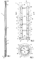
- Weitere Merkmale, Einzelheiten und Vorteile der Erfindung ergeben sich aus der folgenden Beschreibung einiger bevorzugter Ausführungsformen der Erfindung sowie anhand der Zeichnung. Hierbei zeigen:
- Fig. 1
- einen Gründungspfahl in Seitenansicht;
- Fig. 2
- das untere Ende eines Gründungspfahls im Schnitt;
- Fig. 3
- einen Schnitt nach Linie III - III in Fig. 2;
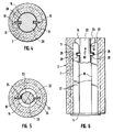
- Fig. 4
- eine erste und
- Fig. 5
- eine zweite Ausführungsform des Bohrgestänges zum Zusammenwirken mit den in den Innenhohlraum ragenden Flachstahlprofilen und
- Fig. 6
- eine weitere Ausgestaltung der Erfindung im Schnitt durch das untere Ende des Pfahls.
- Der Gründungspfahl 1 besteht aus einem Schaft 2 aus Beton. Er ist im Schleuderverfahren hergestellt und trägt im Bereich seines unteren Endes 3 ein Außengewinde 4 und an seinem unteren Ende eine Fußplatte 5, an der Schneidmesser od. dgl. 6 befestigt werden können. Am Kopf 31 des Pfahls 1 sind bei der hier wiedergegebenen Ausführungsform zwei Ösen 32 angebracht, die der Hantierung des Pfahls 1 dienen. Die Wandung 7 des Pfahls 1 hat bei der in den Figuren wiedergegebenen Ausführungsformen eine Dicke 8, die bei der in der Zeichnung wiedergegebenen Ausführungsform im Bereich des unteren Endes 3 von den Gewindegängen 4 außen überragt wird. Die Wandung 7 ist mit einer Armierung 9 versehen. In die Wandung sind im Bereich des die Gewindegänge 4 tragenden unteren Endes 3 zwei Flachstahlprofile 10 so angebracht, daß sie mit ihrer äußeren Hälfte 11 in die Wandung 7 eingebettet sind, während ihre innere Hälfte 12 um die Breite 13 in den Innenhohlraum 14 des Pfahls 1 hineinragt. Die Flachstahlprofile 10 sind bei der hier wiedergegebenen Ausführungsform an ihrem unteren Ende 15 mit der Fußplatte 5 verschweißt. Sie werden darüber hinaus durch drei in Abstand voneinander angeordnete Stahlringe 16, 17, 18 verbunden und damit gegeneinander fixiert. Der Winkelabstand der beiden Flachstahlprofile 10 beträgt bei den in der Zeichnung wiedergegebenen Ausführungsformen jeweils 180°.
- Auf den Gründungspfahl 1 wird ein Drehmoment durch das Bohrgestänge 20 aufgebracht, welches bei der in Fig. 4 wiedergegebenen Ausführungsform den Innenhohlraum 14 annähernd ausfüllt. An zwei diametral gegenüberliegenden Seiten ist das Bohrgestänge mit je einem Einschnitt 21 versehen, der in Längsrichtung verläuft und beim Einfahren des Bohrgestänges 20 mit den Flachstahlprofilen 10 zur Flucht gebracht wird, so daß die Profile 10 beim Absenken des Bohrgestänges 20 schließlich in die Einschnitte 21 des Bohrgestänges eingreifen. Bei der Ausführungsform nach Fig. 5 hingegen findet ein wesentlich dünneres Bohrgestänge 22 Anwendung, an dessen Außenwand 23 zwei einander gegenüberliegende äußere Ansätze 24 befestigt sind, die nach entsprechend weitem Einfahren des Bohrgestänges 22 bei dessen Drehung an den Flachstahlprofilen 10 angreifen und ihre Torsionskraft auf diese Profile 10 und damit auf den Schaft 2 des Pfahls 1 übertragen können. Der Durchmesser 25 dieses Bohrgestänges 22 ist geringfügig kleiner als der Abstand 26 zwischen den beiden Flachstahlprofilen 10.
- Die Fig. 6 zeigt eine Ausführungsform, bei der im Bereich des oberen Endes 27 der Flachstahlprofile 10 in dem in den Innenhohlraum hineinragenden Teil 12 der Flachstahlprofile 10 Einschnitte 28 in gegenüberliegender Anordnung angebracht sind. In entsprechender Weise sind an dem Außenumfang 23 des Bohrgestänges 20 äußere Ansätze 29 befestigt, die zum Eingriff in die Einschnitte 28 bestimmt sind, um eine entsprechende Zugkraft in Pfeilrichtung 30 auf den Pfahl 1 vom Bohrgestänge übertragen zu können.
Claims (9)
- Gründungspfahl aus armiertem, vornehmlich vorgespannten Beton mit äußeren Gewindegängen und einem Innenhohlraum zum Eingriff des die Torsionskraft aufbringenden Bohrgestänges, dadurch gekennzeichnet, daß in der Pfahlwandung (7) in etwa gleichem Winkelabstand mindestens zwei Flachstahlprofile (10) achsparallel befestigt sind, die mit etwa ihrer halben Breite (12) frei in den zum Eingriff des Bohrgestänges (20,22) dienenden Hohlraum (14) hineinragen.
- Gründungspfahl nach Anspruch 1, dadurch gekennzeichnet, daß die Flachstahlprofile (10) in dem die äußeren Gewindegänge (4) tragenden unteren Bereich (3) angeordnet sind.
- Gründungspfahl nach Anspruch 1, dadurch gekennzeichnet, daß die Flachstahlprofile (10) in dem oberen Endbereich angeordnet sind.
- Gründungspfahl nach Anspruch 1 mit einer Messer tragenden Fußplatte, dadurch gekennzeichnet, daß die Flachstahlprofile (10) an der Fußplatte (5) befestigt, vorzugsweise angeschweißt sind.
- Gründungspfahl nach einem der Ansprüche 1 bis 3, dadurch gekennzeichnet, daß an der dem Innenhohlraum (14) zugekehrten Innenfläche der Fußplatte (5) Mitnehmeransätze zum Angriff des Bohrgestänges (20,22) befestigt sind.
- Gründungspfahl nach einem oder mehreren der Ansprüche 1 bis 5, dadurch gekennzeichnet, daß an den Flachstahlprofilen (10) im Bereich ihres oberen Endes (27) in dem inneren überragenden Teil (12) Ausnehmungen (28) zum Eingriff von am Bohrgestänge (22) angebrachten äußeren Ansätzen (29) angeordnet sind.
- Gründungspfahl nach den Ansprüchen 1 bis 5, dadurch gekennzeichnet, daß das Bohrgestänge (20) den Innenhohlraum (14) querschnittlich annähernd ausfüllt und längs verlaufende Einschnitte (21) zum Eingriff der Flachstahlprofile (10) aufweist.
- Gründungspfahl nach den Ansprüchen 1 bis 6, dadurch gekennzeichnet, daß der Durchmesser (25) des Bohrgestänges (22) kleiner ist als der radiale Abstand (26) zwischen den Flachstahlprofilen (10) und auf dem Bohrgestänge (22) äußere Mitnehmer (24) zum tangentialen Eingriff an den und/oder zum Eingriff in die Ausnehmungen (28) der Flachstahlprofile angeordnet sind.
- Gründungspfahl nach mindestens einem der Ansprüche 1 bis 8, dadurch gekennzeichnet, daß die Flachstahlprofile (10) durch mehrere axial beabstandete und an ihrer Außenkante befestigte Ringe (16,17,18) in der Wandung (7) fixiert sind.
Applications Claiming Priority (2)
| Application Number | Priority Date | Filing Date | Title |
|---|---|---|---|
| DE4020757A DE4020757C2 (de) | 1990-06-29 | 1990-06-29 | Gründungspfahl aus armiertem Beton sowie Verfahren zu seiner Herstellung |
| DE4020757 | 1990-06-29 |
Publications (2)
| Publication Number | Publication Date |
|---|---|
| EP0465767A1 true EP0465767A1 (de) | 1992-01-15 |
| EP0465767B1 EP0465767B1 (de) | 1993-09-15 |
Family
ID=6409351
Family Applications (1)
| Application Number | Title | Priority Date | Filing Date |
|---|---|---|---|
| EP91104416A Expired - Lifetime EP0465767B1 (de) | 1990-06-29 | 1991-03-21 | Gründungspfahl aus armiertem Beton |
Country Status (10)
| Country | Link |
|---|---|
| US (1) | US5188485A (de) |
| EP (1) | EP0465767B1 (de) |
| AT (1) | ATE94600T1 (de) |
| AU (1) | AU634067B2 (de) |
| DE (3) | DE9007428U1 (de) |
| DK (1) | DK0465767T3 (de) |
| ES (1) | ES2044637T3 (de) |
| MY (1) | MY106382A (de) |
| NZ (1) | NZ238737A (de) |
| YU (1) | YU107991A (de) |
Families Citing this family (8)
| Publication number | Priority date | Publication date | Assignee | Title |
|---|---|---|---|---|
| US5374140A (en) * | 1990-07-03 | 1994-12-20 | Standish; Peter N. | Drillable ground support bolt |
| US6019549A (en) * | 1996-06-11 | 2000-02-01 | Corrosion Control International Llc | Vortex shedding strake wraps for submerged pilings and pipes |
| DE19743415A1 (de) * | 1997-10-01 | 1999-06-10 | Josef Dipl Ing Behrens | Selbstbohrender Betonpfahl |
| US6030150A (en) * | 1998-02-25 | 2000-02-29 | Dana A. Schmednecht | Method and apparatus for constructing subterranean walls comprised of granular material |
| WO1999046449A1 (en) * | 1998-03-10 | 1999-09-16 | Nippon Steel Corporation | Rotation buried pile and execution management method therefor |
| US6951437B2 (en) * | 2004-02-20 | 2005-10-04 | Hall David B | Foundation support system and method |
| CN100447346C (zh) * | 2005-01-18 | 2008-12-31 | 周兆弟 | 筋状管桩 |
| CN115030213B (zh) * | 2022-05-26 | 2023-04-11 | 上海勘测设计研究院有限公司 | 一种适用于海上风电基桩的工装以及应用方法 |
Citations (5)
| Publication number | Priority date | Publication date | Assignee | Title |
|---|---|---|---|---|
| EP0127221A1 (de) * | 1983-05-03 | 1984-12-05 | Pieter Faber | Betongründungspfahl und Vorrichtung zum Einbringen desselben in den Boden |
| US4543015A (en) * | 1983-09-14 | 1985-09-24 | Kruse William E | Pile having wedge former |
| US4627769A (en) * | 1980-01-14 | 1986-12-09 | Paul Lee | Concrete foundation pile |
| GB2181174A (en) * | 1985-10-03 | 1987-04-15 | Yitshaq Lipsker | A pile and method of installation thereof |
| DE3617025A1 (de) * | 1986-05-21 | 1987-11-26 | Delmag Maschinenfabrik | Vorgefertigter betonpfahl sowie verfahren und vorrichtung zu seinem einbringen ins erdreich |
Family Cites Families (15)
| Publication number | Priority date | Publication date | Assignee | Title |
|---|---|---|---|---|
| US137744A (en) * | 1873-04-08 | Ichabod m | ||
| US1907811A (en) * | 1931-07-01 | 1933-05-09 | August A Hollos | Anchor post |
| US2080181A (en) * | 1935-04-02 | 1937-05-11 | Gideon D Miller | Coal undercutting machine |
| US2088759A (en) * | 1937-02-04 | 1937-08-03 | Central Mine Equipment Co | Mining drill |
| FR843499A (fr) * | 1938-09-15 | 1939-07-04 | Pieu-taraud tubulaire en béton armé à pointe indépendante amovible et dispositifpar rotation et frappe combinées | |
| US2210296A (en) * | 1939-09-23 | 1940-08-06 | Hardsocg Mfg Company | Means for connecting miners' extension drills |
| US2372269A (en) * | 1942-03-12 | 1945-03-27 | Emil V Lapezenski | Theft resisting nut and wrench combination |
| US3295572A (en) * | 1959-05-18 | 1967-01-03 | Hi Shear Corp | Screw and screw driver coupling |
| US3178210A (en) * | 1963-12-11 | 1965-04-13 | Mobile Drilling Co Inc | Hollow auger |
| US3369441A (en) * | 1966-05-04 | 1968-02-20 | Anchor Engineering Co | Fastener with tapered tool engaging surfaces |
| US4239419A (en) * | 1977-10-27 | 1980-12-16 | Gillen William F Jr | Precast concrete threaded pilings |
| JPS5854211B2 (ja) * | 1979-10-31 | 1983-12-03 | 日本サミコン株式会社 | ねじり貫入式pcらせん杭 |
| IT1147107B (it) * | 1981-04-17 | 1986-11-19 | Fondedile Spa | Procedimento per l'esecuzione di cavi anulari per scopi diversi, tra i quali, costruzione di pali di fondazione ad anima cava ed attrezzo relativo |
| JPS60246923A (ja) * | 1984-05-18 | 1985-12-06 | Daido Concrete Kogyo Kk | 基礎くいの回転装置 |
| DE3624943A1 (de) * | 1986-07-23 | 1988-01-28 | Delmag Maschinenfabrik | Vorgefertigtes betonteil sowie verfahren zum einbringen eines solchen in das erdreich |
-
1990
- 1990-06-29 DE DE9007428U patent/DE9007428U1/de not_active Expired - Lifetime
- 1990-06-29 DE DE4020757A patent/DE4020757C2/de not_active Expired - Fee Related
-
1991
- 1991-03-21 AT AT91104416T patent/ATE94600T1/de not_active IP Right Cessation
- 1991-03-21 DE DE91104416T patent/DE59100377D1/de not_active Expired - Fee Related
- 1991-03-21 DK DK91104416.2T patent/DK0465767T3/da active
- 1991-03-21 EP EP91104416A patent/EP0465767B1/de not_active Expired - Lifetime
- 1991-03-21 ES ES91104416T patent/ES2044637T3/es not_active Expired - Lifetime
- 1991-06-07 AU AU78257/91A patent/AU634067B2/en not_active Ceased
- 1991-06-11 MY MYPI91001029A patent/MY106382A/en unknown
- 1991-06-18 YU YU107991A patent/YU107991A/sh unknown
- 1991-06-18 US US07/717,239 patent/US5188485A/en not_active Expired - Fee Related
- 1991-06-27 NZ NZ238737A patent/NZ238737A/xx unknown
Patent Citations (5)
| Publication number | Priority date | Publication date | Assignee | Title |
|---|---|---|---|---|
| US4627769A (en) * | 1980-01-14 | 1986-12-09 | Paul Lee | Concrete foundation pile |
| EP0127221A1 (de) * | 1983-05-03 | 1984-12-05 | Pieter Faber | Betongründungspfahl und Vorrichtung zum Einbringen desselben in den Boden |
| US4543015A (en) * | 1983-09-14 | 1985-09-24 | Kruse William E | Pile having wedge former |
| GB2181174A (en) * | 1985-10-03 | 1987-04-15 | Yitshaq Lipsker | A pile and method of installation thereof |
| DE3617025A1 (de) * | 1986-05-21 | 1987-11-26 | Delmag Maschinenfabrik | Vorgefertigter betonpfahl sowie verfahren und vorrichtung zu seinem einbringen ins erdreich |
Also Published As
| Publication number | Publication date |
|---|---|
| DE4020757C2 (de) | 1996-08-01 |
| US5188485A (en) | 1993-02-23 |
| AU7825791A (en) | 1992-01-02 |
| DK0465767T3 (da) | 1994-01-03 |
| YU107991A (sh) | 1995-03-27 |
| ES2044637T3 (es) | 1994-01-01 |
| DE9007428U1 (de) | 1991-09-19 |
| ATE94600T1 (de) | 1993-10-15 |
| MY106382A (en) | 1995-05-30 |
| NZ238737A (en) | 1993-05-26 |
| DE59100377D1 (de) | 1993-10-21 |
| EP0465767B1 (de) | 1993-09-15 |
| AU634067B2 (en) | 1993-02-11 |
| DE4020757C1 (de) | 1991-12-12 |
Similar Documents
| Publication | Publication Date | Title |
|---|---|---|
| DE1625417C3 (de) | Selbstbohrende und gewindeformende Schraube | |
| EP1105597B1 (de) | Befestigungsvorrichtung für stäbe, pfosten, masten oder dgl. im erdreich und verfahren zur herstellung einer befestigungsvorrichtung | |
| EP2171179B1 (de) | Bohrfundament | |
| DE2444899C2 (de) | Bohrwerkzeug mit Bohrer und Aufnahmeteil | |
| EP2321542B1 (de) | Schraubenantriebsausbildung | |
| DE4113381A1 (de) | Verankerungsanordnung und verankerungsverfahren | |
| EP2689071B1 (de) | Grundankersystem | |
| EP0713014A2 (de) | Ankerbolzen zur Verankerung mittels einer Verbundmasse | |
| EP0465767B1 (de) | Gründungspfahl aus armiertem Beton | |
| DE2535066A1 (de) | Verfahren zum spreizdruckfreien setzen von duebeln sowie werkzeug und duebel zur durchfuehrung des verfahrens | |
| DE3910627C2 (de) | ||
| DE102013102004A1 (de) | Spannvorrichtung | |
| DE1652483B1 (de) | Hydraulisch betaetigtes Geraet zum mechanischen Zerlegen von Gestein | |
| DE2108264C3 (de) | Ankerbolzen für einen Betonanker | |
| DE3633628A1 (de) | Verankerungselement, insbesondere duebel | |
| DE8903163U1 (de) | Stab für eine mehrdimensionale Gerüstkonstruktion | |
| WO1988009708A1 (fr) | Outil de vissage et vis utilisables avec cet outil | |
| DE3829216C2 (de) | ||
| DE69006691T2 (de) | Bohrspitze und Grundbohrvorrichtung. | |
| DE975906C (de) | Verankerung fuer Bewehrungsstaebe in Beton | |
| EP0881400A1 (de) | Befestigungsschraube, insbesondere Rohrschraube | |
| DE1303834C2 (de) | Messpunktmarkierung fuer unterirdische vermarkung | |
| AT291123B (de) | Stahlbetonfertigteilpfahl, welcher in den Baugrund vorzugsweise motorisch eingeschraubt wird | |
| DE4105738C2 (de) | Dreh-Schlag-Bohrwerkzeug sowie Verfahren zur Gesteinsbohrung | |
| CH681649A5 (en) | Self-tapping screw |
Legal Events
| Date | Code | Title | Description |
|---|---|---|---|
| PUAI | Public reference made under article 153(3) epc to a published international application that has entered the european phase |
Free format text: ORIGINAL CODE: 0009012 |
|
| AK | Designated contracting states |
Kind code of ref document: A1 Designated state(s): AT BE CH DE DK ES FR GB GR IT LI LU NL SE |
|
| 17P | Request for examination filed |
Effective date: 19920109 |
|
| 17Q | First examination report despatched |
Effective date: 19930209 |
|
| GRAA | (expected) grant |
Free format text: ORIGINAL CODE: 0009210 |
|
| AK | Designated contracting states |
Kind code of ref document: B1 Designated state(s): AT BE CH DE DK ES FR GB GR IT LI LU NL SE |
|
| REF | Corresponds to: |
Ref document number: 94600 Country of ref document: AT Date of ref document: 19931015 Kind code of ref document: T |
|
| ITF | It: translation for a ep patent filed | ||
| REF | Corresponds to: |
Ref document number: 59100377 Country of ref document: DE Date of ref document: 19931021 |
|
| ET | Fr: translation filed | ||
| REG | Reference to a national code |
Ref country code: GR Ref legal event code: FG4A Free format text: 3009154 |
|
| GBT | Gb: translation of ep patent filed (gb section 77(6)(a)/1977) |
Effective date: 19931103 |
|
| REG | Reference to a national code |
Ref country code: ES Ref legal event code: FG2A Ref document number: 2044637 Country of ref document: ES Kind code of ref document: T3 |
|
| REG | Reference to a national code |
Ref country code: DK Ref legal event code: T3 |
|
| EPTA | Lu: last paid annual fee | ||
| PLBE | No opposition filed within time limit |
Free format text: ORIGINAL CODE: 0009261 |
|
| STAA | Information on the status of an ep patent application or granted ep patent |
Free format text: STATUS: NO OPPOSITION FILED WITHIN TIME LIMIT |
|
| 26N | No opposition filed | ||
| EAL | Se: european patent in force in sweden |
Ref document number: 91104416.2 |
|
| PGFP | Annual fee paid to national office [announced via postgrant information from national office to epo] |
Ref country code: DK Payment date: 19971215 Year of fee payment: 8 |
|
| PGFP | Annual fee paid to national office [announced via postgrant information from national office to epo] |
Ref country code: SE Payment date: 19971223 Year of fee payment: 8 |
|
| PGFP | Annual fee paid to national office [announced via postgrant information from national office to epo] |
Ref country code: LU Payment date: 19980115 Year of fee payment: 8 |
|
| PGFP | Annual fee paid to national office [announced via postgrant information from national office to epo] |
Ref country code: CH Payment date: 19980120 Year of fee payment: 8 |
|
| PGFP | Annual fee paid to national office [announced via postgrant information from national office to epo] |
Ref country code: GR Payment date: 19980306 Year of fee payment: 8 |
|
| PGFP | Annual fee paid to national office [announced via postgrant information from national office to epo] |
Ref country code: ES Payment date: 19980311 Year of fee payment: 8 |
|
| PGFP | Annual fee paid to national office [announced via postgrant information from national office to epo] |
Ref country code: AT Payment date: 19980327 Year of fee payment: 8 |
|
| PGFP | Annual fee paid to national office [announced via postgrant information from national office to epo] |
Ref country code: BE Payment date: 19980402 Year of fee payment: 8 |
|
| PG25 | Lapsed in a contracting state [announced via postgrant information from national office to epo] |
Ref country code: LU Free format text: LAPSE BECAUSE OF NON-PAYMENT OF DUE FEES Effective date: 19990321 Ref country code: AT Free format text: LAPSE BECAUSE OF NON-PAYMENT OF DUE FEES Effective date: 19990321 |
|
| PG25 | Lapsed in a contracting state [announced via postgrant information from national office to epo] |
Ref country code: SE Free format text: LAPSE BECAUSE OF NON-PAYMENT OF DUE FEES Effective date: 19990322 Ref country code: ES Free format text: LAPSE BECAUSE OF NON-PAYMENT OF DUE FEES Effective date: 19990322 |
|
| PG25 | Lapsed in a contracting state [announced via postgrant information from national office to epo] |
Ref country code: LI Free format text: LAPSE BECAUSE OF NON-PAYMENT OF DUE FEES Effective date: 19990331 Ref country code: GR Free format text: LAPSE BECAUSE OF NON-PAYMENT OF DUE FEES Effective date: 19990331 Ref country code: DK Free format text: LAPSE BECAUSE OF NON-PAYMENT OF DUE FEES Effective date: 19990331 Ref country code: CH Free format text: LAPSE BECAUSE OF NON-PAYMENT OF DUE FEES Effective date: 19990331 Ref country code: BE Free format text: LAPSE BECAUSE OF NON-PAYMENT OF DUE FEES Effective date: 19990331 |
|
| PGFP | Annual fee paid to national office [announced via postgrant information from national office to epo] |
Ref country code: FR Payment date: 19990428 Year of fee payment: 9 |
|
| PGFP | Annual fee paid to national office [announced via postgrant information from national office to epo] |
Ref country code: GB Payment date: 19990504 Year of fee payment: 9 |
|
| PGFP | Annual fee paid to national office [announced via postgrant information from national office to epo] |
Ref country code: NL Payment date: 19990527 Year of fee payment: 9 Ref country code: DE Payment date: 19990527 Year of fee payment: 9 |
|
| BERE | Be: lapsed |
Owner name: PFLEIDERER VERKEHRSTECHNIK G.M.B.H. & CO. K.G. Effective date: 19990331 |
|
| EUG | Se: european patent has lapsed |
Ref document number: 91104416.2 |
|
| REG | Reference to a national code |
Ref country code: CH Ref legal event code: PL |
|
| EUG | Se: european patent has lapsed |
Ref document number: 91104416.2 |
|
| REG | Reference to a national code |
Ref country code: FR Ref legal event code: CD |
|
| REG | Reference to a national code |
Ref country code: DK Ref legal event code: EBP |
|
| PG25 | Lapsed in a contracting state [announced via postgrant information from national office to epo] |
Ref country code: GB Free format text: LAPSE BECAUSE OF NON-PAYMENT OF DUE FEES Effective date: 20000321 |
|
| PG25 | Lapsed in a contracting state [announced via postgrant information from national office to epo] |
Ref country code: NL Free format text: LAPSE BECAUSE OF NON-PAYMENT OF DUE FEES Effective date: 20001001 |
|
| GBPC | Gb: european patent ceased through non-payment of renewal fee |
Effective date: 20000321 |
|
| PG25 | Lapsed in a contracting state [announced via postgrant information from national office to epo] |
Ref country code: FR Free format text: LAPSE BECAUSE OF NON-PAYMENT OF DUE FEES Effective date: 20001130 |
|
| NLV4 | Nl: lapsed or anulled due to non-payment of the annual fee |
Effective date: 20001001 |
|
| REG | Reference to a national code |
Ref country code: FR Ref legal event code: ST |
|
| PG25 | Lapsed in a contracting state [announced via postgrant information from national office to epo] |
Ref country code: DE Free format text: LAPSE BECAUSE OF NON-PAYMENT OF DUE FEES Effective date: 20010103 |
|
| REG | Reference to a national code |
Ref country code: ES Ref legal event code: FD2A Effective date: 20000411 |
|
| PG25 | Lapsed in a contracting state [announced via postgrant information from national office to epo] |
Ref country code: IT Free format text: LAPSE BECAUSE OF NON-PAYMENT OF DUE FEES;WARNING: LAPSES OF ITALIAN PATENTS WITH EFFECTIVE DATE BEFORE 2007 MAY HAVE OCCURRED AT ANY TIME BEFORE 2007. THE CORRECT EFFECTIVE DATE MAY BE DIFFERENT FROM THE ONE RECORDED. Effective date: 20050321 |