EP0465777A1 - Poutre en treillis - Google Patents
Poutre en treillis Download PDFInfo
- Publication number
- EP0465777A1 EP0465777A1 EP91106474A EP91106474A EP0465777A1 EP 0465777 A1 EP0465777 A1 EP 0465777A1 EP 91106474 A EP91106474 A EP 91106474A EP 91106474 A EP91106474 A EP 91106474A EP 0465777 A1 EP0465777 A1 EP 0465777A1
- Authority
- EP
- European Patent Office
- Prior art keywords
- lattice girder
- loops
- girder according
- lattice
- connecting rods
- Prior art date
- Legal status (The legal status is an assumption and is not a legal conclusion. Google has not performed a legal analysis and makes no representation as to the accuracy of the status listed.)
- Withdrawn
Links
Images


Classifications
-
- E—FIXED CONSTRUCTIONS
- E04—BUILDING
- E04C—STRUCTURAL ELEMENTS; BUILDING MATERIALS
- E04C5/00—Reinforcing elements, e.g. for concrete; Auxiliary elements therefor
- E04C5/01—Reinforcing elements of metal, e.g. with non-structural coatings
- E04C5/06—Reinforcing elements of metal, e.g. with non-structural coatings of high bending resistance, i.e. of essentially three-dimensional [3D] extent, e.g. lattice girders
- E04C5/065—Light-weight girders, e.g. with precast parts
Definitions
- the invention relates to a lattice girder according to the preamble of claim 1.
- the two connecting rods are usually connected on one side to the upper flange and on the other side to a lower flange.
- the two connecting rods are arranged in such a way that the V-shaped areas with the upper and lower reversal areas are congruently opposite one another.
- the use of the known lattice girders for the production of precast concrete elements, such as hollow wall elements, beam or ribbed ceilings, is carried out in such a way that the lattice girders with their lower chords are placed on reinforcement meshes, such as reinforcement mats or the like, which are arranged on formwork panels, in a first step .
- Concrete is applied to this arrangement, for example to form a first wall area of a double-walled precast concrete part.
- the lattice girders are partially embedded in the first wall area; a part with the top chord protrudes from the first wall area in a second step, the hardened first wall area is held at an appropriate distance from another reinforcement mesh arranged on a formwork area so that a second wall area can be formed by applying concrete.
- the lattice girders are embedded in the second wall area with their area adjacent to the upper chord.
- the part of the lattice girder lying between the two wall areas can also be filled with concrete using suitably arranged formwork.
- a lattice girder is also known (EP-A2-0 355 776), in which separately formed V-shaped sections are arranged instead of continuous connecting rods.
- the V-shaped sections should be arranged in the longitudinal direction of the lattice girder with different base distances.
- the invention has for its object to provide a simply constructed and easy to manufacture lattice girder that is easy to use with sufficient anchoring effect and that enables at least partially automated production of precast concrete parts.
- the arrangement of loops can also increase the stability of the lattice girders in relation to reinforcement nets.
- lattice girders can also be placed in such a way that they are placed on reinforcement meshes essentially over the top and bottom chords.
- lower reversal areas form loops of at least one connecting rod.
- a lattice girder is thus designed such that it can be securely anchored to an assigned reinforcement net or a wall area simply by placing it both in the area of the upper chord and of the lower chord or chords over the respective loops.
- the first and second work steps can thus be automated in a simple manner, because the arrangement of the loops means that no further measures are required for locking against the assigned reinforcement nets or for anchoring in the associated wall areas.
- the formation and arrangement of loops also leads to an essentially uniform introduction or transmission of force. This is particularly advantageous in the area of the top chords.
- the two connecting rods are assigned to one another in such a way that the V-shaped sections of the two connecting rods are offset from one another in the longitudinal direction. This simply results in an arrangement of the claws which increases the anchoring effect and possibly also the stability fen.
- the connecting rods can be arranged in a particularly advantageous manner so that there are essentially the same distances between alternately arranged loops of the two connecting rods.
- the reversed regions bent over to form loops can advantageously have end sections provided with at least one rounded section.
- the end sections can be substantially semicircular, for example. They can also be designed, for example, in a wave-like manner in a manner that increases the support surface or the anchoring surface and / or can comprise straight-line sections.
- the reversal areas can also comprise sections of the legs of the V-shaped sections. The length of the loops and thus the size of the support / connection areas formed thereby can be easily adapted to the respective requirements.
- the loops of the upper reversal areas and / or those of the lower reversal areas are each bent in the opposite direction in at least one connecting rod.
- the loops opposite the upper chord are arranged in a direction pointing away from the upper chord.
- the area opposite the upper chord between the two connecting rods is thus accessible from the outside; Despite arranging the loops, the lattice girders can therefore be stacked. This contributes to a simplification of the handling as well as the transportation and storage of the lattice girders and extends the possibilities for using the lattice girders for the automated production of precast concrete parts.
- the two connecting rods of a lattice girder are of identical design. This enables the lattice girder to be produced in a particularly simple manner.
- the two connecting rods can be formed in one piece with one another.
- the upper chord and the lower chord (s) are only to be assigned to a single connecting rod designed in this way and to be connected to the latter, for example by welding.
- two lower chords are arranged.
- the anchoring of the lattice girder and its stability can be further increased in a simple manner by way of the dimensional stability.
- Each lower flange can be arranged so that it rests on the loops of the associated connecting rod. This location assignment simplifies the manufacture of the lattice girders.
- spacers are arranged on the loops and / or lower chords and / or the upper chord.
- a lattice girder according to one or more of the features mentioned can be used for the production of hollow-walled wall or ceiling elements or the like produced as prefabricated concrete parts.
- the inventive anchoring of the lattice girders over the loops in relation to the wall areas creates the prerequisites for automating the production of such precast concrete parts.
- the design and arrangement of the loops ensures that, for example, when fresh concrete is poured into a cavity between two wall areas, the lattice girders do not tear out of their embedding in the previously formed wall areas due to the pressure that occurs.
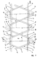
- the first exemplary embodiment shown in FIGS. 1 to 3 for a lattice girder generally designated 1 has two connecting rods 3 of the same design.
- the connecting rods 3 are each made in one piece from a continuous round steel. As can be seen from FIG. 1, they are essentially zigzag-shaped, with V-shaped sections 4 adjoining one another.
- the two connecting rods 3 with an upper chord 7 as apex are arranged at an angle a to one another.
- the arrangement of the two connecting rods 3 is such that each of the two connecting rods 3 is inclined by an angle corresponding to half of the angle a relative to a vertical plane 9 running through the longitudinal axis of the upper chord 7.
- the connecting rods 3 have upper and lower rounded reversing areas 11 and 13, respectively, which are shown in broken lines in FIG. 1.
- the identically designed upper and lower reversing areas 11, 13 each consist of a rounded end section 8 with a radius R and adjoining areas which are formed by an extension of the legs 5, 6 of the V-shaped sections.
- the upper and lower reversing areas 11, 13 are each bent over to form loops.
- the loops which are identical in design to the upper and lower reversal areas 11, 13 according to the present exemplary embodiment are provided with reference numerals 15 and 17 for loops formed from upper reversal areas 11 and lower reversal areas 13, respectively.
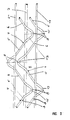
- Adjacent to the legs 5, 6 of both connecting rods 3, a lower flange 19, 21 is arranged on the lower loops 17 of each connecting rod 3.
- the lower flange 19, 21 lies on the respectively assigned lower loop 17 and is connected to it, for example by welding.
- Each of the lower chords 19, 21 can also be connected to a leg 5, 6, which respectively adjoins a loop 17, or a curved transition region 23 between loops 17 and legs 5, 6.
- the curved transition regions 23, which correspond to curved transition regions 23 between the upper loops 13 and the legs 5, 6, have a radius of curvature R in the present exemplary embodiment.
- the upper and lower loops 15, 17 of each connecting rod 3 have a different direction and the connecting rods 3 are assigned to the upper chord 7 and the lower chords 19, 21 such that the loops are separated from the lower chords 19, 21 extend in a direction pointing away from the upper chord 7 or the vertical plane 9.
- the lattice girder is open at the bottom and therefore stackable. Lattice girders according to the invention can thus be transported, stored and picked up from a stack in a simple manner in spite of the loops 15, 17 formed, which enables the lattice girders 1 according to the invention to be used in the automated production of precast concrete parts.
- the upper and lower loops 15, 17 are further designed so that they each run essentially in horizontal planes perpendicular to the vertical plane 9.
- the two connecting rods 3 are arranged so that the upper loops 15 arranged above the upper chord 7 and connected to it, for example by welding, lie in a common horizontal plane. Accordingly, the lower loops 17 located below the lower chords 19, 21 are also arranged in a common horizontal plane.
- the arrangement of loops 15 in the area of the upper chord 7 is particularly important because the area of attachment / anchoring there is smaller than in the area of the lower chords. Due to the anchoring security resulting from the formation and arrangement of the loops 15, 17, which does not require a connection of the lattice girders to reinforcement nets via locking bars, the use of these lattice girders 1 enables the production of precast concrete parts that automate, for example, hollow-walled or ceiling elements or the like will. Because of the anchoring effect of the loops 15, 17 of the lattice girder 1, there is no need for lattice girder 1 to have additional aids in each work step as in for example, tie bars with reinforcement nets, such as reinforcing steel mesh or the like. The arrangement of loops 15, 17 also leads to the fact that force is transmitted or transmitted essentially uniformly, continuously. The occurrence of local force peaks is largely avoided.
- the production of precast concrete parts is simplified as described below for the production of double-walled wall elements.
- a first wall region is first formed in the first step.
- Lattice girders 1 are placed at a predetermined distance on a reinforcement net, possibly via spacers, on a formwork surface.
- An overlay can essentially take place via the lower chords 19, 21.
- the lower loops 17 are placed on longitudinal and / or transverse bars of reinforcement nets, a secure positional arrangement of the lattice girders 1 may also result.
- the first wall area is formed, in which part of the lattice girders 1 is embedded in addition to the reinforcement mesh, depending on the height of the first wall area.
- the anchoring of the lattice girder 1 in the first wall area is increased by the loops 17.
- this wall area can in turn be placed over the part of the lattice girder 1 protruding therefrom with upper loops 15 onto a reinforcement mesh assigned to a formwork area.
- the upper loops 15 lie in the area of longitudinal and / or transverse bars of the reinforcement mat.
- the upper loops 15 result in a good contact / anchoring surface for the lattice girders 1 in relation to the second wall area to be produced.
- the position of the first wall area produced in the first work step relative to the further reinforcement network or the formwork surface can result from the support of the upper loops 15 on the reinforcement network.
- the upper and lower loops 15, 17 or the upper chord 7 or the lower chords 19, 21 can also be assigned, for example, plastic or stainless steel spacers. This results in a relatively precise position positioning in relation to the respectively assigned formwork surfaces, regardless of the positional arrangement of the reinforcement networks respectively assigned to the formwork surfaces.
- Spacers which are easy to manufacture and use are described in unpublished patent application No. P 40 22 244.6, which goes back to the same applicant, so that reference can be made to this in terms of the design and arrangement of spacers.
- these lattice girders 1 can be used for an automatic or automated production of precast concrete parts.
- the lattice girders 1 only need to be placed on reinforcement nets, which can be done by manipulators, robots or the like. Further measures for anchoring the lattice girders 1 are not required, so that it is not necessary to connect the lattice girders 1 to the respectively assigned reinforcement network by means of locking bars or the like, contrary to automated production. Automation also contributes to the fact that the lattice girders 1 can be stacked despite the formation of the loops 15, 17 and can thus be easily transported, stored and placed on formwork surfaces.
- loops 15, 17 Due to the good anchoring of the lattice girders 1 via loops 15, 17, there is no danger in further processing of the hollow-walled wall elements that lattice girders 1 tear out of the wall elements when fresh concrete is poured into the cavity between the two wall elements, which are connected by lattice girders 1.
- the arrangement and design of loops 15, 17 according to the invention results in anchoring which meets the requirements without further action.
- a distance a of approximately 15 cm between adjacent loops 15, 17 has proven to be advantageous for the production of conventional hollow-walled wall elements.
- the second exemplary embodiment differs from the first in terms of the design and arrangement of the connecting rods.
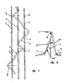
- the two connecting rods are integrally formed with one another, so that a single connecting rod 25 is used.
- the connecting rod 25 is provided with V-shaped regions 4 which have legs 5, 6.
- the legs 5, 6 of the connecting rod 25 run in contrast to the legs of the connecting rods 3 not in a single plane, but alternately in two planes inclined to each other by the angle a.
- the one-piece connecting rod is thus zigzag in two directions, as can be seen from FIGS. 4 and 7.
- There is a change of direction in the area of the upper chord 7 such that a leg 5, 6 extending from one of the lower chords 19, 21 to the upper chord 7 is then no longer returned to the same lower chord 19, 21 but to the other lower flange 21, 19 runs.
- upper and lower reversal regions 11, 13 between legs 5, 6 are bent over in order to form upper and lower loops 15, 17 for good anchoring of the lattice girders 1.
- the upper loops 15 each have legs 5, 6, one of which is connected to the lower flange 19 and the other to the lower flange 21.
- the connecting rod 25 is connected to the upper chord 7 and the lower chords 19, 21, for example by welding.
- the manufacture of the lattice girder according to the second exemplary embodiment is simplified because only a single connecting rod 25 is assigned to the upper chord 7 or the lower chords 19, 21.
Landscapes
- Engineering & Computer Science (AREA)
- Architecture (AREA)
- Civil Engineering (AREA)
- Structural Engineering (AREA)
- Rod-Shaped Construction Members (AREA)
Applications Claiming Priority (4)
| Application Number | Priority Date | Filing Date | Title |
|---|---|---|---|
| DE19904022244 DE4022244A1 (de) | 1990-07-12 | 1990-07-12 | Gittertraeger zur halterung zweier beabstandeter bewehrungsnetze |
| DE4022244 | 1990-07-12 | ||
| DE19904036293 DE4036293A1 (de) | 1990-11-14 | 1990-11-14 | Gittertraeger |
| DE4036293 | 1990-11-14 |
Publications (1)
| Publication Number | Publication Date |
|---|---|
| EP0465777A1 true EP0465777A1 (fr) | 1992-01-15 |
Family
ID=25894945
Family Applications (2)
| Application Number | Title | Priority Date | Filing Date |
|---|---|---|---|
| EP91106473A Expired - Lifetime EP0465776B1 (fr) | 1990-07-12 | 1991-04-23 | Poutre en treillis |
| EP91106474A Withdrawn EP0465777A1 (fr) | 1990-07-12 | 1991-04-23 | Poutre en treillis |
Family Applications Before (1)
| Application Number | Title | Priority Date | Filing Date |
|---|---|---|---|
| EP91106473A Expired - Lifetime EP0465776B1 (fr) | 1990-07-12 | 1991-04-23 | Poutre en treillis |
Country Status (3)
| Country | Link |
|---|---|
| EP (2) | EP0465776B1 (fr) |
| AT (1) | ATE109238T1 (fr) |
| DE (1) | DE59102324D1 (fr) |
Cited By (5)
| Publication number | Priority date | Publication date | Assignee | Title |
|---|---|---|---|---|
| WO1993015287A1 (fr) * | 1992-01-31 | 1993-08-05 | Franz Bucher | Poutre en treillis |
| AU700414B1 (en) * | 1998-07-21 | 1999-01-07 | Haedong Metal Co., Ltd. | Deck panel for reinforced concrete slabs |
| EP1101879A1 (fr) * | 1999-11-19 | 2001-05-23 | A.F.B.A. | Poutre en treillis |
| CZ298232B6 (cs) * | 1999-07-19 | 2007-08-01 | Filigran Traegersysteme Gmbh & Co.Kg | Prubezná výztuz pro ploché stropní konstrukce |
| CN111719774A (zh) * | 2020-07-15 | 2020-09-29 | 广东海洋大学 | 预制装配式拓补受弯构件及其制作方法 |
Families Citing this family (1)
| Publication number | Priority date | Publication date | Assignee | Title |
|---|---|---|---|---|
| FR2792350B3 (fr) | 1999-04-15 | 2001-03-09 | A F B A | Poutre en treillis - chevetre auto-coffrant et linteau coffrant mettant en oeuvre une telle poutre |
Citations (5)
| Publication number | Priority date | Publication date | Assignee | Title |
|---|---|---|---|---|
| FR1234326A (fr) * | 1958-06-11 | 1960-10-17 | Bottiger & Co | Poutre soudée pour le montage de planchers et procédé pour sa fabrication |
| DE1126112B (de) * | 1955-02-03 | 1962-03-22 | Max Gessner Dipl Ing Dipl Ing | Zickzackbuegel fuer Stahlbeton- oder Spannbetontraeger |
| CH410353A (de) * | 1964-01-15 | 1966-03-31 | Zander Siegfried | Geschweisster Bewehrungskorb mit einer Schalungshaut |
| DE1559463A1 (de) * | 1965-10-11 | 1970-06-18 | Avi Alpenlaendische Vered | Untergurtloser Fachwerktraeger |
| DE2311593A1 (de) * | 1973-03-08 | 1974-09-19 | Georg Hubmann | Bewehrungselement |
Family Cites Families (6)
| Publication number | Priority date | Publication date | Assignee | Title |
|---|---|---|---|---|
| BE542127A (fr) * | 1954-10-19 | |||
| DE1211781B (de) * | 1958-01-07 | 1966-03-03 | Herbert Ainedter Dipl Ing | Fachwerktraeger zum Bewehren von Betonbauteilen |
| FR1461660A (fr) * | 1965-10-28 | 1966-02-25 | A V I Alpenlandische Veredelun | Poutre à treillis sans membrure inférieure |
| DE1938011A1 (de) * | 1969-07-26 | 1971-01-28 | Paul Merrettig | Raeumlicher Traeger fuer Stahlbetonrippendecken |
| AT322800B (de) * | 1971-04-23 | 1975-06-10 | Hubmann Georg | Bewehrungselement sowie dessen anwendung |
| AT373012B (de) * | 1980-12-29 | 1983-12-12 | Bucher Franz | Gittertraeger fuer die herstellung von stahlbetondecken |
-
1991
- 1991-04-23 AT AT91106473T patent/ATE109238T1/de not_active Application Discontinuation
- 1991-04-23 DE DE59102324T patent/DE59102324D1/de not_active Expired - Fee Related
- 1991-04-23 EP EP91106473A patent/EP0465776B1/fr not_active Expired - Lifetime
- 1991-04-23 EP EP91106474A patent/EP0465777A1/fr not_active Withdrawn
Patent Citations (5)
| Publication number | Priority date | Publication date | Assignee | Title |
|---|---|---|---|---|
| DE1126112B (de) * | 1955-02-03 | 1962-03-22 | Max Gessner Dipl Ing Dipl Ing | Zickzackbuegel fuer Stahlbeton- oder Spannbetontraeger |
| FR1234326A (fr) * | 1958-06-11 | 1960-10-17 | Bottiger & Co | Poutre soudée pour le montage de planchers et procédé pour sa fabrication |
| CH410353A (de) * | 1964-01-15 | 1966-03-31 | Zander Siegfried | Geschweisster Bewehrungskorb mit einer Schalungshaut |
| DE1559463A1 (de) * | 1965-10-11 | 1970-06-18 | Avi Alpenlaendische Vered | Untergurtloser Fachwerktraeger |
| DE2311593A1 (de) * | 1973-03-08 | 1974-09-19 | Georg Hubmann | Bewehrungselement |
Cited By (6)
| Publication number | Priority date | Publication date | Assignee | Title |
|---|---|---|---|---|
| WO1993015287A1 (fr) * | 1992-01-31 | 1993-08-05 | Franz Bucher | Poutre en treillis |
| AU700414B1 (en) * | 1998-07-21 | 1999-01-07 | Haedong Metal Co., Ltd. | Deck panel for reinforced concrete slabs |
| CZ298232B6 (cs) * | 1999-07-19 | 2007-08-01 | Filigran Traegersysteme Gmbh & Co.Kg | Prubezná výztuz pro ploché stropní konstrukce |
| EP1101879A1 (fr) * | 1999-11-19 | 2001-05-23 | A.F.B.A. | Poutre en treillis |
| FR2801330A1 (fr) * | 1999-11-19 | 2001-05-25 | A F B A | Poutre en treillis |
| CN111719774A (zh) * | 2020-07-15 | 2020-09-29 | 广东海洋大学 | 预制装配式拓补受弯构件及其制作方法 |
Also Published As
| Publication number | Publication date |
|---|---|
| EP0465776B1 (fr) | 1994-07-27 |
| ATE109238T1 (de) | 1994-08-15 |
| DE59102324D1 (de) | 1994-09-01 |
| EP0465776A1 (fr) | 1992-01-15 |
Similar Documents
| Publication | Publication Date | Title |
|---|---|---|
| DE3990874C2 (de) | Selbsttragendes, miteinander zu verbindendes Schalungselement zum Gießen von Wandkonstruktionen | |
| AT396274B (de) | Bewehrungskoerper fuer eine deckenplatte | |
| DE68926671T2 (de) | Betonschalungssystem | |
| DE9407358U1 (de) | Element zur Anwendung bei der Herstellung armierter, mit Aushöhlungen versehener Betonkonstruktionen und Füllkörper zur Herstellung eines derartigen Elements | |
| EP1718814A1 (fr) | Procede et agent auxiliaire pour produire des elements en beton, en particulier des produits semi-finis en beton et/ou des revetements en beton, et agent auxiliaire pour produire des revetements en beton | |
| EP0388692A1 (fr) | Elément isolé de raccordement pour plaque en porte-à-faux | |
| EP0023042B1 (fr) | Elément de plancher préfabriqué pour planchers de bâtiments | |
| EP0519146B1 (fr) | Coffrage d'about | |
| EP0465777A1 (fr) | Poutre en treillis | |
| EP0299226B1 (fr) | Coffrage pour la réalisation d'éléments de construction en béton | |
| DE3210680C2 (fr) | ||
| DE4036293A1 (de) | Gittertraeger | |
| DE60007824T2 (de) | Gitterträger | |
| DE2905165A1 (de) | Raeumlicher baukoerper | |
| EP1113115A2 (fr) | Douille et broche pour la connection d'éléments de construction adjacents | |
| DE9018094U1 (de) | Vorgefertigte Stahlbeton-Doppelschale | |
| EP0848119B1 (fr) | Raccordement d'armature | |
| EP2175079B1 (fr) | Procédé de formation d'une armature d'angle résistante à la flexion pour la construction en béton armé, élément d'armature et armature d'angle résistante à la flexion | |
| DE1804657A1 (de) | Verfahren zur Herstellung von Beton- bzw.Stahlbetonwaenden und nach diesem Verfahren hergestellte Beton- bzw.Stahlbetonwand | |
| AT402419B (de) | Gitterträger | |
| EP0133617B1 (fr) | Armature pour constructions en béton armé | |
| EP0566539A1 (fr) | Armature pour maçonnerie | |
| DE1559530A1 (de) | Wandkonstruktion,insbesondere Bewehrungseinheit | |
| CH662600A5 (de) | Verfahren zur herstellung eines armierten mauerwerkes sowie mauerstein und armierungsbuegel zur ausfuehrung des verfahrens. | |
| AT380506B (de) | Vorgefertigtes verlorenes schalungselement |
Legal Events
| Date | Code | Title | Description |
|---|---|---|---|
| PUAI | Public reference made under article 153(3) epc to a published international application that has entered the european phase |
Free format text: ORIGINAL CODE: 0009012 |
|
| AK | Designated contracting states |
Kind code of ref document: A1 Designated state(s): AT BE DE FR SE |
|
| STAA | Information on the status of an ep patent application or granted ep patent |
Free format text: STATUS: THE APPLICATION IS DEEMED TO BE WITHDRAWN |
|
| 18D | Application deemed to be withdrawn |
Effective date: 19920716 |