EP0465776B1 - Poutre en treillis - Google Patents
Poutre en treillis Download PDFInfo
- Publication number
- EP0465776B1 EP0465776B1 EP91106473A EP91106473A EP0465776B1 EP 0465776 B1 EP0465776 B1 EP 0465776B1 EP 91106473 A EP91106473 A EP 91106473A EP 91106473 A EP91106473 A EP 91106473A EP 0465776 B1 EP0465776 B1 EP 0465776B1
- Authority
- EP
- European Patent Office
- Prior art keywords
- loops
- lattice girder
- connecting bar
- chord member
- lattice
- Prior art date
- Legal status (The legal status is an assumption and is not a legal conclusion. Google has not performed a legal analysis and makes no representation as to the accuracy of the status listed.)
- Expired - Lifetime
Links
Images




Classifications
-
- E—FIXED CONSTRUCTIONS
- E04—BUILDING
- E04C—STRUCTURAL ELEMENTS; BUILDING MATERIALS
- E04C5/00—Reinforcing elements, e.g. for concrete; Auxiliary elements therefor
- E04C5/01—Reinforcing elements of metal, e.g. with non-structural coatings
- E04C5/06—Reinforcing elements of metal, e.g. with non-structural coatings of high bending resistance, i.e. of essentially three-dimensional [3D] extent, e.g. lattice girders
- E04C5/065—Light-weight girders, e.g. with precast parts
Definitions
- the invention relates to a lattice girder with a zigzag-shaped continuous connecting rod with essentially V-shaped sections arranged in a row, the legs of which are each connected via upper and lower rounded reversal areas, which are connected to an upper and a lower flange and are bent at reversal areas, to form loops.
- the invention further relates to the use of such a lattice girder.
- Lattice girders of this type are used, for example, to hold a lower and an upper reinforcement mesh arranged at a distance therefrom, each with transverse and longitudinal bars arranged at a distance from one another; the loops are designed for connection to a reinforcement network.
- the loops can also be used to rest on formwork surfaces, reinforcement nets or the like, without the loops being connected to the reinforcement net.
- a known lattice girder of this type (DE-OS 38 19 473) for holding prefabricated reinforcement mats, loops are formed both in the area of the upper chord and the lower chord, each of which extends from the connecting rod in the same direction.
- the known lattice girder which is essentially designed as a flat component, is arranged within a lower and an upper reinforcement mat so that the lower and upper loops each one Grip the crossbar of the lower or upper structural steel mat.
- the lower chord of the lattice girder which is arranged essentially in a vertical plane, rests on longitudinal bars of the lower structural steel mat, while longitudinal bars of the upper structural steel mat rest on the upper chord of the lattice girder; this arrangement results in a predetermined distance between the lower and the upper structural steel mat.
- the known lattice girder does not have its own stability, it is necessary for it to be assigned support elements for an arrangement between two structural steel mats, which have to be connected obliquely to the lattice girder via hook-like sections on the one hand with the lattice girder and on the other hand with a crossbar of the lower reinforcement mat.
- the arrangement of the known lattice girder between two reinforcement mats requires a relatively large amount of effort because the lattice girder must first be arranged and held in this position until the required stability is subsequently achieved by the arrangement of the support elements.
- a corresponding bracket via an additional support element is also provided for a flat truss formed as a lattice girder (DE-OS 22 34 941).
- a flat truss formed as a lattice girder (DE-OS 22 34 941).
- diagonal struts are arranged between an upper and lower flange and provided with hook-shaped bends.
- the invention has for its object to develop a lattice girder of the type mentioned so that it is easy to manufacture and assemble and that it has a high level of stability.
- the lattice girder is used to hold reinforcement meshes, two reinforcement meshes should be able to be held securely at a predeterminable distance from one another without the use of additional support elements, the reinforcement meshes to be held both by prefabricated reinforcement meshes, such as reinforcing steel meshes or the like, and by correspondingly assigned individual bars can be formed as reinforcement elements.
- the invention When the lattice girder is used to reinforce concrete slabs or the like, the invention further provides a high level of stability and a high level of security against the lattice girder being torn out of a concrete slab or the like.
- the objects on which the invention is based are achieved according to the invention in the case of a lattice girder of the generic type in that the loops are formed only in the upper or lower reversal regions of the connecting rod, a first connecting rod with a lower flange arranged above its loops, a second identically designed one and with the upper flange connected connecting rod is assigned so that its loops are arranged above the top chord, that both connecting rods each run at an angle of inclination with respect to a central plane, and that the loops of both connecting rods are arranged in the same direction, with those of the first Extend connecting rod in the direction facing away from the second connecting rod.
- two connecting rods which are of identical design and each have loops on only one side, that is to say only in the upper or lower reversal regions, results in simple manufacture, in which two connecting rods of identical design are arranged with the loops arranged appropriately can be connected to each other via a common top chord.
- the two inclination angles can be made the same.
- the lattice girder according to the invention can thus be used simply and safely for reinforcing concrete slabs or the like.
- the loops provide sufficient stability when placed on a formwork surface, a reinforcement net or the like and prevent the lattice girder from being torn out after being embedded in concrete.
- the lattice girder is stable without the need for additional support elements, in that the second connecting rod is supported on a support or formwork level.
- an upper reinforcement network can be arranged so that one of the cross bars from the loops of the second connecting rod located above are encompassed from above; this results in a support for the upper reinforcement network in that its longitudinal bars rest on the top chord of the lattice girder.
- the lattice girder according to the invention thus enables simple and quick assignment of two reinforcement networks, which are formed, for example, from prefabricated reinforcing steel meshes or assigned individual bars, and if reinforcement networks assigned to one another at such a distance are exposed to a strong vibration load or have to be transported in a connected manner before their further processing, it is for a secure connection, it is only necessary that a connection of the upper and possibly the lower reinforcement network to the lattice girder is created at some points, for example by means of wire rod or by welding.
- Such a connection, which is to be established as required can be carried out considerably more easily after the actual installation than an arrangement of a support element to be carried out between two adjacent reinforcement mats in the course of the installation of a known support element.
- lattice girders of this type can be stacked one above the other, as a result of which they can be easily transported, stored and made available for assembly in stacks.
- the first and the second connecting rod are assigned to one another in the longitudinal direction of the lattice girder in such a way that their V-shaped sections are each arranged essentially symmetrically to one another. The symmetry arises with respect to a vertical center line of the V-shaped areas.
- first and the second connecting rod in the longitudinal direction of the lattice girder is assigned to one another in such a way that their V-shaped regions are each offset from one another. This means that reversal areas with and without loops of the first and second connecting rods lie essentially vertically opposite one another in the height direction of the lattice girder. This simplifies the manufacture of the lattice girder, for example, in that the connecting rods can be easily welded to the upper and lower chords.
- the second connecting rod is arranged in such a way that its loops for holding prefabricated reinforcement mats essentially connect directly to the lower flange. For a connection to the reinforcement mats, loops only have to be inserted into reinforcement mats in order to come into engagement with an associated cross bar.
- loops can be formed on each of the reversal areas arranged on one side of a connecting rod; however, they can also be arranged at a greater distance from one another, in which case a corresponding number of reversing areas, which have no loops, are then arranged between two adjacent loops.
- the apex sections of reversal areas present between loops are advantageously at the same height as corner areas over which the loops extend from the legs.
- the lower flange is arranged substantially directly above the loops of the first connecting rod and is fastened to the latter in order to form a stop for a transverse rod of a lower reinforcement network.
- first connecting rod is connected to the upper chord via apex sections of reversal regions and the second connecting rod is connected to the corner regions over which the loops extend from the legs. This leads to an easy to manufacture, stable shape of the lattice girder.
- the second connecting rod is arranged in such a way that its loops for holding individually assigned individual rods of a reinforcement network run above the upper chord at a predeterminable distance.
- An arrangement of such lattice girders can be used to form a lower or an upper reinforcement network by assigning transverse and longitudinal bars to the lattice girder and each other as reinforcement elements which are not connected to one another beforehand. Due to the distance between the top chord and loops, an intermediate space for receiving longitudinal bars and at least one transverse bar resting on it is formed. The longitudinal bars in turn lie on lattice girders arranged adjacent to one another on the upper chords.
- the lower flange can advantageously be arranged at a predeterminable distance above the loops of the first connecting rod and connected to it. In this way, an intermediate space for receiving at least one transverse rod and of longitudinal rods resting thereon is formed in a simple manner.
- the crossbar lies on the loops of the first connecting bar.
- the second connecting rod is assigned a second lower flange, which is at substantially the same distance from the upper flange as the lower flange of the first connecting rod.
- the second lower flange can be attached to the reverse side of the second connecting rod on the side facing away from the first connecting rod. This arrangement of the second lower flange is easy to manufacture on the one hand and on the other hand leads to good support and a relatively high rigidity for the lattice girder.
- the connecting rods can be welded to the assigned belts.
- the loops each run at an angle of inclination upwards with respect to a horizontal plane running perpendicular to the central plane or a support plane for the lattice girder.
- This arrangement of the loops results on the one hand in a simple insertion of a lower reinforcement mat in such a way that a cross bar of this reinforcement mat is encompassed by loops.
- transverse bars assigned to the loops come out of engagement with them.
- spacers are advantageously assigned to at least some of the loops at the bottom and / or at the top of the first and / or second connecting rod in order to arrange the lattice girder at a distance from a support or formwork plane.
- the assignment of one or more such spacers enables, for example, a predeterminable positional arrangement of a lattice girder inserted into a lower reinforcement network.
- the arrangement of spacers on loops located below contributes to a substantial increase in the stability of a lattice girder inserted into a lower reinforcement network.
- load application points or lines for a crossbar of the lower reinforcement network can be achieved in the area of a lower loop, which run in such a way that weight forces introduced in the lower reinforcement network cannot lead to a tilting moment regarding the lattice girder. This increases the stability of a lattice girder inserted in a lower reinforcement network in a simple manner.
- the arrangement of spacers also advantageously results in the lower and / or upper loops and thus the lower and / or upper reinforcement mesh carried by them being arranged at a distance from a support level or a formwork level.
- the spacers can be formed by rod elements welded to loops. This results in a particularly simple manufacture and arrangement of the spacers on the lattice girder.
- the Rod elements can be made of stainless steel.
- spacers which may not be completely covered with concrete, from becoming unsusceptible to rust formation in edge regions.
- spacers can be extended in the direction facing away from the circuit plane.
- Spacers can also be formed in a particularly simple manner by bent end portions of the loops. For corrosion protection, these end sections can be provided in a simple manner, for example by dipping, with a protective coating, for example made of plastic.
- Spacers can also be formed in a simple manner by plastic elements that can be connected to the lattice girder. Such plastic elements are easy to manufacture and can be connected via a clamp connection, for example with a loop or a lower chord.
- the plastic elements can have a receptacle for part of a loop. However, they can also advantageously be designed in the form of a circular disk with a slot-shaped receptacle for a section of a loop or a lower chord.
- Lattice girders according to the invention according to one or more of the features mentioned above can be used according to the invention for holding a lower and / or an upper reinforcement mesh arranged at a distance therefrom, each with spaced transverse and longitudinal bars. This results in a simple connection or assembly with the loops the upper and / or the lower reinforcement network.
- Lattice girders according to the invention according to one or more of the above-mentioned features can be used according to the invention for reinforcing concrete slabs or the like.
- the loops result in a support on a formwork surface, a reinforcement network or the like not connected to the lattice girders, with a high degree of stability, and tearing out of a concrete part in which the loops are embedded is avoided.
- the first exemplary embodiment shown in FIGS. 1 to 4 for a lattice girder according to the invention, generally designated 1, relates to a lattice girder for holding prefabricated reinforcement meshes, such as reinforcing steel meshes.
- the lattice girder 1 has a first connecting rod 3 and a second connecting rod 5.
- the two connecting rods 3, 5 are of identical design and they run continuously in a zigzag pattern over the entire length of the lattice girder 1. They are formed, for example, from a round steel bar with a diameter of, for example, 5 mm to 6 mm. Since the two connecting rods 3, 5 are of identical design, only the first connecting rod 3 is referred to below with regard to the shape of the connecting rods. This description applies accordingly to the second connecting rod 5.
- the first connecting rod 3 has a zigzag shape, with V-shaped sections with legs 11 adjoining each other via reversing regions 7, so that reversing regions are present on one side of the connecting rods 3, 5 to form loops 13 the plane of the legs 11 and the reversal areas 7 remaining on the other side.
- the not yet bent reversal areas 7 ' by the bending of which the loops 13 are formed, are shown in Fig. 1 by dash-dotted lines; they are rounded off with a radius R corresponding to the reversal areas 7.
- rounded corner regions 15 are formed by the bending over which each leg 11 merges into a part of a loop 13.
- the two connecting rods 3, 5 are connected to one another via a common upper flange 17.
- the upper chord 17 extends in the longitudinal direction of the two connecting rods 3, 5 and essentially ends with them.
- the two connecting rods 3, 5 are assigned to one another in such a way that they each extend at an angle ⁇ relative to a common central plane 19;
- the upper chord 17, which is formed from a round rod with, for example, 6 mm to 8 mm in diameter, is arranged symmetrically with respect to the central plane 19. According to the cross section shown in FIG.
- legs 11 of the two connecting rods 3, 5, starting from the upper flange 17, run essentially in a V-shape with respect to one another.
- the two connecting rods 3, 5 are also assigned to one another such that a reversal area 7 is assigned to a loop 13 in the center.
- the two connecting rods 3, 5 are assigned to one another in the longitudinal direction of the lattice girder 1 so that their V-shaped regions each run symmetrically to one another.
- a plane of symmetry 20 results from the center lines of the V-shaped sections of the two connecting rods 3, 5, which are arranged substantially congruently with one another.
- the two connecting rods 3, 5 are also assigned to one another in such a way that the first connecting rod 3 with loops 13 located below is arranged, the loops 13 extending in a direction facing away from the second connecting rod 5.
- the second connecting rod 5 is in one order 180 ° rotated position so that its loops 13 are on top.
- the loops 13 of the second connecting rod 5 are arranged above the upper flange 17 in the same direction as the loops 13 of the first connecting rod 3.
- the two connecting rods 3, 5 are connected to the upper flange 17, for example by welding. However, it can also be advantageous for a connection to be established by soldering or gluing.
- first and a second connecting rod 3, 5, each of which is connected to one another via a common upper chord 17, results in a lattice girder 1 with sufficient stability.
- the lattice girder 1 according to the invention is easy to manufacture due to the use of connecting rods 3, 5 of the same design and it has a high level of stability.
- the lattice girders 1 according to the invention can be stacked on top of one another for transport, storage or provision for assembly. This facilitates handling before or for assembly and, as described below, the lattice girder 1 according to the invention can also be inserted in a simple manner between a lower and an upper reinforcement mat 25, 31. 4, the lattice girder 1 is first connected to the lower reinforcement mat 25 in such a way that the loops 13 of the first connecting rod 3 come to lie below a transverse rod 27 of the lower reinforcement mat 25.
- the lower flange 21 of the first connecting rod 3 results in a stop for the associated transverse rod 27 of the lower reinforcement mat 25. This results in a simple manner, without the need for subsequent adjustment, during the connection of the lattice girder 1 to the lower reinforcement mat 25 sufficiently precise positional arrangement of the lattice girder 1.
- an upper reinforcement mat 31 to be assigned to the lower reinforcement mat 25 at a predeterminable distance can be assigned to the lattice girder 1.
- first longitudinal bars 33 of the upper reinforcement mat 31 the top chords 17 of the lattice girders 1 are placed.
- the upper reinforcement mat 31 is pushed towards the lattice girder 1 in such a way that the loops 13 of every second connecting rod 5 come to lie above an associated transverse rod 35 of the upper reinforcement mat 31.
- the lattice girder 1 according to the invention is thus installed between a lower one and an upper reinforcement mat 25, 31 completed. Both reinforcement mats 25, 31 are safely arranged at a distance from one another which can be predetermined via the height of the lattice girder 1.
- the cross and longitudinal bars of the reinforcement mats 25, 31, can be arranged so that they are each within the outermost sides of the loops 13, the distance between formwork levels, and thus the wall thickness of the concrete parts to be produced, regardless of the cross sections of the Cross and longitudinal bars and their dimensional accuracy.
- the stability of the lattice girder 1 according to the invention and its high dimensional stability contribute to the safe arrangement of the reinforcement mats 25, 31.
- a connection between the cross bar 35 and the lattice girder 1 can be created, for example, via the arrangement of crimped wires, if the mutually associated reinforcement mats 25, 31 are to be transported in this state, or are subjected to a strong vibration load.
- the lower reinforcement mat 25 can also be connected via longitudinal bars 29 to the lower chord 23 via solder wire or the like.
- each of the loops 13 of the first and the second connecting rod 3, 5 spacers 37 are provided.
- the arrangement of spacers 37 leads to the lattice girder 1 being arranged at a predeterminable distance from a lower or upper formwork level 39.
- the lower reinforcement mat 25 resting thereon is also raised and thus takes up a distance from the support or formwork plane 39 on which the spacers 37 are supported.
- This has the advantage that after filling or pouring with a concrete, the lower reinforcement mat 25 together with the associated loops 13 is arranged further away from an outer surface within a component formed in this way. This results in a good anchoring of the lower reinforcement mat 25 within such a component.
- the upper reinforcement mat 31 which can also be held at a distance from an upper formwork level by means of spacers 37 with the lattice girder 1.
- the arrangement of spacers 37 on lower loops 13 also advantageously results in the assembly of a lattice girder 1 that, after a crossbar 27 of the lower reinforcement mat rests on the loops 13 of the first connecting rod 3, through the weight of the lower reinforcement mat 25th resulting weight force no tilting moment can be formed. Such a tilting moment could otherwise lead to the stability of the lattice girder 1 being impaired.
- the spacers 37 can be formed in one piece in a simple manner from a plastic element with a support web 41 and a receptacle 43 running essentially perpendicularly to it, for part of a loop 13. But it can spacers in the form of a circular disk, for example in one piece, can also be produced from a plastic in a manner not shown.
- the plastic elements can be provided with a slot-shaped receptacle for a section of a loop 13 or a lower chord 21.
- the slot-shaped receptacle like the receptacle 43 described above for part of a loop 13, can be provided, for example, with a detent for a secure connection to the lattice girder 1.
- a spacer can also be formed in a manner not shown simply by connecting a rod element corresponding to the support web 41, for example made of stainless steel, to a loop 13 by welding, or by bending an end region of loops 13 accordingly.
- a corrosion protection coating can be applied to the spacer.
- spacers 37 made of stainless steel or of a plastic element likewise means that end regions of the spacers 37, which can be arranged directly adjacent to an outer wall of this concrete part after the completion of a concrete part, do not lead to rust formation on the support plane 39 or formwork levels tend.
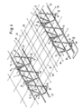
- the two connecting rods 3, 5 are identical to the first exemplary embodiment and are therefore of identical design. You are also in accordance with the first embodiment in the longitudinal direction of the lattice girder 1 'arranged so that the V-shaped portions of the two connecting rods 3, 5 are substantially symmetrical to each other. In contrast to the first exemplary embodiment, they are arranged in such a way that the loops 13 on the top of the second connecting rod 5 are at a distance h from the upper flange 17.
- the loops 13 of the first connecting rod 3 lying at the bottom are at a distance h from the lower flange 21 connected to the first connecting rod 3.
- the lower flange 23 connected to the second connecting rod 5 is connected to the second connecting rod 5 at reversal areas 7 in accordance with the first exemplary embodiment.
- an intermediate space is formed between the loops 13 at the top and the upper chord 17 and accordingly between the loops 13 and the lower chord 21 at the bottom, in which individual bars can be used as longitudinal and transverse bars to form a reinforcement network.
- cross bars 53 and longitudinal bars 55 are first arranged in a corresponding manner on a formwork level 39.
- first upper longitudinal bars 59 are arranged so that they rest on the upper chords 17.
- the longitudinal bars 59 in turn form a support for upper transverse bars 61, each of which rests on the longitudinal bars 59 in a region below loops 13.
- the loops 13 of the lattice girders 1 'located below are assigned spacers 37 formed from plastic elements in order to hold the lattice girders 1' and with them the lower reinforcement network 51 at a predeterminable distance from the support surface or formwork level 39.
- spacers 37 can also be assigned to the loops 13 at the top for a distance from an upper formwork level.
- the spacers 37 are designed in accordance with those described in connection with the first exemplary embodiment.
- the third embodiment shown in FIGS. 6 to 8 of a lattice support designated overall by 1 classroom differs from the lattice support 1, 1 'according to the first and the second embodiment in that the two connecting rods 3, 5 designed according to the first and second embodiment , as can be seen from FIGS. 6 and 8, are arranged offset to one another in the longitudinal direction of the lattice girder 1 ⁇ .
- the V-shaped sections formed on each of the two connecting rods 3, 5, each with two legs 11, are arranged in such a way that that V-shaped sections of the connecting rods 3, 5 are each offset from one another. As can be seen from FIG.
- an upwardly open V-shaped section of the connecting rod 3 is opposite a downwardly open V-shaped section of the second connecting rod 5 and vice versa.
- the V-shaped sections of the two connecting rods 3, 5 are, as can be seen from FIG. 6, essentially arranged such that their center lines lie in the plane of symmetry 20 (see FIG. 1).
- the remaining parts of the lattice girder 1 ⁇ correspond to those of the first embodiment. They are therefore provided with the same reference numerals and reference is made to that of the first exemplary embodiment for a description.
- the loops 13 can be arranged opposite each lower and upper belt 21, 23, 17 such that, in a manner not shown, in each case between a loop 13 and an adjacent belt or adjacent belts a distance h (Fig. 5) is present.
- the lattice girders 1, 1 'and 1 ⁇ according to the invention are easy to manufacture and, due to their high level of stability, they can be used simply for holding prefabricated reinforcement mats 25, 31 or reinforcement meshes 51, 57 formed from individual bars.
- the lattice girders 1, 1 ', 1 ⁇ can be held together with the reinforcement mats 25, 31 or reinforcement meshes 51, 57 held by them at a predeterminable distance from formwork levels 39.
- the stability of the lattice girders 1, 1 'and 1 ⁇ according to the invention can be increased in an advantageous manner by the arrangement of spacers 37 so that tilting due to the weight forces of reinforcing meshes is completely excluded is.
- the lattice girders 1, 1 'and 1 ⁇ according to the invention are advantageously suitable for the production of prefabricated concrete parts, such as wall or ceiling elements. Due to their ease of assembly, they are also well suited for the manufacture of reinforcements on buildings on site.
- the lattice girders 1, 1 'and 1 ⁇ according to the invention can also be used advantageously for reinforcing concrete slabs, as described in detail in the more recent German patent application P 40 36 293.0.
- the description section of the more recent application relating to this application is referred to in detail.
- With a suitable design of the loops 13 can be ensured when using the lattice girders 1, 1 ', 1 ⁇ for example for producing double-walled wall elements that loops 13 embedded in wall areas are firmly anchored and do not tear out.
- the lattice girders 1, 1 'and 1 ⁇ are only placed at a suitable distance from each other on a formwork surface or on a reinforcement network not connected to the lattice girders. Adequate stability is provided by the installation of a corresponding number of loops 13. Furthermore, if the loops 13 are designed and sized accordingly, after the first wall area has been formed, it can be ensured that the lattice girders 1, 1 have sufficient stability to form a second wall area ', 1 ⁇ with the then arranged at a distance above the formwork first wall area on a formwork surface or the like.
Landscapes
- Engineering & Computer Science (AREA)
- Architecture (AREA)
- Civil Engineering (AREA)
- Structural Engineering (AREA)
- Rod-Shaped Construction Members (AREA)
Claims (15)
- Poutre en treillis comportant une barre de liaison continue en forme de zig-zag, qui possède des sections successives essentiellement en forme de V, dont les branches sont reliées respectivement par l'intermédiaire d'une partie de renvoi arrondie supérieure et d'une partie de renvoi arrondie inférieure, qui est reliée à une membrure supérieure et à une membrure inférieure et est repliée au niveau des éléments de renvoi, pour former des boucles, caractérisée par le fait que les boucles (13) sont formées uniquement au niveau des éléments de renvoi supérieurs ou inférieurs (7) de la barre de liaison (3, 5), et à une première barre de liaison (3) comportant une membrure inférieure (21) disposée au-dessus de sa boucle (13) est associée une seconde barre de liaison (5), qui est agencée de la même manière et est reliée à la membrure (7), de telle sorte que ces boucles (13) sont disposées au-dessus de la membrure supérieure (17), que les deux barres de liaison (3, 5) s'étendent en faisant respectivement un angle d'inclinaison (α) par rapport à un plan médian (19), et que les boucles (13) des deux barres de liaison (3, 5) sont disposées dans le même sens, les boucles de la première barre de liaison (3) s'étendant dans la direction tournée à l'opposé de celle des boucles de la seconde barre de liaison (5).
- Poutre en treillis suivant la revendication 1, caractérisée par le fait que les première et seconde barres de liaison (3, 5) sont associées entre elles dans la direction longitudinale de la poutre en treillis (1, 1′) de telle sorte que leurs sections en forme de V sont disposées respectivement sensiblement symétriquement par rapport à un plan (20) qui est perpendiculaire à la direction longitudinale.
- Poutre en treillis suivant la revendication 1, caractérisée par le fait que les première et seconde barres de liaison (3, 5) sont associées entre elles dans la direction longitudinale de la poutre en treillis (1˝) de telle sorte que leurs sections en forme de V sont disposées en étant réciproquement décalées.
- Poutre en treillis suivant l'une des revendications 1 à 3, caractérisée par le fait que la seconde barre de liaison (5) est disposée de telle sorte que ses boucles (13) se raccordent sensiblement directement à la membrure supérieure (17) pour la fixation de treillis soudés préfabriqués.
- Poutre en treillis suivant l'une des revendications 1 à 4, caractérisée par le fait qu'un ou plusieurs éléments de renvoi (7) sans boucles (13) sont disposés entre des boucles directement voisines (13) d'une barre de liaison (3, 5), de telle sorte que les parties sommitales sont situées sensiblement à la même hauteur que les sections d'angle (15) au-dessus des boucles (13) des branches (11).
- Poutre en treillis suivant l'une des revendications 1 à 5, caractérisée par le fait que la membrure inférieure (21) est disposée sensiblement directement au-dessus des boucles (13) de la première barre de liaison (3) et est fixée à cette barre de manière à former une butée pour une barre transversale (27) d'un réseau inférieur d'armature (25).
- Poutre en treillis suivant l'une des revendications 1 à 6, caractérisée par le fait que la première barre de liaison (3) est reliée par l'intermédiaire de parties sommitales d'éléments de renvoi (4) à la membrure supérieure (17) et que la seconde barre de liaison (5) est reliée à la membrure supérieure (17) par l'intermédiaire des zones d'angle (15), au-dessus desquelles s'étendent les boucles (13) des branches (11).
- Poutre en treillis suivant l'une des revendications 1 à 3, caractérisée par le fait que la seconde barre de liaison (5) est disposée de telle sorte que ses boucles (13) s'étendent de manière à supporter des barres individuelles, qui sont associées individuellement entre elles, d'un réseau d'armature (52, 61), à une distance (h), pouvant être prédéterminée, au-dessus de la membrure supérieure (17).
- Poutre en treillis suivant l'une des revendications 1 à 5, caractérisée par le fait que la membure inférieure (21) est disposée à une distance (h), qui peut être prédéterminée, au-dessus des boucles (13) de la première barre de liaison (3) et est reliée à cette barre.
- Poutre en treillis suivant l'une des revendications 1 à 9, caractérisée par le fait qu'à la seconde barre de liaison (5) est associée une seconde membrure inférieure (23), qui est située essentiellement à la même distance de la membrure supérieure (17), que la membrure inférieure (21) de la première barre de liaison (3).
- Poutre en treillis suivant l'une des revendications 1 à 10, caractérisée par le fait que les boucles (13) s'étendent respectivement sous un angle d'inclinaison dirigé vers le haut par rapport à un plan horizontal (39), qui est perpendiculaire au plan médian (19).
- Poutre en treillis suivant l'une des revendications 1 à 11, caractérisée par le fait qu'au moins à des boucles (13) de la première et/ou de la seconde barre de liaison (3, 5) sont associées des entretoises (37) servant à maintenir une distance entre la poutre en treillis (1) et les réseaux d'armature associés par rapport à au moins un appui ou un plan de coffrage (39).
- Poutre en treillis suivant la revendication 12, caractérisée par le fait qu'au moins une entretoise (37) possède un élément en matière plastique, qui comporte un logement (43) pour une partie d'une boucle (13) ou est réalisé sensiblement en forme de disque circulaire, avec un logement en forme de fente pour une section d'une boucle ou d'une membrure inférieure.
- Utilisation d'une poutre en treillis suivant l'une des revendications 1 à 13 pour retenir un réseau inférieur d'armature et/ou un réseau supérieur d'armature, qui est distant du réseau d'armature inférieur et comportant des barres transversales et des barres longitudinales disposées respectivement à distance, les boucles (13) établissant une liaison avec le réseau d'armature.
- Utilisation d'une poutre en treillis suivant l'une des revendications 1 à 13 pour l'armaturage de plaques en béton ou analogues, un appui par rapport à une surface de coffrage d'un réseau d'armature non relié aux poutres en treillis, ou analogue étant formé par les boucles (13).
Applications Claiming Priority (4)
| Application Number | Priority Date | Filing Date | Title |
|---|---|---|---|
| DE19904022244 DE4022244A1 (de) | 1990-07-12 | 1990-07-12 | Gittertraeger zur halterung zweier beabstandeter bewehrungsnetze |
| DE4022244 | 1990-07-12 | ||
| DE4036293 | 1990-11-14 | ||
| DE19904036293 DE4036293A1 (de) | 1990-11-14 | 1990-11-14 | Gittertraeger |
Publications (2)
| Publication Number | Publication Date |
|---|---|
| EP0465776A1 EP0465776A1 (fr) | 1992-01-15 |
| EP0465776B1 true EP0465776B1 (fr) | 1994-07-27 |
Family
ID=25894945
Family Applications (2)
| Application Number | Title | Priority Date | Filing Date |
|---|---|---|---|
| EP91106473A Expired - Lifetime EP0465776B1 (fr) | 1990-07-12 | 1991-04-23 | Poutre en treillis |
| EP91106474A Withdrawn EP0465777A1 (fr) | 1990-07-12 | 1991-04-23 | Poutre en treillis |
Family Applications After (1)
| Application Number | Title | Priority Date | Filing Date |
|---|---|---|---|
| EP91106474A Withdrawn EP0465777A1 (fr) | 1990-07-12 | 1991-04-23 | Poutre en treillis |
Country Status (3)
| Country | Link |
|---|---|
| EP (2) | EP0465776B1 (fr) |
| AT (1) | ATE109238T1 (fr) |
| DE (1) | DE59102324D1 (fr) |
Families Citing this family (6)
| Publication number | Priority date | Publication date | Assignee | Title |
|---|---|---|---|---|
| ATA16492A (de) * | 1992-01-31 | 1997-06-15 | Bucher Franz | Gitterträger |
| AU700414B1 (en) * | 1998-07-21 | 1999-01-07 | Haedong Metal Co., Ltd. | Deck panel for reinforced concrete slabs |
| FR2792350B3 (fr) | 1999-04-15 | 2001-03-09 | A F B A | Poutre en treillis - chevetre auto-coffrant et linteau coffrant mettant en oeuvre une telle poutre |
| DE29912526U1 (de) * | 1999-07-19 | 1999-09-23 | Filigran Trägersysteme GmbH & Co KG, 31633 Leese | Durchstanzbewehrung für Flachdecken |
| FR2801330B1 (fr) | 1999-11-19 | 2002-05-31 | A F B A | Poutre en treillis |
| CN111719774B (zh) * | 2020-07-15 | 2024-10-29 | 广东海洋大学 | 预制装配式拓补受弯构件及其制作方法 |
Family Cites Families (10)
| Publication number | Priority date | Publication date | Assignee | Title |
|---|---|---|---|---|
| BE542127A (fr) * | 1954-10-19 | |||
| DE1126112B (de) * | 1955-02-03 | 1962-03-22 | Max Gessner Dipl Ing Dipl Ing | Zickzackbuegel fuer Stahlbeton- oder Spannbetontraeger |
| DE1211781B (de) * | 1958-01-07 | 1966-03-03 | Herbert Ainedter Dipl Ing | Fachwerktraeger zum Bewehren von Betonbauteilen |
| FR1234326A (fr) * | 1958-06-11 | 1960-10-17 | Bottiger & Co | Poutre soudée pour le montage de planchers et procédé pour sa fabrication |
| CH410353A (de) * | 1964-01-15 | 1966-03-31 | Zander Siegfried | Geschweisster Bewehrungskorb mit einer Schalungshaut |
| DE1559463C3 (de) * | 1965-10-11 | 1973-10-31 | Avi Alpenlaendische Veredelungs-Industrie Gmbh, Graz, Steiermark (Oesterreich) | Untergurtloser Fachwerkträger |
| FR1461660A (fr) * | 1965-10-28 | 1966-02-25 | A V I Alpenlandische Veredelun | Poutre à treillis sans membrure inférieure |
| DE1938011A1 (de) * | 1969-07-26 | 1971-01-28 | Paul Merrettig | Raeumlicher Traeger fuer Stahlbetonrippendecken |
| AT322800B (de) * | 1971-04-23 | 1975-06-10 | Hubmann Georg | Bewehrungselement sowie dessen anwendung |
| AT373012B (de) * | 1980-12-29 | 1983-12-12 | Bucher Franz | Gittertraeger fuer die herstellung von stahlbetondecken |
-
1991
- 1991-04-23 EP EP91106473A patent/EP0465776B1/fr not_active Expired - Lifetime
- 1991-04-23 EP EP91106474A patent/EP0465777A1/fr not_active Withdrawn
- 1991-04-23 DE DE59102324T patent/DE59102324D1/de not_active Expired - Fee Related
- 1991-04-23 AT AT91106473T patent/ATE109238T1/de not_active Application Discontinuation
Also Published As
| Publication number | Publication date |
|---|---|
| DE59102324D1 (de) | 1994-09-01 |
| EP0465776A1 (fr) | 1992-01-15 |
| ATE109238T1 (de) | 1994-08-15 |
| EP0465777A1 (fr) | 1992-01-15 |
Similar Documents
| Publication | Publication Date | Title |
|---|---|---|
| DE3013710C2 (de) | Vorrichtung zum Verwahren von in einer Betonwand zu verankernden Bewehrungsstäben | |
| EP0131841A2 (fr) | Ancrage pour un panneau stratifié | |
| EP0495334B1 (fr) | Armature de cisaillement pour des plafonds plats | |
| EP0465776A1 (fr) | Poutre en treillis | |
| EP0299226B1 (fr) | Coffrage pour la réalisation d'éléments de construction en béton | |
| DE2114494C3 (de) | Vorgefertigte Stahlbeton-Doppelschale zur Herstellung von Stahlbetonwänden | |
| CH665668A5 (de) | Buegelkorb. | |
| DE69516395T2 (de) | Verankerungsvorrichtung für einen träger | |
| DE2150120A1 (de) | Profilband | |
| EP0361227B1 (fr) | Traverse de chemin de fer en béton précontraint | |
| DE3820476A1 (de) | Verfahren zur montage einer mit ortbeton vergiessbaren deckenschalung | |
| DE2545442C2 (de) | Metall-Abstandhalter | |
| EP0353560A1 (fr) | Espaceur pour armatures de béton | |
| EP1741851B2 (fr) | Grillage d'armature pour béton armé et procédé pour la fabrication d'une armature de paroi | |
| DE60007824T2 (de) | Gitterträger | |
| DE4022244A1 (de) | Gittertraeger zur halterung zweier beabstandeter bewehrungsnetze | |
| EP0350577B1 (fr) | Dispositif de suspension pour profilés à section en C | |
| EP0848118B1 (fr) | Armature de cisaillement pour dalles plates | |
| DE4036293A1 (de) | Gittertraeger | |
| AT409511B (de) | Deckenabschlusselement | |
| DE3120427A1 (de) | Bewehrung fuer die betondeckung von stahlbeton- oder spannbetonteilen | |
| DE4228968A1 (de) | Balken, verfahren zu dessen herstellung, verfahren und vorrichtung zum verbinden solcher balken | |
| DE3044330A1 (de) | Traegermatte fuer heizelemente einer fussbodenheizung | |
| DE3209335A1 (de) | Verbunddecke aus stahl und beton sowie verstrebungsbalken | |
| CH666313A5 (de) | Abstandhaltevorrichtung fuer stahlbeton-konstruktionen. |
Legal Events
| Date | Code | Title | Description |
|---|---|---|---|
| PUAI | Public reference made under article 153(3) epc to a published international application that has entered the european phase |
Free format text: ORIGINAL CODE: 0009012 |
|
| AK | Designated contracting states |
Kind code of ref document: A1 Designated state(s): AT BE DE FR SE |
|
| 17P | Request for examination filed |
Effective date: 19920703 |
|
| 17Q | First examination report despatched |
Effective date: 19930727 |
|
| GRAA | (expected) grant |
Free format text: ORIGINAL CODE: 0009210 |
|
| AK | Designated contracting states |
Kind code of ref document: B1 Designated state(s): AT BE DE FR SE |
|
| REF | Corresponds to: |
Ref document number: 109238 Country of ref document: AT Date of ref document: 19940815 Kind code of ref document: T |
|
| REF | Corresponds to: |
Ref document number: 59102324 Country of ref document: DE Date of ref document: 19940901 |
|
| PG25 | Lapsed in a contracting state [announced via postgrant information from national office to epo] |
Ref country code: SE Effective date: 19941027 |
|
| ET | Fr: translation filed | ||
| PLBE | No opposition filed within time limit |
Free format text: ORIGINAL CODE: 0009261 |
|
| STAA | Information on the status of an ep patent application or granted ep patent |
Free format text: STATUS: NO OPPOSITION FILED WITHIN TIME LIMIT |
|
| 26N | No opposition filed | ||
| PGFP | Annual fee paid to national office [announced via postgrant information from national office to epo] |
Ref country code: AT Payment date: 20020419 Year of fee payment: 12 |
|
| PGFP | Annual fee paid to national office [announced via postgrant information from national office to epo] |
Ref country code: DE Payment date: 20020429 Year of fee payment: 12 |
|
| PGFP | Annual fee paid to national office [announced via postgrant information from national office to epo] |
Ref country code: FR Payment date: 20030417 Year of fee payment: 13 |
|
| PGFP | Annual fee paid to national office [announced via postgrant information from national office to epo] |
Ref country code: BE Payment date: 20030425 Year of fee payment: 13 |
|
| PG25 | Lapsed in a contracting state [announced via postgrant information from national office to epo] |
Ref country code: AT Free format text: LAPSE BECAUSE OF THE APPLICANT RENOUNCES Effective date: 20030430 |
|
| PG25 | Lapsed in a contracting state [announced via postgrant information from national office to epo] |
Ref country code: DE Free format text: LAPSE BECAUSE OF NON-PAYMENT OF DUE FEES Effective date: 20031101 |
|
| PG25 | Lapsed in a contracting state [announced via postgrant information from national office to epo] |
Ref country code: BE Free format text: LAPSE BECAUSE OF NON-PAYMENT OF DUE FEES Effective date: 20040430 |
|
| BERE | Be: lapsed |
Owner name: *BADISCHE DRAHTWERKE G.M.B.H. Effective date: 20040430 |
|
| PG25 | Lapsed in a contracting state [announced via postgrant information from national office to epo] |
Ref country code: FR Free format text: LAPSE BECAUSE OF NON-PAYMENT OF DUE FEES Effective date: 20041231 |
|
| REG | Reference to a national code |
Ref country code: FR Ref legal event code: ST |