EP0465788A1 - Cadre pour portes et fenêtres comprenant des membres profilés - Google Patents
Cadre pour portes et fenêtres comprenant des membres profilés Download PDFInfo
- Publication number
- EP0465788A1 EP0465788A1 EP91107251A EP91107251A EP0465788A1 EP 0465788 A1 EP0465788 A1 EP 0465788A1 EP 91107251 A EP91107251 A EP 91107251A EP 91107251 A EP91107251 A EP 91107251A EP 0465788 A1 EP0465788 A1 EP 0465788A1
- Authority
- EP
- European Patent Office
- Prior art keywords
- profile
- strips
- frame
- casement
- groove
- Prior art date
- Legal status (The legal status is an assumption and is not a legal conclusion. Google has not performed a legal analysis and makes no representation as to the accuracy of the status listed.)
- Withdrawn
Links
- 239000011521 glass Substances 0.000 claims description 4
- 239000000853 adhesive Substances 0.000 claims description 3
- 239000002390 adhesive tape Substances 0.000 claims description 3
- 239000006260 foam Substances 0.000 claims description 3
- 238000000465 moulding Methods 0.000 description 5
- 229910052751 metal Inorganic materials 0.000 description 3
- 239000002184 metal Substances 0.000 description 3
- 229910052782 aluminium Inorganic materials 0.000 description 2
- XAGFODPZIPBFFR-UHFFFAOYSA-N aluminium Chemical compound [Al] XAGFODPZIPBFFR-UHFFFAOYSA-N 0.000 description 2
- 239000011324 bead Substances 0.000 description 2
- 239000003000 extruded plastic Substances 0.000 description 2
- 239000000463 material Substances 0.000 description 2
- 239000004033 plastic Substances 0.000 description 2
- 230000002787 reinforcement Effects 0.000 description 2
- 229910001369 Brass Inorganic materials 0.000 description 1
- 230000001070 adhesive effect Effects 0.000 description 1
- 239000010951 brass Substances 0.000 description 1
- 239000000919 ceramic Substances 0.000 description 1
- 230000000295 complement effect Effects 0.000 description 1
- 230000001419 dependent effect Effects 0.000 description 1
- 230000000694 effects Effects 0.000 description 1
- 238000001125 extrusion Methods 0.000 description 1
- 229910052500 inorganic mineral Inorganic materials 0.000 description 1
- 238000000034 method Methods 0.000 description 1
- 239000011707 mineral Substances 0.000 description 1
- -1 mirror strips Substances 0.000 description 1
- 230000003287 optical effect Effects 0.000 description 1
- 239000011044 quartzite Substances 0.000 description 1
- 238000009418 renovation Methods 0.000 description 1
- 238000009420 retrofitting Methods 0.000 description 1
- 239000004753 textile Substances 0.000 description 1
Images

Classifications
-
- E—FIXED CONSTRUCTIONS
- E06—DOORS, WINDOWS, SHUTTERS, OR ROLLER BLINDS IN GENERAL; LADDERS
- E06B—FIXED OR MOVABLE CLOSURES FOR OPENINGS IN BUILDINGS, VEHICLES, FENCES OR LIKE ENCLOSURES IN GENERAL, e.g. DOORS, WINDOWS, BLINDS, GATES
- E06B3/00—Window sashes, door leaves, or like elements for closing wall or like openings; Layout of fixed or moving closures, e.g. windows in wall or like openings; Features of rigidly-mounted outer frames relating to the mounting of wing frames
- E06B3/30—Coverings, e.g. protecting against weather, for decorative purposes
- E06B3/301—Coverings, e.g. protecting against weather, for decorative purposes consisting of prefabricated profiled members or glass
- E06B3/306—Covering plastic frames with metal or plastic profiled members
-
- E—FIXED CONSTRUCTIONS
- E06—DOORS, WINDOWS, SHUTTERS, OR ROLLER BLINDS IN GENERAL; LADDERS
- E06B—FIXED OR MOVABLE CLOSURES FOR OPENINGS IN BUILDINGS, VEHICLES, FENCES OR LIKE ENCLOSURES IN GENERAL, e.g. DOORS, WINDOWS, BLINDS, GATES
- E06B3/00—Window sashes, door leaves, or like elements for closing wall or like openings; Layout of fixed or moving closures, e.g. windows in wall or like openings; Features of rigidly-mounted outer frames relating to the mounting of wing frames
- E06B3/30—Coverings, e.g. protecting against weather, for decorative purposes
- E06B3/301—Coverings, e.g. protecting against weather, for decorative purposes consisting of prefabricated profiled members or glass
- E06B3/302—Covering wooden frames with metal or plastic profiled members
-
- E—FIXED CONSTRUCTIONS
- E06—DOORS, WINDOWS, SHUTTERS, OR ROLLER BLINDS IN GENERAL; LADDERS
- E06B—FIXED OR MOVABLE CLOSURES FOR OPENINGS IN BUILDINGS, VEHICLES, FENCES OR LIKE ENCLOSURES IN GENERAL, e.g. DOORS, WINDOWS, BLINDS, GATES
- E06B3/00—Window sashes, door leaves, or like elements for closing wall or like openings; Layout of fixed or moving closures, e.g. windows in wall or like openings; Features of rigidly-mounted outer frames relating to the mounting of wing frames
- E06B3/30—Coverings, e.g. protecting against weather, for decorative purposes
- E06B3/301—Coverings, e.g. protecting against weather, for decorative purposes consisting of prefabricated profiled members or glass
- E06B3/303—Covering metal or plastic frames with wooden profiled members
Definitions
- the invention relates to a casement according to the preamble of claim 1.
- Sash frames according to the invention form window or door frames together with the glass frame filling. They are used together with a frame that is built into a building opening.
- the invention relates in particular to casements with profiled casement members which are rigidly connected to one another in the frame corners.
- the casement members are made of plastic and are manufactured using the extrusion process. They are then usually mitred and welded together in the frame corners.
- the wing frame members according to the invention are covered on the inside with a decorative strip.
- a decorative strip As a result, the inner visible surface of the casement is covered, which consists of a decorative material that differs from case to case.
- decorative strips come from valuable woods, metal strips made from brass or chromed metal, mirror strips, textile strips, laminate panels, as well as strips made from individual panels of artificial or natural minerals, e.g. Ceramics or quartzite exist. In this way, aesthetic effects of a special kind can be achieved through novel optical effects, which cannot be achieved with the visible surfaces of the frame profiles.
- the invention relates to the permanent and reliable attachment of the decorative strips described on the frame strips in a wide but flat groove, into which decorative strips are snapped. A positive fit is thereby achieved, the spring action associated with the engagement ensuring that the decorative strip is also held in a force-fitting manner so that it cannot come loose in the groove during use of the casement.
- the invention is based on an older patent application (EP-A-901 005 61.1) which is not yet part of the prior art.
- the fastening groove is made in the outer wall of a sash profile section formed as a hollow profile.
- the casement members have to be provided from the outset for the reception of a decorative strip.
- a subsequent attachment of the trim to existing sash frames is not possible. This is why this state of the art is not suitable for retrofitting decorative sash frames.
- the prior art also includes window moldings made of extruded profiles made of cheap materials, which are encased in a plastic profile that enables a film strip to be pushed in and pushed into a groove (DE-GM 19 94 127).
- the film strips are interchangeable, but this requires the casing of the extruded profile, because this has the incorporated groove. Therefore, subsequent embellishment of such window moldings is not possible.
- the invention has for its object to provide a casement of the type described, which can be used with and without moldings and can be easily decorated with moldings.
- the inner visible side of the casement remains unchanged.
- the sash profiles can therefore be made in the usual way, e.g. extruded or processed, as is the case with wooden window frames.
- a window frame can, however, if necessary, be provided with a decorative strip in which the parallel profiled strips are fastened to an inner visible surface, which together form the fastening groove into which the decorative strip is snapped.
- the invention has the advantage that means that can be carried out at any time with the parallel profile strips of the interior design means that decorative, especially in addition to expensive wallpaper, wall coverings, panels and in furniture walls as a disturbing foreign body, cold and sober-looking sash frame that the sash frames no longer dominate.
- renovation measures can be carried out retrospectively on existing casement frames by subsequently attaching the parallel profile strips to the frame member.
- Another advantage of the invention is that the strips forming the attachment can be profiled in such a way that their visible surfaces largely go back kick, which makes wide moldings possible, which are nevertheless reliable and easy to attach.
- profile strips with the features of claim 3 are recommended, because here the profile is divided in a functionally appropriate manner.
- the web is used for fastening to the frame profile, while the flange is profiled on the one hand to form the fastening groove, but on the other hand is easy to align due to its angular shape, which lies against the edge of the casement, which means that the trim strip can be easily inserted after the profile strips have been opened the frame member are attached.
- the wing frame generally designated (1) and shown with a sash member (2) in Fig. 1 closes against a frame (3).
- the frame members of the casement (1) and the frame (3) consist of sections of extruded plastic profiles.
- the casement has multi-pane insulating glazing (4).
- the frame member (2) is a multi-chamber profile.
- the inner profile part (5) carries a seal (6) for the inner pane.
- the external profile chamber (7) receives a reinforcement profile (8). It corresponds to an internal profile chamber (9) with the reinforcement profile (10).
- Internal profile chambers (11, 12) serve to compensate for thermal expansion and are veneered with an internal chamber wall (14) as well as the profile chamber (9) and the part (5).
- the outside (15) of the blind wall (14) forms the visible surface which is presented to the viewer in the room closed with the window.
- a fastening groove (16) serves to hold a decorative strip (17) which is snapped into the fastening groove.
- the fastening groove is formed by a profile strip (18 'or 18).
- the profile strip (17) is assigned to the outer edge (19) of the frame member (2), while the profile strip (18) interacts with the inner edge (20) of the casement.
- the two profile strips (18 ', 18) are congruent. They consist of a T-profile, the web (21) of which is used for fastening on the outside (15) of the frame member (2). Its flange (22) is designed differently.
- the section (23) assigned to the web side facing away from the frame member (2) is profiled in an L-shape. While the longer leg of this partial profile runs perpendicular to the frame plane, the shorter leg (24) is arranged at an essentially right angle.
- the inside of the longer leg thus forms the inner wall of the groove (16), while the shorter section (24) of the L-profile forms the outer groove wall.
- the decorative strip (17) can be pressed in perpendicular to the frame plane, the L-profile evading and returning to the initial position after overcoming the shorter leg (24), in which it strips the decorative strip (17) with its longitudinal edges ( 25, 26), which run parallel to the longitudinal edges (19, 20) of the visible surface (15).
- the groove base is divided in the middle and is formed only by the webs (21) of the two profile strips (18', 18).
- the other flange end (27) forms the free leg of an angle profile, which lies against the outer edge (19) of the visible surface (15).
- the web side (28) facing the frame member is ver with a double-sided adhesive tape (29) according to the illustrated embodiment see.
- the adhesive tape accordingly adheres to the web side (28) and the partial surface of the visible surface (19) opposite this.
- the web side (28) can also be self-adhesive, for example coated with an adhesive. In any case, it serves to fasten the profile strips (18 ', 18) on the visible side (15).
- Foam strips (30, 31), which cushion the decorative strip (17) in the groove (16), are located between the groove bottoms formed by the profile webs (21) and the decorative strip (17). This creates a frictional connection, which excludes movements of the decorative strip (17) perpendicular to the frame plane in the groove (16).
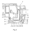
- FIG. 2 differs from the embodiment of FIG. 1 by the use of non-congruent profiles in the strips, which are therefore designated in FIG. 2 by (32, 33).
- the profile assigned to the outer edge (19) corresponds to the profiles of the strips (18 ', 18) which are described in connection with FIG. 1. Accordingly, it is the T-shape explained in more detail there with a web (21) and a flange (22).
- the profile of the profile (33) assigned to the inner edge (20) is different.
- This profile is designed as a glazing bead, i.e. it is a hollow chamber profile with a groove (34) which receives an elastic seal which seals on the double glazing (4). Chambers (35 and 36) are formed in the bar (33), which has a latching connection (37) with the inside of the frame of the casement profile (2).
- a bead (38) cooperates with a free leg of the latching connection, whereby the profile flange (39), which forms the inner section of the groove base, is elastically pressed onto the visible surface (15) with an inner projection (40).
- An angle leg (41) forms the inner wall of the groove (16) in which the decorative strip (17) is held.
- the profile strip (33) therefore simultaneously forms a glass strip, the geometry described is selected so that it forms the counter-locking after the glazing (4).
Landscapes
- Engineering & Computer Science (AREA)
- Civil Engineering (AREA)
- Structural Engineering (AREA)
- Securing Of Glass Panes Or The Like (AREA)
- Wing Frames And Configurations (AREA)
Applications Claiming Priority (2)
| Application Number | Priority Date | Filing Date | Title |
|---|---|---|---|
| DE4022006 | 1990-07-11 | ||
| DE19904022006 DE4022006A1 (de) | 1990-07-11 | 1990-07-11 | Fluegelrahmen aus profilierten rahmengliedern fuer fenster und tueren |
Publications (1)
| Publication Number | Publication Date |
|---|---|
| EP0465788A1 true EP0465788A1 (fr) | 1992-01-15 |
Family
ID=6410043
Family Applications (1)
| Application Number | Title | Priority Date | Filing Date |
|---|---|---|---|
| EP91107251A Withdrawn EP0465788A1 (fr) | 1990-07-11 | 1991-05-04 | Cadre pour portes et fenêtres comprenant des membres profilés |
Country Status (2)
| Country | Link |
|---|---|
| EP (1) | EP0465788A1 (fr) |
| DE (1) | DE4022006A1 (fr) |
Families Citing this family (1)
| Publication number | Priority date | Publication date | Assignee | Title |
|---|---|---|---|---|
| DE202019107047U1 (de) * | 2019-12-17 | 2021-03-18 | Rehau Ag + Co | Fenster- oder Türflügel sowie diesen umfassendes Fenster oder diesen umfassende Tür |
Citations (4)
| Publication number | Priority date | Publication date | Assignee | Title |
|---|---|---|---|---|
| DE1509727A1 (de) * | 1962-06-23 | 1969-05-22 | Giovanni Ongaro | Metallprofil zur Verwendung beim Bau von Tuer- und Fenstereinfassungen od.dgl. |
| EP0149991A1 (fr) * | 1983-11-16 | 1985-07-31 | Franz Silber | Fenêtre en bois pourvue d'un revêtement extérieur en métal léger |
| DE8717454U1 (de) * | 1987-07-20 | 1988-11-24 | Zapp, Wolfgang D., Creutzwald | Rahmen aus Strangprofilen |
| DE8901130U1 (de) * | 1989-02-02 | 1989-08-24 | Di Pietro, Giovanni, 6780 Pirmasens | Fenster oder Tür |
Family Cites Families (1)
| Publication number | Priority date | Publication date | Assignee | Title |
|---|---|---|---|---|
| DE3828009A1 (de) * | 1988-08-18 | 1990-02-22 | Wolfgang D Zapp | Rahmen aus strangprofilen |
-
1990
- 1990-07-11 DE DE19904022006 patent/DE4022006A1/de not_active Ceased
-
1991
- 1991-05-04 EP EP91107251A patent/EP0465788A1/fr not_active Withdrawn
Patent Citations (4)
| Publication number | Priority date | Publication date | Assignee | Title |
|---|---|---|---|---|
| DE1509727A1 (de) * | 1962-06-23 | 1969-05-22 | Giovanni Ongaro | Metallprofil zur Verwendung beim Bau von Tuer- und Fenstereinfassungen od.dgl. |
| EP0149991A1 (fr) * | 1983-11-16 | 1985-07-31 | Franz Silber | Fenêtre en bois pourvue d'un revêtement extérieur en métal léger |
| DE8717454U1 (de) * | 1987-07-20 | 1988-11-24 | Zapp, Wolfgang D., Creutzwald | Rahmen aus Strangprofilen |
| DE8901130U1 (de) * | 1989-02-02 | 1989-08-24 | Di Pietro, Giovanni, 6780 Pirmasens | Fenster oder Tür |
Also Published As
| Publication number | Publication date |
|---|---|
| DE4022006A1 (de) | 1992-01-23 |
Similar Documents
| Publication | Publication Date | Title |
|---|---|---|
| DE4142151A1 (de) | Fenster fuer ein fensterband | |
| EP0648310B1 (fr) | Profile composite | |
| EP0225473B1 (fr) | Battant de porte ou fenêtre | |
| DE3210253A1 (de) | Fensterkonstruktion | |
| EP1091081B1 (fr) | Dispositif de guidage pour un volet roulant, un store enroulable ou similaire | |
| DE3817775C2 (fr) | ||
| WO1991006738A1 (fr) | Ornement pour chassis de battants | |
| EP1608837A1 (fr) | Profile de chassis de battant et fenetre en plastique a vitrage colle | |
| EP0063623A1 (fr) | Ensemble constructif de plusieurs profilés assortis, extrudés en matière plastique, pour la fabrication de fenêtres, portes et analogues | |
| CH701104B1 (de) | Fenster oder Tür mit Abdeckblende, Verwendung einer Abdeckblende und System zur Bildung von Fenstern oder Türen. | |
| EP0010180B1 (fr) | Petits-bois d'une fenêtre à petits-bois | |
| DE29521122U1 (de) | Holz-Alu-Fenster | |
| EP0465788A1 (fr) | Cadre pour portes et fenêtres comprenant des membres profilés | |
| EP0750089A1 (fr) | Cadre de recouvrement pour fenêtre | |
| EP0084619A1 (fr) | Vitrage additionnel pour fenêtres | |
| DE29607602U1 (de) | Abdichtleiste zur Abdichtung und Abdeckung von äußeren und inneren Fugen an Bauwerken | |
| EP1524378B1 (fr) | Façade de montants et de traverses avec fenêtres | |
| DE20117000U1 (de) | Fenster- oder Türrahmen und daraus gebildete Fassade | |
| AT396385B (de) | Stockrahmenprofil | |
| DE2621489A1 (de) | Fenster oder tuere mit einer scheibe, insbesondere einer isolierglasdoppelscheibe und/oder einer fuellung | |
| DE19612491C2 (de) | Glasdichtungsleiste für Rahmen von Fenstern oder Türen mit eingesetzter Verglasung | |
| EP3832065B1 (fr) | Profilé de guidage pour une fenêtre ou une porte avec un caisson pour un volet roulant | |
| DE3801172C2 (de) | Fenster | |
| EP0482278A1 (fr) | Décoration pour cadre de battant | |
| DE8714642U1 (de) | Fenster mit einem Fensterrahmen |
Legal Events
| Date | Code | Title | Description |
|---|---|---|---|
| PUAI | Public reference made under article 153(3) epc to a published international application that has entered the european phase |
Free format text: ORIGINAL CODE: 0009012 |
|
| AK | Designated contracting states |
Kind code of ref document: A1 Designated state(s): AT BE CH DE DK ES FR GB GR IT LI LU NL SE |
|
| STAA | Information on the status of an ep patent application or granted ep patent |
Free format text: STATUS: THE APPLICATION IS DEEMED TO BE WITHDRAWN |
|
| 18D | Application deemed to be withdrawn |
Effective date: 19920716 |