EP0465876A2 - Charrue, notamment charrue double tour telle que charrue réversible à disques et similaire - Google Patents
Charrue, notamment charrue double tour telle que charrue réversible à disques et similaire Download PDFInfo
- Publication number
- EP0465876A2 EP0465876A2 EP91109950A EP91109950A EP0465876A2 EP 0465876 A2 EP0465876 A2 EP 0465876A2 EP 91109950 A EP91109950 A EP 91109950A EP 91109950 A EP91109950 A EP 91109950A EP 0465876 A2 EP0465876 A2 EP 0465876A2
- Authority
- EP
- European Patent Office
- Prior art keywords
- plow
- frame
- frame unit
- rotor
- shaft
- Prior art date
- Legal status (The legal status is an assumption and is not a legal conclusion. Google has not performed a legal analysis and makes no representation as to the accuracy of the status listed.)
- Withdrawn
Links
Images


Classifications
-
- A—HUMAN NECESSITIES
- A01—AGRICULTURE; FORESTRY; ANIMAL HUSBANDRY; HUNTING; TRAPPING; FISHING
- A01B—SOIL WORKING IN AGRICULTURE OR FORESTRY; PARTS, DETAILS, OR ACCESSORIES OF AGRICULTURAL MACHINES OR IMPLEMENTS, IN GENERAL
- A01B5/00—Ploughs with rolling non-driven tools, e.g. discs
- A01B5/10—Ploughs with rolling non-driven tools, e.g. discs mounted or partly-mounted on tractors
- A01B5/14—Alternating ploughs
Definitions
- the invention relates to a plow, in particular rotor plow such as disc plow, e.g. with reversibility by swiveling the plow tools and the like machine.
- the support in particular with reversible rotor plows such as disc sweeping plows, is insufficient because e.g. the device for a changing use of the land support wheels required on both sides and the adjustment device for the swivel frame and the furrow wheel are difficult to reconcile with one another in terms of space and drive and are disproportionately expensive, so that these problems have not been able to be solved so far and the number of discs and thus the working width is limited .
- a bed plow which has a plow front frame designed as a coupling of a three-point linkage, in which, as is usually the case with bed plows, the land-side connecting pin to the lower links of the tractor is arranged higher than the furrow-side on the shaft opposite.
- the plow is therefore always inclined towards the land side to compensate for the inclination of the tractor working in the furrow.
- the shaft is fixed on an adjusting block and only rotated up to 60 ° to one side to adjust the working width.
- a pin holder with pins of different diameters offset with respect to the shaft axis must be used on each end of the shaft.
- the shaft is released from the jack and rotated by 180 ° by hand and then reconnected to the jack; or it is releasably attached to the shaft pivoted pin holder on the shaft connected to the adjusting bracket accordingly.
- the framework-like frame consists of three longitudinal and transverse bars, which are reinforced by diagonal struts.
- a pivot bearing is arranged in the middle by means of support plates, on which a pivot frame with the disks arranged on a central rotatable shaft can be pivoted in both reversed positions by a differential cylinder.
- the swivel frame is further supported with rollers on a supporting ring which is fastened to the plow frame and takes up the width thereof.
- the plow is carried by two medium hydraulic transport wheels during transport.
- Additional hydraulically swiveling pairs of wheels at the front and rear of the plow frame serve as support during plowing, one of which runs alternately in the old and one in the rear alternately in the new furrow and one free third on the land side.
- a drive of the disks is not provided here.
- a disc plow with driven discs is known from EP-A 0 149 488, in which an angular gear arranged on the central shaft can be connected to the tractor PTO.
- a reversal of the working direction is not possible with such a plow construction, because at the same time the direction of rotation is reversed and there is an indispensable support on each side and the furrow wheel would have to be adjustable.
- the Number of disks is severely limited due to the permissible transport width.
- the object of the invention is generally to provide a structurally simple plow, in particular driven reversible rotor plow, according to the preamble features of claims 1-5 and 21, the inclination of which, when working on slopes, on bumps and the like, in particular when reversing rotor plows, if necessary is adjustable on both sides by 180 °, which can be alternately supported on the respective land side against drift and possibly for depth adjustment, in which the pivot bearing of the swivel frame on the plow frame is more compact and less tipping and less wear-resistant and which, despite greater torsional stiffness, is lighter and therefore more maneuverable and easy to design for a larger number of plowing tools while observing the permissible transport width and can be attached, attached or saddled to the tractor and, if necessary, driven by it in both directions of rotation and in which, if applicable, all adjusting devices, e.g. in the case of a reversible rotor plow, are connected to one another in terms of drive
- the object of the invention is achieved as required by a solution complex of the characterizing features of claims 1 to 5 or a combination of individual ones thereof, and in a particularly simplified embodiment of a driven reversible rotor plow according to the characterizing features of claim 21.
- Another advantage is that the plow can be easily transported without further measures and without obstruction when the swivel frame is swung in under the plow frame, and a transport wheel that can be swung out, for example, about a horizontal axis can also be used.
- 3 is a plow frame of a reversible rotor plow consisting of longitudinal bars 3a, 3a 'and transverse bars 3b, 3b', 3b '', 3b '', with 1 a mounting triangle provided at the front for mounting the same on one by its lower links 2 indicated tractor and with 5 a swiveling frame consisting of longitudinal spars 5a, 5a 'and transverse spars 5b, 5b', 5b '' on a turntable 4 in reversing positions with existing plows 7 on a shaft 6.
- the plow frame 3 and the mounting triangle 1 form a first frame unit , by means of which the reversible rotor plow can be coupled to the tractor indicated by its lower links 2, while the swivel frame 5 forms a second frame unit, which with the first frame unit 1-3 by means of the turntable 4 provided between the first and the second frame unit with at least approximately perpendicular Axis is rotatably connected.
- the slewing ring 4 is fastened both to the two longitudinal bars 3a, 3a 'of the plow frame 3 and to the two longitudinal bars 5a, 5a' of the swivel frame 5.
- Land support wheels are designated with 19a, 19b and furrow wheels with 13a, 13b.
- 1c is the upper link traverse about which the plow, raised for transport by the lower links 2 and lowered for work, pivots.
- the mounting rail 1a designed as a shaft is about an axis running at least approximately horizontally and at least approximately at right angles to the direction of travel on an offset 3c of the longitudinal bars 3a, 3a 'of the plow frame that extends towards the floor A.
- 3 or extension of the triangle 1 mounted and provided at their ends with opposite, in one plane extending front cranks 15a, 15b, on whose length-adjustable arms 16a, 16b are arranged their connecting pins 1b connected to the lower links 2.
- chains 12a and 12b are provided for actuating the device for lateral adjustment, which chains on the one hand on load arms 21a and 21b and one on the bottom of one on the cross bar 3b '''of the plow frame 3, with the geometric axis of the slewing ring 4 centered axis 11 mounted double rocker arm 21 and on the other hand on the mounting rail 1 a, this in the sense of a double pull on the one hand from above and the other from below to their circumference, attached.
- the power arm 22a which is articulated at its end to a piston rod 29 of a linear motor 28 (for example a working cylinder) of an angle lever 22, which is also mounted on an upper step seat of the axis 11, is connected to the load arm 21a by a pin 10 or driver.
- a linear motor 28 for example a working cylinder
- a shaft 17 is rotatably mounted approximately in the middle between the mounting rail 1a and the double rocker arm 21 on the longitudinal spars 3a, 3a 'of the plow frame 3, at the two ends of which oppose each other in one plane extending end crank arms 18 are attached which, like the end cranks 15a, 15b, lie horizontally in the transport position of the plow.
- chains 24a, 24b are articulated on the load arms 21a, 21b of the double rocker arm 21, which encompass the shaft 17, one on the outside (24a) from above and the other (24b) from below in the sense of the described double pull on the outer circumference are attached.
- chains 27a and 27b are also attached, which are suspended on the mounting rail 1a in the sense of the double pull described above.
- the land support wheel 19a is additionally brought into the support position on the land side.
- the land support wheels 19a, 19b for absorbing the strong lateral forces consist of guide disks 19c and support tires 19d.
- Tension locks 31 serve to tension the chains 12a, 12b, 24a, 24b, 27a, 27b.
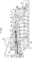
- the plow tools 7 which are arranged on the shaft 6 and are designed here as disks are driven.
- the cross bar 3b ' i.e. in the area of the front of the plow frame 3, where the triangle 1 extends
- a reversing gear 30 is arranged, the position of which relative to the plow frame 3 and the triangle 1, during the pivoting of the pivot frame 5 and the rotor 6-7, therefore remains constant, and which also serves as temporary storage.
- the reversing gear 30 has a connection piece 30a for connection to the tractor PTO shaft serving as the drive source, while on the connection piece 30b - as illustrated in FIGS.
- connection piece 8a of a transmission 8 arranged at the rear on the swivel frame 5 connecting drive shaft 8b is connected.
- the cardan shaft 8b forming a shaft train runs higher than and above the swivel frame 5.
- a drive spur gear 8c of the transmission 8 forms a chain hoist 6b with a drive spur gear 6a coupled to the rear end of the shaft 6.
- the reversing gear 30 is reversed when the plow is reversed by a shift linkage 9 which is connected to the chain 27a by a driver 42, the direction of rotation of the rotor corresponding to the working position of the swivel frame 5 and the rotor 6-7 carried by this being set.
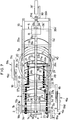
- FIGS. 5 and 6 show another embodiment of a furrow wheel 39 which is set automatically when the swivel frame 5 is pivoted.
- This is mounted with its support arm 38 on a joint 36 (with at least approximately a vertical axis) of the swivel frame 5. Holes 37a serve to adjust the depth thereof.
- the support arm 38 is, as can be seen with a shaft 35d Parallel rocker 35 connected, the rods 35a, 35a 'articulated parallel to the longitudinal bars 3a, 3a' of the plug frame 3 at pivot joints 35c, on the other hand articulatedly connected to a crossbar 35b actuating the shaft 35d.
- both the geometric axis of the joint 36 and the axis of symmetry of the furrow wheel 39 are contained in the vertical plane which contains the longitudinal axis of the shaft 6.
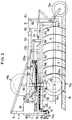
- FIGS. 7 and 8 show a further embodiment of a plow according to the invention, which is approximately similar to the plow according to FIGS. 5 and 6, but whose rotor 6-7 is driven as in the exemplary embodiment according to FIGS. 1-4.
- the furrow wheel 39 ' the position of which is similar to the position of the furrow wheel 39, during transport as a transport wheel on which the plow can be supported. For this, e.g. the top link of the tractor can be removed.
- the reversible rotor plow works as follows: In the plow in FIG. 4, the swivel frame 5 is indicated with solid lines in a working position and previously indicated by dashed lines in the working position. In the change position, the plow was lifted by the lower links 2, pivoting about the upper link 1c.
- the linear motor 28 is actuated almost simultaneously, which pivots the swivel frame 5 by 90 ° from the dashed position to the other side via the load arm 22b of the angle lever 22, the double rocker 21 connected thereto simultaneously via the chains 24b and 27b the land support wheels 19a, 19b and the front cranks 15a, 15b also spend in the reverse position, whereby the plow turns by turning the plug pins 1b in the direction indicated by arrow b against the inclination of the tractor with a rear wheel in the furrow about the x-axis Plow tools tilts parallel to the ground A and the land support wheel 19a on the land side is used and the furrow wheel 13b rolls in the furrow drawn by the last plow tool 7.
- the length of the force and load arms of the angle lever 22, the double rocker arm 21 and the rods 35a, 35a 'and the diameter of the shafts 1a and 17 can be coordinated in a simple manner so that the moving plow parts do not hinder their movement and are ready for use at the same time. This advantageously enables a short overall length even of plows having a large number of plowing tools.
- the screwing of the turntable 4, indicated by holes 40, is used to move the swivel frame 5 on the longitudinal spars 3a, 3a 'of the plow frame 3, so that adaptation to differently wide tractors is possible in a particularly simple manner.
- the plow with ground drive of the plow tools 7 can be used.
- An analogous embodiment of the invention is of course also possible with disc seed plows and similarly operated other machines.
- the chains 24a, 24b, 27a, 27b are of course also by equivalent transmission links such as replaceable with linkage.
- the shaft train which transmits the driving force from the reversing gear 30 to the gear 8 is formed by a single cardan shaft 8b.
- multiple shafts can be used in other embodiments.
- the invention can also be used in semi-mounted plows or drawn plows.
Landscapes
- Life Sciences & Earth Sciences (AREA)
- Engineering & Computer Science (AREA)
- Mechanical Engineering (AREA)
- Soil Sciences (AREA)
- Environmental Sciences (AREA)
- Soil Working Implements (AREA)
Priority Applications (1)
| Application Number | Priority Date | Filing Date | Title |
|---|---|---|---|
| EP93110913A EP0592773B1 (fr) | 1990-06-20 | 1991-06-18 | Charrue double-tour telle que charrue réversible à disques et similaire |
Applications Claiming Priority (2)
| Application Number | Priority Date | Filing Date | Title |
|---|---|---|---|
| DE4019612 | 1990-06-20 | ||
| DE4019612A DE4019612C2 (de) | 1990-06-20 | 1990-06-20 | Pflug, insbesondere Scheibenkehrpflug |
Related Child Applications (1)
| Application Number | Title | Priority Date | Filing Date |
|---|---|---|---|
| EP93110913.6 Division-Into | 1991-06-18 |
Publications (2)
| Publication Number | Publication Date |
|---|---|
| EP0465876A2 true EP0465876A2 (fr) | 1992-01-15 |
| EP0465876A3 EP0465876A3 (en) | 1992-04-22 |
Family
ID=6408711
Family Applications (2)
| Application Number | Title | Priority Date | Filing Date |
|---|---|---|---|
| EP93110913A Expired - Lifetime EP0592773B1 (fr) | 1990-06-20 | 1991-06-18 | Charrue double-tour telle que charrue réversible à disques et similaire |
| EP19910109950 Withdrawn EP0465876A3 (en) | 1990-06-20 | 1991-06-18 | Plough, particularly double-turn plough like reversible disk plough and the like |
Family Applications Before (1)
| Application Number | Title | Priority Date | Filing Date |
|---|---|---|---|
| EP93110913A Expired - Lifetime EP0592773B1 (fr) | 1990-06-20 | 1991-06-18 | Charrue double-tour telle que charrue réversible à disques et similaire |
Country Status (3)
| Country | Link |
|---|---|
| EP (2) | EP0592773B1 (fr) |
| JP (1) | JPH04229101A (fr) |
| DE (2) | DE4019612C2 (fr) |
Family Cites Families (10)
| Publication number | Priority date | Publication date | Assignee | Title |
|---|---|---|---|---|
| DE1156264B (de) * | 1962-05-17 | 1963-10-24 | Rabewerk Clausing Heinrich | Als Koppel eines Dreipunktgestaenges ausgebildetes Pflugvordergestell eines Beetpfluges |
| CH433843A (de) * | 1964-11-17 | 1967-04-15 | Lely Nv C Van Der | Scheibenpflug |
| GB1497259A (en) * | 1975-06-19 | 1978-01-05 | Pettit Ltd F | Reversible ground-working implement |
| ES446753A2 (es) * | 1976-04-07 | 1978-01-16 | Hijos De Jose Tubert S L | Perfeccionamientos en mecanismos inversores automaticos paraarados de discos. |
| GB2002211B (en) * | 1977-08-11 | 1982-02-10 | Allen W | Reversible disc plough |
| JPS60116802U (ja) * | 1984-01-17 | 1985-08-07 | スタ−農機株式会社 | 耕耘砕土機 |
| DE3778704D1 (de) * | 1986-08-12 | 1992-06-04 | Denis Coste | Pflug mit symmetrischen koerpern. |
| WO1989006897A1 (fr) * | 1988-01-28 | 1989-08-10 | Giuseppe Mario Sartor | Charrue |
| US4869327A (en) * | 1988-07-07 | 1989-09-26 | Korf Alfred W | Reversible one-way disk plow |
| DE3838483A1 (de) * | 1988-11-12 | 1990-05-17 | Hermann Buettner | Wendepflug |
-
1990
- 1990-06-20 DE DE4019612A patent/DE4019612C2/de not_active Expired - Fee Related
-
1991
- 1991-06-18 EP EP93110913A patent/EP0592773B1/fr not_active Expired - Lifetime
- 1991-06-18 EP EP19910109950 patent/EP0465876A3/de not_active Withdrawn
- 1991-06-18 DE DE59108913T patent/DE59108913D1/de not_active Expired - Fee Related
- 1991-06-20 JP JP3175943A patent/JPH04229101A/ja active Pending
Also Published As
| Publication number | Publication date |
|---|---|
| DE4019612A1 (de) | 1992-01-09 |
| EP0592773A3 (en) | 1994-06-01 |
| DE59108913D1 (de) | 1998-02-05 |
| EP0592773A2 (fr) | 1994-04-20 |
| DE4019612C2 (de) | 1993-11-25 |
| JPH04229101A (ja) | 1992-08-18 |
| EP0592773B1 (fr) | 1997-12-29 |
| EP0465876A3 (en) | 1992-04-22 |
Similar Documents
| Publication | Publication Date | Title |
|---|---|---|
| EP0089053B1 (fr) | Machine pour le travail du sol | |
| EP2605632B1 (fr) | Machine agricole tractée dotée d'un rouleau | |
| DE3343847C2 (fr) | ||
| DE69117842T2 (de) | Bodenbearbeitungsmaschine | |
| DE3105639A1 (de) | "geraetekombination fuer die landwirtschaft" | |
| DE3218385C2 (fr) | ||
| DE2622649C2 (de) | Schlepperbetriebene Bodenbearbeitungsmaschine | |
| DE69504081T2 (de) | Schlepper-aufgehangene mähmaschine | |
| EP0350513B1 (fr) | Appareil pour travailler le sol | |
| DE3028094C3 (de) | Anbaudrehpflug | |
| EP2710869A1 (fr) | Dispositif porte-outils frontal d'un véhicule de travail | |
| EP0211967A1 (fr) | Combinaison d'outils de travail de la terre utilisée en agriculture | |
| DE3419946A1 (de) | Bodenbearbeitungsgeraet | |
| DE19954423A1 (de) | Landwirtschaftliche Bestellkombination mit günstiger Schwerpunktsverlagerung | |
| EP0359896B1 (fr) | Machine combinée | |
| DE4128501A1 (de) | Heuwerbungsmaschine | |
| DE69912671T2 (de) | Geräteunterstützungsvorrichtung insbesondere für Landwirtschaft, Weinbau und Baumgärtnerei | |
| EP0340539B1 (fr) | Machine combinée pour le travail agricole et procédé pour son relevage | |
| DE2924732C2 (de) | Bodenbearbeitungsmaschine | |
| DE29714523U1 (de) | Gezogene Mähmaschine mit einer seitlich angehängten Zugstange | |
| DE823816C (de) | Ein- oder mehrschariger Beetpflug zum Anbauen an eine Zugmaschine | |
| DE2521023A1 (de) | Vielschariger aufsattelpflug | |
| EP0465876A2 (fr) | Charrue, notamment charrue double tour telle que charrue réversible à disques et similaire | |
| DE3337193C2 (fr) | ||
| DE3431796A1 (de) | Bodenbearbeitungsmaschine |
Legal Events
| Date | Code | Title | Description |
|---|---|---|---|
| PUAI | Public reference made under article 153(3) epc to a published international application that has entered the european phase |
Free format text: ORIGINAL CODE: 0009012 |
|
| AK | Designated contracting states |
Kind code of ref document: A2 Designated state(s): BE DE DK ES FR GB IT NL SE |
|
| PUAL | Search report despatched |
Free format text: ORIGINAL CODE: 0009013 |
|
| AK | Designated contracting states |
Kind code of ref document: A3 Designated state(s): BE DE DK ES FR GB IT NL SE |
|
| 17P | Request for examination filed |
Effective date: 19920603 |
|
| 17Q | First examination report despatched |
Effective date: 19920807 |
|
| GRAH | Despatch of communication of intention to grant a patent |
Free format text: ORIGINAL CODE: EPIDOS IGRA |
|
| STAA | Information on the status of an ep patent application or granted ep patent |
Free format text: STATUS: THE APPLICATION IS DEEMED TO BE WITHDRAWN |
|
| 18D | Application deemed to be withdrawn |
Effective date: 19960326 |