EP0465985A1 - Cage de sauvetage, en particulier pour pompe à incendie - Google Patents
Cage de sauvetage, en particulier pour pompe à incendie Download PDFInfo
- Publication number
- EP0465985A1 EP0465985A1 EP91110906A EP91110906A EP0465985A1 EP 0465985 A1 EP0465985 A1 EP 0465985A1 EP 91110906 A EP91110906 A EP 91110906A EP 91110906 A EP91110906 A EP 91110906A EP 0465985 A1 EP0465985 A1 EP 0465985A1
- Authority
- EP
- European Patent Office
- Prior art keywords
- ladder
- rescue cage
- rescue
- cage according
- cage
- Prior art date
- Legal status (The legal status is an assumption and is not a legal conclusion. Google has not performed a legal analysis and makes no representation as to the accuracy of the status listed.)
- Granted
Links
- 238000010586 diagram Methods 0.000 description 3
- 230000005484 gravity Effects 0.000 description 2
- 238000000034 method Methods 0.000 description 2
- 230000000903 blocking effect Effects 0.000 description 1
- 238000010276 construction Methods 0.000 description 1
- 230000010354 integration Effects 0.000 description 1
- 238000011144 upstream manufacturing Methods 0.000 description 1
Images



Classifications
-
- A—HUMAN NECESSITIES
- A62—LIFE-SAVING; FIRE-FIGHTING
- A62C—FIRE-FIGHTING
- A62C27/00—Fire-fighting land vehicles
-
- A—HUMAN NECESSITIES
- A62—LIFE-SAVING; FIRE-FIGHTING
- A62B—DEVICES, APPARATUS OR METHODS FOR LIFE-SAVING
- A62B5/00—Other devices for rescuing from fire
-
- E—FIXED CONSTRUCTIONS
- E06—DOORS, WINDOWS, SHUTTERS, OR ROLLER BLINDS IN GENERAL; LADDERS
- E06C—LADDERS
- E06C5/00—Ladders characterised by being mounted on undercarriages or vehicles Securing ladders on vehicles
- E06C5/02—Ladders characterised by being mounted on undercarriages or vehicles Securing ladders on vehicles with rigid longitudinal members
- E06C5/04—Ladders characterised by being mounted on undercarriages or vehicles Securing ladders on vehicles with rigid longitudinal members capable of being elevated or extended ; Fastening means during transport, e.g. mechanical, hydraulic
Definitions
- the invention relates to a rescue cage which is articulated in a standing or semi-vertical manner at the upper end of a turntable ladder or the like.
- a rescue cage of the above type is known, which is articulated in a standing or semi-vertical manner on the rescue ladder of a fire protection vehicle, i.e. has a pivot axis which is located below the center of gravity of the basket.
- the rescue cage has a folding ladder on the front of the basket, approximately halfway up, which can be stored in a window opening of a house in the event of a rescue with the aerial ladder erected, in order to rescue people in the house.
- the rescue cage also has another folding ladder on the opposite side of the cage. The latter folding ladder is used to climb the rescue cage from the ground.
- the turntable ladder is in its upright rescue position, the rescue cage itself being moved to the lowest position on the turntable ladder.
- the turntable ladder In the case of the known fire protection vehicle, the turntable ladder must be swung up from the horizontal driving position into the upright rescue position before the rescue and the rescue cage must be moved to the lowest position on the ladder before the folding ladder located on the rear of the rescue cage can be swung to the ground and then People can climb into the basket. This is comparatively cumbersome and time consuming. Particularly with fire protection vehicles or the like, very fast deployment is important.
- the object of the invention is the further development of the aforementioned prior art by creating a standing or semi-standing rescue cage of the type mentioned, which is very simple in construction and can nevertheless be handled quickly and safely.
- the essence of the invention is that a single ladder is hinged to the front of the rescue cage in the area of the basket bottom and is provided with at least one extendable ladder part.
- the vertical rescue cage can already be in the horizontal driving position of the aerial ladder, i.e. with the ladder parked above the cab of the fire protection vehicle, you can climb directly from the ground via the swung-down and extended ladder.
- the turntable ladder does not have to be moved into its upright rescue position first.
- the rescue cage is already at the front end of the ladder.
- the rescue cage including the accompanying person in the basket can be quickly moved to a place of use, window ledge of a house or the like.
- the rescued can be rescued quickly and safely just as quickly.
- the rescue cage is therefore tactically faster than known cage arrangements.
- a greater depth can also be achieved via the rescue cage when the turntable ladder is upright and the ascent ladder swung down and extended when descending into balconies, pits or the like.
- the known ladder on the front of the basket according to DE-PS 23 28 990 can only be used when the basket is approaching the window ledge or the like.
- An ascent ladder can also be saved by the invention compared to the known rescue cage mentioned at the beginning.
- the ladders according to DE-OS 34 17 714 which are also known on the front of the basket, are not suitable, particularly because of their one-piece design, to climb the rescue cage directly from the ground when the turntable ladder is in a horizontal position, in particular not when a (generic) rescue cage is arranged standing or standing on the ladder .
- the front ladder corresponds to the known folding ladder according to DE-PS 23 28 990, which is only used when the aerial ladder is erected.
- a further development of the invention provides that the ladder in its swung-up retracted position at least partially covers the access opening to the rescue cage and can be locked by a locking lock, which in particular a spring-loaded Ver locking bolt.
- the ladder also preferably has an electric or hydraulic drive which enables the ladder to be pivoted.
- the electric or hydraulic drive can also unlock the aforementioned locking lock. It is preferably compactly integrated in the rescue cage floor and can be operated by small and tall operators using several pressure switches in the rescue cage, on the underside of the basket floor and on the outside of the vehicle from the rescue cage or from the ground. At the same time, the entire swivel range of the boarding ladder can be visually viewed during an actuation process.
- the extendable ladder part of the ladder is usually manually telescopic and guided in the spar of the articulated ladder part.
- the telescopic process can also be carried out electrically or hydraulically by external energy.
- the hinged ladder part and the extendable ladder part are the same rung or the same rung spacing and can therefore be climbed safely in both positions.
- a fire protection vehicle (3) comprises an upper aerial ladder (2), the ladder of which is stored horizontally in the driving position above the driver's cab.
- a rescue cage (1) which is known per se, is articulated semi-vertically at the upper or front end of the turntable ladder or the top turntable ladder part, the rescue cage being illustrated in its vertical position of use.
- the articulation axis of the rescue cage is located in the horizontal transverse direction slightly below the center of gravity of the cage.
- the rescue cage is designed as a so-called slip-on basket and can be "slipped" over the ladder set in its horizontal driving position, which significantly shortens the overall length of the vehicle.
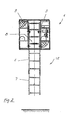
- a ladder (20) is articulated about a horizontal transverse axis in the cage floor (5), which according to the embodiment of the drawing consists of two ladder parts (6, 7): one articulated on the cage floor (5) Ladder part (6) and an extendable ladder part (7).
- Each individual ladder part (6, 7) has approximately the height of the rescue cage (1).
- Both ladder parts (6, 7) completely cover the front access opening (8) of the rescue cage (1) in the retracted, swiveled-in state. In the position blocking the access opening (8), the ladder (20) is locked by side locking locks (9).
- Each locking lock has a spring-loaded locking bolt which is slidably mounted in the front basket wall.
- the arrangement is such that when the ascent ladder (20) is swiveled up, both side locking bolts snap into the lateral recesses of the ascent ladder (20) by spring force and lock the ladder securely.
- the side locking locks (9) are unlocked by a hydraulic drive (10) for pivoting the ladder (20), which simultaneously performs the pivoting movement of the ladder (20).
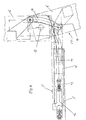
- the hydraulic drive (10) is integrated in the basket base (5) and is shown in greater detail in FIGS. 4 and 5.
- the hydraulic drive (10) has a hydraulic cylinder (12), the piston rod (13) of which is articulated on one end of a toggle lever (14), the articulation point being guided in the basket base (5).
- the other end of the toggle lever (14) is articulated on the articulated ladder part (6) of the ascent ladder (20) eccentrically to the horizontal ladder pivot axis (19). If hydraulic pressure is applied to the hydraulic cylinder (12), the piston rod (13) moves to the right as shown in FIG. 4, so that the toggle lever (14) according to the dash-dotted line the ascent ladder (20) from its 15 ° ascent position to its vertical , pivots the entry opening (8) of the rescue cage (1) in the closed position, that is to say the toggle lever (14) assumes the position shown in solid lines according to FIG. 4.
- the hydraulic cylinder (12) as can be seen in particular from the circuit diagram in FIG. 5, can be acted upon hydraulically from both sides, so that the ascent ladder (20) pivots in the other direction when the other side of the piston is acted upon can be.
- the locking locks are unlocked by hydraulically actuated unlocking cylinders (17) which are assigned to each locking lock (9).
- the unlocking cylinders move the spring-biased assigned locking bolts against the force of the spring into the unlocking position, whereupon the pivoting movement of the ladder (20) can be carried out by the same hydraulic drive (10).
- the circuit diagram of the hydraulic circuit illustrated in more detail in FIG. 5 comprises a hydraulic pressure source (16), an electromagnetically operable 3/4 way valve, which are arranged upstream of the aforementioned cylinders (hydraulic cylinder 12 and unlocking cylinder 17).
- the 3/4 way valve is shown in its locked position.
- the valve (15) according to FIG. 5 is set to the left so that the connections (P) and (A) as well as (B) and (T) are connected to one another.
- the valve (15) is placed electromagnetically in its other position, so that the connections (A) and (T) and the connections (P) and (B) are connected to one another.
- the hydraulic drive (10) is actuated by pressure switches (11) which are arranged in the rescue cage (1) and on the underside of the rescue cage as well as on the outside of the cab, as can be seen in particular in FIG. 1.
- the pressure switches (11) are arranged so that the pivoting movement of the basket can be seen by an operator in every position of use.
- the same rungs when the ladder (20) is retracted or the rungs spacing when the ladder is pulled out is achieved in particular by an inner stop (18) which is welded to at least one side rail (21) of the extendable ladder part (7) according to FIG.
- the stop (18) is located in the area of the uppermost end of the extendable ladder part (7) as shown in FIG. 1 and is movable back and forth between two associated counter-stops of the articulated ladder part (6), which are in the area of the uppermost and lowermost ends of the articulated ladder part (6) are located and thus define both end positions of the pull-out ladder (20).
- the telescopic ladder can also be used when the turntable ladder (2) is upright, in order to be able to enter greater depths when descending into balconies or the like.
- the swivel drive is accommodated in a space-saving manner due to the integration into the basket floor, the swivel kinematics illustrated in FIG. 4 also being able to be replaced by a hydraulic swivel motor which carries out the swiveling mounted directly on the axis of rotation.
- a lever is attached to the door lock itself, which enables the entrance door of the rescue cage (1) to be opened if the electrical or hydraulic system fails.
- the invention is not only suitable for fire protection vehicles (3), but also for telescopic work platforms, articulated mast platforms, aerial work platforms or the like.
Landscapes
- Health & Medical Sciences (AREA)
- Business, Economics & Management (AREA)
- Emergency Management (AREA)
- Engineering & Computer Science (AREA)
- Mechanical Engineering (AREA)
- Public Health (AREA)
- General Health & Medical Sciences (AREA)
- Ladders (AREA)
Applications Claiming Priority (2)
| Application Number | Priority Date | Filing Date | Title |
|---|---|---|---|
| DE4021285 | 1990-07-04 | ||
| DE4021285A DE4021285A1 (de) | 1990-07-04 | 1990-07-04 | Rettungskorb insbesondere eines brandschutzfahrzeuges |
Publications (2)
| Publication Number | Publication Date |
|---|---|
| EP0465985A1 true EP0465985A1 (fr) | 1992-01-15 |
| EP0465985B1 EP0465985B1 (fr) | 1996-02-21 |
Family
ID=6409635
Family Applications (1)
| Application Number | Title | Priority Date | Filing Date |
|---|---|---|---|
| EP91110906A Expired - Lifetime EP0465985B1 (fr) | 1990-07-04 | 1991-07-02 | Cage de sauvetage, en particulier pour pompe à incendie |
Country Status (2)
| Country | Link |
|---|---|
| EP (1) | EP0465985B1 (fr) |
| DE (2) | DE4021285A1 (fr) |
Cited By (1)
| Publication number | Priority date | Publication date | Assignee | Title |
|---|---|---|---|---|
| CN101293126B (zh) * | 2008-06-26 | 2012-04-18 | 四川宁江精密工业有限责任公司 | 移动往复式救生装置 |
Citations (3)
| Publication number | Priority date | Publication date | Assignee | Title |
|---|---|---|---|---|
| GB173904A (en) * | 1920-10-18 | 1922-01-18 | Edwin Horice Haney | Fire rescue apparatus |
| DE2139798A1 (de) * | 1971-08-09 | 1973-02-22 | Metz Gmbh Carl | Vorrichtung zum ablegen eines an der spitze eines tragbalkens stehend angelenkten arbeits- und/oder rettungskorbes |
| GB2158414A (en) * | 1984-05-12 | 1985-11-13 | Iveco Magirus | A rescue or servicing cage |
-
1990
- 1990-07-04 DE DE4021285A patent/DE4021285A1/de not_active Withdrawn
-
1991
- 1991-07-02 EP EP91110906A patent/EP0465985B1/fr not_active Expired - Lifetime
- 1991-07-02 DE DE59107421T patent/DE59107421D1/de not_active Expired - Fee Related
Patent Citations (3)
| Publication number | Priority date | Publication date | Assignee | Title |
|---|---|---|---|---|
| GB173904A (en) * | 1920-10-18 | 1922-01-18 | Edwin Horice Haney | Fire rescue apparatus |
| DE2139798A1 (de) * | 1971-08-09 | 1973-02-22 | Metz Gmbh Carl | Vorrichtung zum ablegen eines an der spitze eines tragbalkens stehend angelenkten arbeits- und/oder rettungskorbes |
| GB2158414A (en) * | 1984-05-12 | 1985-11-13 | Iveco Magirus | A rescue or servicing cage |
Cited By (1)
| Publication number | Priority date | Publication date | Assignee | Title |
|---|---|---|---|---|
| CN101293126B (zh) * | 2008-06-26 | 2012-04-18 | 四川宁江精密工业有限责任公司 | 移动往复式救生装置 |
Also Published As
| Publication number | Publication date |
|---|---|
| DE59107421D1 (de) | 1996-03-28 |
| EP0465985B1 (fr) | 1996-02-21 |
| DE4021285A1 (de) | 1992-01-09 |
Similar Documents
| Publication | Publication Date | Title |
|---|---|---|
| EP2867066B1 (fr) | Véhicule avec une échelle d'accès télescopique | |
| DE2620683C3 (de) | Einstieganordnung für ein Nahverkehrsfahrzeug, insbesondere Schienenfahrzeug | |
| DE2535779A1 (de) | Rettungsgondel | |
| DE102015007562A1 (de) | Selbstfahrende Bodenfräsmaschine, insbesondere Straßenfräse, Recycler, Stabilisierer oder Surface-Miner, mit integrierter Wartungsplatte | |
| EP3341316B1 (fr) | Cabine d'ascenseur dotee d'une echelle amovible depuis l'interieur | |
| EP2030831A2 (fr) | Véhicule militaire destiné au transport de personnes | |
| EP2829663B1 (fr) | Tourelle pour un engin de chantier | |
| DE19525594A1 (de) | Motorisiertes Instandsetzungsgerät, insbesondere zur Instandsetzung eines Panzers | |
| EP2910511B1 (fr) | Cabine dotée d'un toit de protection réglable | |
| DE69305239T2 (de) | Feuerwehrfahrzeug mit dachseitigem Transportgestell für Leitern | |
| DE102014010488B4 (de) | Heckrotorfräse mit bewegbarem Aufstieg | |
| EP3554916B1 (fr) | Véhicule ferroviaire | |
| DE9416367U1 (de) | Drehleiter für Rettungsfahrzeuge | |
| EP0465985B1 (fr) | Cage de sauvetage, en particulier pour pompe à incendie | |
| EP2017128A1 (fr) | Cabine de conducteur d'un véhicule | |
| DE1708078A1 (de) | Fahrbare Drehleiter | |
| DE2649849B2 (de) | Bodenluke mit zusammenklappbarer Leiter | |
| EP2151372B1 (fr) | Plateforme pour véhicules utilitaires comprenant une poutre de soutien des portes arrières | |
| DE4418752C2 (de) | Schwenkvorrichtung zum Herausschwenken einer Halterung für Lasten aus einer Ausrüstungskabine eines Einsatzfahrzeuges | |
| DE3707521C2 (de) | Teleskopierbarer Kranausleger | |
| EP3485127B1 (fr) | Rampe auxiliaire | |
| DE1759993B2 (de) | Selbsttaetige sicherung eines rolladens od.dgl. gegen unbefugtes hochschieben von aussen | |
| DE202006008079U1 (de) | Ausfahrbare Einstiegsrampe für Fahrzeuge des öffentlichen Personennah- und Fernverkehrs | |
| CH703285B1 (de) | Einsatzfahrzeug mit einem Trittbrett als Einstieghilfe. | |
| DE3936972A1 (de) | Nutzfahrzeug mit seitlicher plattform, insbesondere zwischen den fahrzeugachsen |
Legal Events
| Date | Code | Title | Description |
|---|---|---|---|
| PUAI | Public reference made under article 153(3) epc to a published international application that has entered the european phase |
Free format text: ORIGINAL CODE: 0009012 |
|
| AK | Designated contracting states |
Kind code of ref document: A1 Designated state(s): CH DE FR GB LI |
|
| 17P | Request for examination filed |
Effective date: 19920323 |
|
| 17Q | First examination report despatched |
Effective date: 19930706 |
|
| GRAA | (expected) grant |
Free format text: ORIGINAL CODE: 0009210 |
|
| AK | Designated contracting states |
Kind code of ref document: B1 Designated state(s): CH DE FR GB LI |
|
| REF | Corresponds to: |
Ref document number: 59107421 Country of ref document: DE Date of ref document: 19960328 |
|
| REG | Reference to a national code |
Ref country code: CH Ref legal event code: NV Representative=s name: ISLER & PEDRAZZINI AG PATENTANWAELTE |
|
| ET | Fr: translation filed | ||
| GBT | Gb: translation of ep patent filed (gb section 77(6)(a)/1977) |
Effective date: 19960524 |
|
| PLBE | No opposition filed within time limit |
Free format text: ORIGINAL CODE: 0009261 |
|
| STAA | Information on the status of an ep patent application or granted ep patent |
Free format text: STATUS: NO OPPOSITION FILED WITHIN TIME LIMIT |
|
| 26N | No opposition filed | ||
| PGFP | Annual fee paid to national office [announced via postgrant information from national office to epo] |
Ref country code: CH Payment date: 19990608 Year of fee payment: 9 |
|
| PGFP | Annual fee paid to national office [announced via postgrant information from national office to epo] |
Ref country code: GB Payment date: 19990609 Year of fee payment: 9 |
|
| PGFP | Annual fee paid to national office [announced via postgrant information from national office to epo] |
Ref country code: DE Payment date: 19990728 Year of fee payment: 9 |
|
| PGFP | Annual fee paid to national office [announced via postgrant information from national office to epo] |
Ref country code: FR Payment date: 19990730 Year of fee payment: 9 |
|
| PG25 | Lapsed in a contracting state [announced via postgrant information from national office to epo] |
Ref country code: GB Free format text: LAPSE BECAUSE OF NON-PAYMENT OF DUE FEES Effective date: 20000702 |
|
| PG25 | Lapsed in a contracting state [announced via postgrant information from national office to epo] |
Ref country code: LI Free format text: LAPSE BECAUSE OF NON-PAYMENT OF DUE FEES Effective date: 20000731 Ref country code: CH Free format text: LAPSE BECAUSE OF NON-PAYMENT OF DUE FEES Effective date: 20000731 |
|
| GBPC | Gb: european patent ceased through non-payment of renewal fee |
Effective date: 20000702 |
|
| REG | Reference to a national code |
Ref country code: CH Ref legal event code: PL |
|
| PG25 | Lapsed in a contracting state [announced via postgrant information from national office to epo] |
Ref country code: FR Free format text: LAPSE BECAUSE OF NON-PAYMENT OF DUE FEES Effective date: 20010330 |
|
| REG | Reference to a national code |
Ref country code: FR Ref legal event code: ST |
|
| PG25 | Lapsed in a contracting state [announced via postgrant information from national office to epo] |
Ref country code: DE Free format text: LAPSE BECAUSE OF NON-PAYMENT OF DUE FEES Effective date: 20010501 |