EP0466069B1 - Mikrowellenstreifenresonatoren - Google Patents
Mikrowellenstreifenresonatoren Download PDFInfo
- Publication number
- EP0466069B1 EP0466069B1 EP91111331A EP91111331A EP0466069B1 EP 0466069 B1 EP0466069 B1 EP 0466069B1 EP 91111331 A EP91111331 A EP 91111331A EP 91111331 A EP91111331 A EP 91111331A EP 0466069 B1 EP0466069 B1 EP 0466069B1
- Authority
- EP
- European Patent Office
- Prior art keywords
- electrode
- depression
- dielectric substrate
- microwave stripline
- resonator
- Prior art date
- Legal status (The legal status is an assumption and is not a legal conclusion. Google has not performed a legal analysis and makes no representation as to the accuracy of the status listed.)
- Expired - Lifetime
Links
Images


Classifications
-
- H—ELECTRICITY
- H01—ELECTRIC ELEMENTS
- H01P—WAVEGUIDES; RESONATORS, LINES, OR OTHER DEVICES OF THE WAVEGUIDE TYPE
- H01P7/00—Resonators of the waveguide type
- H01P7/08—Strip line resonators
- H01P7/082—Microstripline resonators
-
- H—ELECTRICITY
- H01—ELECTRIC ELEMENTS
- H01P—WAVEGUIDES; RESONATORS, LINES, OR OTHER DEVICES OF THE WAVEGUIDE TYPE
- H01P7/00—Resonators of the waveguide type
- H01P7/08—Strip line resonators
- H01P7/084—Triplate line resonators
Definitions
- This invention relates to microwave stripline resonators according to the preamble part of claim 1.
- Such resonators may be employed in mobile communication equipment such as mobile telephones.
- a compact and high performance microwave stripline resonator is disclosed.
- JP-A-2067802 discloses to miniaturize a matching circuit by forming matching stubs in a recessed part of a dielectric substrate.
- the recessed parts are not formed at freely chosen locations on either surface of the substrate.
- JP-A-2060303 is concerned with adjusting an electrical length of a microstrip line to obtain an optimum resonance frequency by punching parts at the tip of the microstrip line.
- JP-A-1226201 discloses a split ring resonator on which a capacity adjustment is attained by connecting the transmitting line of both open edges in a loop dielectric by means of capacities.
- a capacity element is attached to the transmitting line. This document discloses to eliminate the capacity element by providing a notch part at the bottom of the transmitting line in the dielectric and to provide an electrode in the notch part thereby generating capacities.
- GB-A-1442383 discloses a stripline waveguide mounted on an insulating substrate having a conductive back coating. A sub-resonator branches from the stripline thereby forming a T-junction. A trough is formed in the substrate which is not coated with an electrode. Such structure improves the performance of stripline components with open circuit terminations and reduces unwanted coupling between such stripline components and other circuit elements mounted on the same substrate.
- a conventional microwave stripline resonator consists of a strip electrode 6B provided on a surface of dielectric substrate 1 and a grounding electrode 3 provided on the reverse surface of said dielectric substrate 1.
- the strip electrode and the grounding electrode are interconnected.
- the length of strip electrode 6B is exclusively determined only by its frequency. Therefore, the employment of dielectric substrate 1 having a larger dielectric constant is desirable to make the resonator more compact.
- a dielectric substrate having a larger dielectric constant is generally associated with a lower no-load Q and an irregular flatness of temperature coefficient characteristics.
- a dielectric substrate having a large dielectric constant exhibits poor resonator characteristics.
- the present invention solves the problems associated with conventional stripline resonators, while offering compact and high-performance microwave stripline resonators.
- a microwave stripline resonator in accordance with the present invention comprises the features of claim 1.
- the characteristic impedance of the strip electrode and the characteristic impedance of the electrode which is coated on the depression are made different.
- the length of the microwave strip line can be shortened without sacrificing the Q of the resonator. This is highly effective to realize compact resonators.
- Figs 1(a) and 1(b) show respectively perspective and cross-sectional schematic views of an embodiment of microwave stripline resonators of the invention
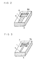
- Figs. 2 and 3 show perspective schematic views of microwave stripline resonators of other embodiments of the invention
- Fig. 4 shows a perspective schematic view of filter device employing a microwave stripline resonator of the invention
- Fig. 5 shows a perspective view of conventional microwave stripline resonator.
- a grounding electrode 3 As shown in Fig. 1, in which one of the embodiments of the present invention is illustrated, adjacent surfaces of a rectangular dielectric substrate 1 are covered by a grounding electrode 3. A surface 2 of dielectric substrate 1 is provided with a depression 4 which is covered by an electrode 4A. Electrode 4A is connected to grounding electrode 3 through a strip electrode 5. Strip electrode 5 has a width identical to that of electrode 4A.
- the total length of strip electrode 5 and electrode 4A covering depression 4 can be substantially shorter than the length of a stripline electrode of a conventional microwave stripline resonator.
- Fig. 2 shows another embodiment of the present invention, where the electrode length is made still shorter than that of the microwave stripline resonators shown in Fig. 1. This is accomplished by employing an electrode 6A which covers depression 4. Electrode 6A has a wider width than that of strip electrode 5 provided on the surface of dielectric substrate 1.
- Fig. 3 shows still another embodiment of the present invention providing a depression 7 which is covered by an electrode 7A with a U-shaped opening partly accommodating strip electrode 5.
- a filter device employing the microwave stripline resonator shown in Fig. 1, is illustrated in Fig. 4 wherein adjacent surfaces of rectangular dielectric substrate 1 (not including surface 2) are covered by a grounding electrode 3 by means of metallization or such, and two rectangular depressions 4 are provided on the surface 2 of said dielectric substrate 1.
- Electrodes 4A covering depressions 4 are connected to grounding electrode 3.
- Signal output electrodes 9 are also provided on regions corresponding to depressions 4 on the rear side 8 of dielectric substrate 1.
- a compact and high-performance microwave stripline resonator can be realized by providing depressions covered by electrodes and strip electrodes connected thereto on a dielectric substrate.
Landscapes
- Control Of Motors That Do Not Use Commutators (AREA)
Claims (3)
- Mikrowellen-Streifenleitungsresonator umfassend:ein rechteckiges dielektrisches Substrat (1), welches eine Vertiefung (4) auf einer ersten Fläche (2) des Substrats besitzt;eine Streifenelektrode (5), die auf der ersten Fläche (2) des dielektrischen Substrats (1) angeordnet ist;eine Masseelektrode (3), die auf einer zweiten Fläche des dielektrischen Substrats (1) angeordnet ist;eine Elektrode (4A, 6A, 7A), welche die Vertiefung (4) überdeckt,dadurch gekennzeichnet, daßdie Vertiefung (4) an einem ersten Ende der Streifenelektrode (5) angeordnet ist und die Masseelektrode (3) an einem zweiten Ende der Streifenelektrode (5) angeordnet ist und daßdie Elektrode (4A, 6A, 7A) die Vertiefung (4) bedeckt und daß die Masseelektrode (3) das erste und zweite Ende der Steifenelektrode (3) entsprechend verbindet derart, daß die Impedanz der Streifenelektrode (5) und diejenige der Elektrode (4A, 6A, 7A), welche die Vertiefung (4) bedeckt, verschieden sind.
- Mikrowellen-Streifenleitungsresonator nach Anspruch 1, worin die Breite der Vertiefung (4) größer ist als die Breite der Streifenelektrode (5).
- Mikrowellen-Streifenleitungsresonator nach Anspruch 1 oder 2, worin die Vertiefung (4) U-förmig ist, um sich teilweise an die Streifenelektrode (5) anzupassen.
Applications Claiming Priority (2)
| Application Number | Priority Date | Filing Date | Title |
|---|---|---|---|
| JP2180839A JPH0468901A (ja) | 1990-07-09 | 1990-07-09 | マイクロ波ストリップライン共振器 |
| JP180839/90 | 1990-07-09 |
Publications (3)
| Publication Number | Publication Date |
|---|---|
| EP0466069A2 EP0466069A2 (de) | 1992-01-15 |
| EP0466069A3 EP0466069A3 (en) | 1992-12-09 |
| EP0466069B1 true EP0466069B1 (de) | 1996-11-13 |
Family
ID=16090260
Family Applications (1)
| Application Number | Title | Priority Date | Filing Date |
|---|---|---|---|
| EP91111331A Expired - Lifetime EP0466069B1 (de) | 1990-07-09 | 1991-07-08 | Mikrowellenstreifenresonatoren |
Country Status (4)
| Country | Link |
|---|---|
| US (1) | US5162761A (de) |
| EP (1) | EP0466069B1 (de) |
| JP (1) | JPH0468901A (de) |
| DE (1) | DE69123092T2 (de) |
Families Citing this family (11)
| Publication number | Priority date | Publication date | Assignee | Title |
|---|---|---|---|---|
| US5293140A (en) * | 1991-01-02 | 1994-03-08 | Motorola, Inc. | Transmission line structure |
| JPH0529818A (ja) * | 1991-07-19 | 1993-02-05 | Matsushita Electric Ind Co Ltd | Temモード共振器 |
| FI90808C (fi) * | 1992-05-08 | 1994-03-25 | Lk Products Oy | Resonaattorirakenne |
| GB9216915D0 (en) * | 1992-08-10 | 1992-09-23 | Applied Radiation Lab | Improved radio frequency filter |
| JP3307044B2 (ja) * | 1993-12-24 | 2002-07-24 | 松下電器産業株式会社 | 誘電体共振器およびその入出力結合回路 |
| JP3331949B2 (ja) * | 1998-02-20 | 2002-10-07 | 株式会社村田製作所 | 誘電体フィルタ、誘電体デュプレクサおよび通信機装置 |
| KR100513709B1 (ko) * | 1999-03-31 | 2005-09-07 | 삼성전자주식회사 | 전압제어발진기의 위상 잡음 감소용 공동공진기 및 그 제작방법 |
| US6727785B2 (en) * | 2002-06-27 | 2004-04-27 | Harris Corporation | High efficiency single port resonant line |
| US6963259B2 (en) * | 2002-06-27 | 2005-11-08 | Harris Corporation | High efficiency resonant line |
| JP4535267B2 (ja) * | 2005-02-09 | 2010-09-01 | Tdk株式会社 | 電子部品 |
| TW200737586A (en) * | 2006-03-31 | 2007-10-01 | Hon Hai Prec Ind Co Ltd | Band-pass filter |
Family Cites Families (7)
| Publication number | Priority date | Publication date | Assignee | Title |
|---|---|---|---|---|
| GB1442383A (en) * | 1973-10-26 | 1976-07-14 | Secr Defence | Stripline components |
| US4266206A (en) * | 1978-08-31 | 1981-05-05 | Motorola, Inc. | Stripline filter device |
| JPS58103202A (ja) * | 1981-12-16 | 1983-06-20 | Fujitsu Ltd | 誘電体フイルタ |
| JPS59147913A (ja) * | 1983-02-14 | 1984-08-24 | Inax Corp | 熱交換装置 |
| JPS61161802A (ja) * | 1985-01-11 | 1986-07-22 | Mitsubishi Electric Corp | 高周波ろ波器 |
| JPS63316902A (ja) * | 1987-06-19 | 1988-12-26 | Murata Mfg Co Ltd | 共振器の共振周波数の調整方法 |
| US4785271A (en) * | 1987-11-24 | 1988-11-15 | Motorola, Inc. | Stripline filter with improved resonator structure |
-
1990
- 1990-07-09 JP JP2180839A patent/JPH0468901A/ja active Pending
-
1991
- 1991-07-08 DE DE69123092T patent/DE69123092T2/de not_active Expired - Fee Related
- 1991-07-08 EP EP91111331A patent/EP0466069B1/de not_active Expired - Lifetime
- 1991-07-09 US US07/727,417 patent/US5162761A/en not_active Expired - Fee Related
Also Published As
| Publication number | Publication date |
|---|---|
| US5162761A (en) | 1992-11-10 |
| DE69123092D1 (de) | 1996-12-19 |
| JPH0468901A (ja) | 1992-03-04 |
| DE69123092T2 (de) | 1997-03-06 |
| EP0466069A3 (en) | 1992-12-09 |
| EP0466069A2 (de) | 1992-01-15 |
Similar Documents
| Publication | Publication Date | Title |
|---|---|---|
| US6566986B2 (en) | Dielectric filter | |
| US5812036A (en) | Dielectric filter having intrinsic inter-resonator coupling | |
| EP0526643B1 (de) | Antennenanordnung | |
| US6052040A (en) | Dielectric duplexer with different capacitive coupling between antenna pad and transmitting and receiving sections | |
| EP0068504B1 (de) | Kammfilter | |
| WO2001013460A1 (en) | Microwave filter | |
| EP0537798B1 (de) | Mikrowellenfilter | |
| US6262640B1 (en) | Coplanar line filter and duplexer | |
| US6236288B1 (en) | Dielectric filter having at least one stepped resonator hole with a recessed or protruding portion, the stepped resonator hole extending from a mounting surface | |
| US5162761A (en) | Microwave stripline resonator including a dielectric substrate having a depression | |
| EP0959518B1 (de) | Dielektrisches Filter, dielektrischer Duplexer, und Sender-Empfänger | |
| KR100397732B1 (ko) | 유전체 필터, 듀플렉서 및 이를 포함하는 통신기 장치 | |
| US6060965A (en) | Dielectric resonator and filter including capacitor electrodes on a non-conductive surface | |
| US5559485A (en) | Dielectric resonator | |
| JPH11239006A (ja) | 誘電体フィルタ | |
| JP3428928B2 (ja) | 帯域内群遅延一定型誘電体フィルタとそれを用いた歪み補償型増幅器 | |
| CA2200279C (en) | Field effect transistor amplifier | |
| US5331300A (en) | Dielectric filter device | |
| JP2713335B2 (ja) | ダイオード移相器 | |
| JPH05191103A (ja) | 積層型誘電体フィルタ | |
| JPH1168407A (ja) | 誘電体フィルタ | |
| KR100258788B1 (ko) | 동축선 공진기의 절반구조를 이용한 대역 통과 여파기 | |
| JPH11274815A (ja) | 誘電体フィルタ | |
| JP3469476B2 (ja) | 誘電体フィルタ | |
| JPH06204702A (ja) | マイクロ波フィルタ |
Legal Events
| Date | Code | Title | Description |
|---|---|---|---|
| PUAI | Public reference made under article 153(3) epc to a published international application that has entered the european phase |
Free format text: ORIGINAL CODE: 0009012 |
|
| AK | Designated contracting states |
Kind code of ref document: A2 Designated state(s): DE GB |
|
| PUAL | Search report despatched |
Free format text: ORIGINAL CODE: 0009013 |
|
| AK | Designated contracting states |
Kind code of ref document: A3 Designated state(s): DE GB |
|
| 17P | Request for examination filed |
Effective date: 19930608 |
|
| 17Q | First examination report despatched |
Effective date: 19941227 |
|
| GRAG | Despatch of communication of intention to grant |
Free format text: ORIGINAL CODE: EPIDOS AGRA |
|
| GRAH | Despatch of communication of intention to grant a patent |
Free format text: ORIGINAL CODE: EPIDOS IGRA |
|
| GRAH | Despatch of communication of intention to grant a patent |
Free format text: ORIGINAL CODE: EPIDOS IGRA |
|
| GRAA | (expected) grant |
Free format text: ORIGINAL CODE: 0009210 |
|
| AK | Designated contracting states |
Kind code of ref document: B1 Designated state(s): DE GB |
|
| REF | Corresponds to: |
Ref document number: 69123092 Country of ref document: DE Date of ref document: 19961219 |
|
| PLBE | No opposition filed within time limit |
Free format text: ORIGINAL CODE: 0009261 |
|
| STAA | Information on the status of an ep patent application or granted ep patent |
Free format text: STATUS: NO OPPOSITION FILED WITHIN TIME LIMIT |
|
| 26N | No opposition filed | ||
| PGFP | Annual fee paid to national office [announced via postgrant information from national office to epo] |
Ref country code: DE Payment date: 20010702 Year of fee payment: 11 |
|
| PGFP | Annual fee paid to national office [announced via postgrant information from national office to epo] |
Ref country code: GB Payment date: 20010704 Year of fee payment: 11 |
|
| REG | Reference to a national code |
Ref country code: GB Ref legal event code: IF02 |
|
| PG25 | Lapsed in a contracting state [announced via postgrant information from national office to epo] |
Ref country code: GB Free format text: LAPSE BECAUSE OF NON-PAYMENT OF DUE FEES Effective date: 20020708 |
|
| PG25 | Lapsed in a contracting state [announced via postgrant information from national office to epo] |
Ref country code: DE Free format text: LAPSE BECAUSE OF NON-PAYMENT OF DUE FEES Effective date: 20030201 |
|
| GBPC | Gb: european patent ceased through non-payment of renewal fee |
Effective date: 20020708 |