EP0466330A2 - Méthode pour éditer des caractères matriciels de petites dimensions utilisant des séries connectées de pixels - Google Patents
Méthode pour éditer des caractères matriciels de petites dimensions utilisant des séries connectées de pixels Download PDFInfo
- Publication number
- EP0466330A2 EP0466330A2 EP91305195A EP91305195A EP0466330A2 EP 0466330 A2 EP0466330 A2 EP 0466330A2 EP 91305195 A EP91305195 A EP 91305195A EP 91305195 A EP91305195 A EP 91305195A EP 0466330 A2 EP0466330 A2 EP 0466330A2
- Authority
- EP
- European Patent Office
- Prior art keywords
- runs
- pixel
- character
- run
- pixels
- Prior art date
- Legal status (The legal status is an assumption and is not a legal conclusion. Google has not performed a legal analysis and makes no representation as to the accuracy of the status listed.)
- Granted
Links
Images


Classifications
-
- G—PHYSICS
- G09—EDUCATION; CRYPTOGRAPHY; DISPLAY; ADVERTISING; SEALS
- G09G—ARRANGEMENTS OR CIRCUITS FOR CONTROL OF INDICATING DEVICES USING STATIC MEANS TO PRESENT VARIABLE INFORMATION
- G09G5/00—Control arrangements or circuits for visual indicators common to cathode-ray tube indicators and other visual indicators
- G09G5/22—Control arrangements or circuits for visual indicators common to cathode-ray tube indicators and other visual indicators characterised by the display of characters or indicia using display control signals derived from coded signals representing the characters or indicia, e.g. with a character-code memory
- G09G5/24—Generation of individual character patterns
-
- G—PHYSICS
- G06—COMPUTING OR CALCULATING; COUNTING
- G06K—GRAPHICAL DATA READING; PRESENTATION OF DATA; RECORD CARRIERS; HANDLING RECORD CARRIERS
- G06K15/00—Arrangements for producing a permanent visual presentation of the output data, e.g. computer output printers
- G06K15/02—Arrangements for producing a permanent visual presentation of the output data, e.g. computer output printers using printers
-
- G—PHYSICS
- G06—COMPUTING OR CALCULATING; COUNTING
- G06K—GRAPHICAL DATA READING; PRESENTATION OF DATA; RECORD CARRIERS; HANDLING RECORD CARRIERS
- G06K2215/00—Arrangements for producing a permanent visual presentation of the output data
- G06K2215/0002—Handling the output data
- G06K2215/004—Generic data transformation
- G06K2215/0042—Rasterisation
- G06K2215/0045—Converting outline to bitmap
Definitions
- the current invention relates to an improved method of legibly displaying characters at low resolution.
- characters have been printed using metal type which allows very detailed rendering of a character, including subtle curves and very fine lines.
- a character may be alphanumeric, an Oriental or other foreign language character, or even a fanciful design and may be printed in a variety of point sizes.
- characters are defined on raster devices such as video display terminals or laser printers or by using a multi-pin print head. Characters can be printed on a surface or displayed on a video screen as a series of dots which are printed or turned on in order to approximate as closely as possible the ideal shape of the character.
- a typical video monitor can display about 72 pixels per inch. At this resolution it is difficult to display legibly most type faces smaller than about twenty pixels tall.
- a character is usually defined in "character space” at very high resolution as one or more areas bounded by an outline or path.
- a character consists of one or more continuous black areas.
- the letter “O” consists of a single closed loop
- the letter “d” consists of a loop connected to a line
- the letter “i” consists essentially of a dot a short distance away from a line which may have additional details such as serifs.
- One way of describing a character involves defining an outline of the outer edge of each contiguous black portion of the character and then filling that outline to display the character.
- the outline is preferably defined as one or more paths, each of which is usually traced in one direction, either clockwise or counter-clockwise. Each path can be represented as a sequential series of curves and/or linear line segments called edges. If a black area has interior white spaces as, for instance, in the letter "O", each interior white area can also be defined by a path consisting of a series of edges.
- the present invention details a method to detect and fix certain topological errors in character bitmaps by (1) enumerating runs of pixels in an order determined by the path topology, (2) searching for collisions, which are runs that improperly touch other runs in the character bitmap, and (3) cleaning up bitmap to fix such incorrect contacts.
- a character bit-map is "cleaned up" by identifying collisions where two runs touch but should not, then moving or deleting one or more pixels in order to display the character more legibly. This procedure is typically done after a character has been prepared for display using one or more fill methods such as the center point fill, horizontal proximity fill, connected run fill and X inflection fill described in the prior art. See, for example, United States Patent Application entitled “Connected-Run Drop Out-Free Center Point Fill Method for Displaying Characters" by the same inventors, filed on June 15, 1990.
- One object of the present invention is to modify the appearance of a character in order to make it more legible at small sizes.
- Another object of this invention is to provide a rapid method for such modification.
- Figure 1 illustrates pixel mapping of characters using a simple or modified center point fill method before using (1A, 1B, 1C) and after using (1D, 1E, 1F) the method of the present invention.
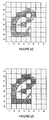
- Figures 2A, 2B, 2C and 2D in sequence illustrate pixel mapping of a character "e" using the method of the present invention.
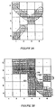
- FIG. 3 illustrates details of using the present invention.
- a character can be represented by a series of filled areas which contrast with the background.
- the filled areas will be referred to as black areas, as in ink printed on a page, but the area can be filled by many methods well known to those skilled in the art.
- pixels in black areas and runs of pixels are described as "displayed” but the method actually selects pixels for subsequent display using a desired fill method. A complete black fill is presumed for purposes of this specification, and all selected pixels are displayed.
- each black area can be defined by a closed path consisting of sequential series of curves or linear line segments called edges.
- the interior of a character can be distinguished from the background by drawing a line from a point in any direction past the greatest extent of the character and counting the number of intersections with the path. If the number of intersections is odd, the point is inside the character and if the number is even the point is outside.
- characters which have enclosed white spaces such as the character "O” will have at least one additional path consisting of a series of edges to define each enclosed space.
- a character may contain more than one black area such as the letter "i" or many oriental characters.
- Such dropouts can be detected by identifying black portions of a character that cross a horizontal midline but do not include a pixel center. They can be corrected by displaying the pixel closest to an edge along that horizontal midline.
- Methods of performing the horizontal proximity fill test are described in United States Patent Application 07-388,336 filed August 1, 1989 and assigned to the same assignee as the subject application; and in "Connected-Run Dropout-Free Center Point Fill Method For Displaying Characters" filed on June 15, 1990 by the inventors of the subject invention and also assigned to the same assignee. The latter application also describes two additional fill methods, connected run fill and X extreme fill.
- the character is scaled to fit a pixel grid for the desired display space and curves are flattened to a series of connected, linear edges in order along a path.
- a path is traced in one direction (clockwise or counter-clockwise) and crosses are identified as points where edges cross a horizontal midline through pixel centers. If an end point of an edge happens to lie directly on a horizontal midline, the end point is moved up or down slightly so that no edge end points are crosses. The crosses are stored in a path list in path order.
- Edge end points which are X extremes are also identified.
- edge endpoints which are Y extremes are also identified and the crosses and X and Y extremes are included in the same path list.
- One skilled in the art may choose to include additional end points in the path list to represent the path more accurately.
- horizontal scan line D includes a cross pair in pixel D2 and a second cross pair with crosses in pixels D3 and D4 .
- the goal of this display method is to determine a run of one or more horizontally adjacent pixels for each cross pair and then to modify runs or add runs if needed in order to display the character as a series of connected runs. Runs can be described for convenience by the starting and ending pixel, e.g., B2-B2 or B3-B4 .
- each cross pair is tested and where a center point of a pixel such as pixels D2 or D3 falls within a cross pair or intersects a cross, that pixel is displayed. This results in most cross pairs being displayed as runs.
- a cross pair is located between two adjacent pixel centers such as in pixels E5 and E6 in Figure 2A
- the preferred implementation determines the midpoint between the cross pair and displays a run of one pixel for that cross pair, the pixel containing that midpoint (the pixel having a center closest to the midpoint). This process is called horizontal proximity fill.
- each cross pair is displayed by a run of at least one pixel.
- the horizontal proximity fill method will not catch certain dropouts where a black section of the character intersects a vertical midline without intersecting a pixel center.
- United States Patent Application 07-388,336 describes methods including using a variation of the horizontal proximity fill test to correct such dropouts. In the preferred implementation, those dropouts are corrected by connected run fill and X extreme fill as described in detail in copending application "Connected-Run Dropout-Free Center Point Fill Method for Displaying Characters" by the same inventors and filed on June 15, 1990.
- each cross pair is compared to each adjacent cross pair and the runs associated with adjacent cross pairs are tested to see if they are properly connected, that is, making pixel-to-pixel contact along a pixel edge or at a pixel corner.
- Adjacent cross pairs are identified by tracing the path associated with each cross of the pair, identifying the preceding and subsequent cross along each path and finding the cross pair for each of those crosses. Runs associated with adjacent cross pairs are called adjacent runs.
- cross pair 114-103 has two adjacent cross pairs. Cross 114 is followed in path order (based on a clockwise path) by cross 101 , which is part of cross pair 101-102 , and preceded by cross 113 , which is part of cross pair 104-113 .
- Cross 103 is followed by cross 104 and preceded by cross 102 , so cross pair 114-103 has two adjacent cross pairs, 101-102 and 104-113 .
- Cross pair 101-102 has only one adjacent cross pair.
- Cross pairs may be tested in many possible orders. In the preferred form of the invention the scan lines are examined in order and each cross pair is tested in the order it is encountered. One skilled in the art will recognize that looking in only one vertical direction and only one horizontal direction will avoid duplicate testing of the same two adjacent cross pairs.
- cross pairs can be examined, for example, by following character features from one Y extreme to the next. Each cross pair is tested for proper connection against adjacent cross pairs that are up from or to the right of the cross pair being tested.
- the first cross pair is 104-113 on scan line B , which is tested against the upper, adjacent cross pair in pixels C1 and C2 and against the right, adjacent cross pair 114-103 .
- the run displaying the current cross pair is tested to see if it is connected to runs displaying adjacent cross pairs. Two runs are connected if at least one pixel in one run shares an edge or corner with one pixel in the other run. In the preferred implementation, pixels are considered square but one skilled in the art will recognize how to test runs of pixels which are not square.
- Two adjacent runs in the same scan line but separated by one or more non-displayed pixels may still be connected by a continuous portion of the character.
- two such adjacent runs are considered connected if runs "neighboring" those runs complete a connection between them.
- Two runs are neighbor runs if a curve can be drawn between a cross of the cross pair for one run and a cross of the cross pair of the second run without crossing a path or a horizontal midline.
- adjacent runs E2-E2 (for cross pair 14-15 where the center of pixel E2 is within the cross pair) and E5-E5 (for cross pair 16-17 ) are not connected directly but both are connected through neighbor runs F1-F3 (a line can be drawn from e.g. cross 10 to cross 17 or cross 14 without crossing a horizontal midline or a path) and F4-F5 . Otherwise a dropout is noted and repaired using the method described below.
- Dropouts are fixed by extending existing runs or creating new runs. To connect runs that are not properly connected, two scan lines are examined and the intersections, called vertical intersections, between any path and the vertical midline through the column including each dropped-out pixel are identified. The intersections in each column are placed in order vertically, and one or more appropriate pixels containing vertical midpoints are displayed by extending existing runs or adding new runs, as needed.
- Two adjacent scan lines must be selected and analyzed in order to fix dropouts.
- a dropout could occur between two runs in the same scan line or between two runs in adjacent scan lines. If the dropout occurs between runs on adjacent scan line, the following test is performed using those two scan lines. If the dropout occurs between runs on the same scan line, any path that connects the runs necessarily goes above or below the horizontal midline of that scan line. By testing the path between the innermost crosses, that direction is determined and the scan line containing the cross pairs and the adjacent scan line in the direction indicated by the path are examined using the following test. For example, in Figure 2A, the path between cross pairs 105-111 and 110-108 goes up at each of crosses 105, 111, 110 and 108 so the current and upper scan lines, F and G , are selected as of interest and tested as described below.
- Every path segment between crosses in the scan lines of interest is traced, noting any vertical intersections with the vertical midline through each column containing a dropped-out pixel.
- the highest intersection along the lowest path and the lowest intersection along the highest path are taken as intersections of particular interest, the midpoint of those two intersections is found, and the pixel containing that midpoint is selected for display, applying an arbitration test if necessary, e.g. if the midpoint fell on a pixel boundary.
- new crosses or pseudocrosses are defined and paired.
- the pseudocrosses should be on the horizontal midline through a pixel to be displayed and should not overlap an existing cross pair.
- pseudocrosses are created on the horizontal midline of a pixel to be displayed, on alternate sides of the vertical midline of that pixel, less than half a pixel-unit from and preferably relatively close to the vertical midline. If this placement overlaps an existing cross pair, the position of the pseudocross pair is adjusted to avoid the overlap.
- the pseudocross pair is included in scan line order to display a run including the new pixel.
- a run of more than one pixel to be displayed can be marked with a single pseudocross pair.
- a complex figure may require more than one pseudocross pair to fix and display dropouts.
- the new pseudocrosses are included in path order for the character as described below.
- Certain characters include narrow horizontal features which may not be easily displayed at low resolution by using only the fill methods described above.
- the scaled character that is, scaled to the pixel grid of the desired display space, is examined to identify (horizontal) X extremes -- points where delta X changes sign.
- Delta X is the change in X from point to point along the path and changes sign whenever X hits a local horizontal maximum or minimum and then begins to move in the opposite direction.
- An X extreme is also marked when delta X becomes 0 or when delta X ceases to be 0, which corresponds to the top and bottom points of a vertical feature.
- An X extreme does not have to include a dramatic feature, however.
- the character in Figure 2A includes maximum X extremes 130, 131 and 132 in pixels D5 and F6(two) , respectively and minimum X extremes 133 , 134 and 135 in pixels D3 , C1 and C2 , respectively.
- X extremes are identified in the pass when crosses are identified and the extremes are stored in a separate list in path order. In the preferred implementation, the extremes were included in the list of edge end points and crosses.
- each extreme is tested for proper connection to a displayed run.
- the path through each extreme is traced forward and backward to identify the closest adjacent run, in path order. If the extreme is within one-half pixel distance of an adjacent run, no further processing is required and the extreme is ignored.
- the remaining extremes are analyzed by tracing the path forward and backward from the extreme to the closest cross pair in each direction and identifying intersections with vertical midlines between the closest adjacent run and the extreme. As described for the connected run dropout fill described above, the vertical intersections in each column are ordered, midpoints are identified, and one or more pixels are displayed by extending existing runs and/or creating pseudocross pairs and adding new runs.
- This invention requires more restrictive handling of fixing dropouts than the previous invention.
- the previous invention allowed dropouts to be fixed by extending any existing run or creating pseudocrosses which were not necessarily part of the outline.
- This invention requires that each run be connected to all its neighbor runs, that is, drop-outs must be fixed by extending (or creating) only neighbor runs. Extending runs to fix a dropout is done using the same method as the previous invention except only neighbor runs are eligible, not all runs.
- a new cross pair must be created using the same method as the creation of a pseudocrosses in the previous invention.
- the path must be modified with a new vertical excursion which includes the new cross pair, and it must be done so that the new cross pair is a neighbor run to the original runs with the dropout.
- a vertical excursion is added into the path segment that connects the two original runs, or included with a path segment that connects neighbor runs.
- a collision is an undesirable touch between two runs which are not neighbor runs. Collisions are identified by three different methods.
- the first method checks for runs on the same scan line that are touching on one edge.
- “touching” means that two runs share a common pixel edge (an edge touch) or contact each other at a pixel corner (a corner touch).
- run D2-D2 and run D3-D4 constitute a collision because they touch at the pixel edge between pixels D2 and D3 .
- the second method for finding collisions finds all path segments between two crosses in path order where (a) both crosses are on the same scan line and (b) the leftmost of the two crosses is the leftmost cross of its cross pair and the rightmost of the two crosses is the rightmost cross of its cross pair.
- crosses 101 and 102 in pixel C5 are adjacent in path order and fit the criteria of this test.
- Cross 104 in pixel B2 and cross 103 in pixel B4 also meet this criteria.
- There are one or two runs of interest If both of the crosses are in the same cross pair, the single run of interest is the run displaying that cross pair. If both crosses are not in the same cross pair, then there are two runs of interest. These are the two runs which display each of the cross pairs respectively containing each of the crosses.
- the third method of identifying collisions checks the connectivity of white areas between runs. These areas can be considered “white runs” which display "white cross pairs" which can easily be determined using the scan row list of crosses. This procedure compares white runs on one line against white runs on adjacent scan lines in which the corresponding white cross pairs are adjacent on a path. The white runs are connected if they share at least one edge. In the preferred implementation, common corners between white runs are not sufficient to connect the white runs. The runs bounding the white runs are examined and any two runs which are not adjacent on a path but touch and are also horizontally adjacent to adjacent white runs are said to collide. For example, white run E3-E4 and white run F5-F5 are adjacent in path order but they do not share a common pixel edge.
- Cross 110 in pixel F6 is adjacent to cross 109 in pixel E5; crosses 111 and 112 are adjacent to each other.
- Run F3-F4 is horizontally adjacent to white run F5-F5 and run E5-E5 is horizontally adjacent to white run E3-E4 . Since runs F3-F4 and E5-E5 are not adjacent but touch at a corner, those runs create a collision.
- trespasser runs The configuration of the two trespasser runs and the sets of neighbor runs for each trespasser run is used to determine the repair operation(s) to try.
- Repair operations consist of moving or deleting pixels in one or both trespasser runs. Repair operations must never sever connections between neighbor runs. For many configurations, there will be a number of different acceptable repair operations. It may be necessary to try more than one repair operation for a particular collision in a character, since the first operation that is tried may fail. For instance, moving a pixel up may cause another collision with another run, while deleting the pixel may repair the collision without creating other collisions.
- the preferred implementation of this invention is limited to collisions between single pixels which do not overlap. Covered configurations include:
- each collision has a pair of trespassers. Displayed pixels which are included in neighbor runs and share an edge or corner with a trespasser are called “neighbors" of that trespasser. Pixels which are deleted by the clean-up method of this invention are still considered to be neighbors even though they are no longer displayed so as to avoid introducing additional distortion in a character. See Example 2 below.
- the locations of neighbor pixels and the other trespasser of the pair are mapped into a 3 x 3 matrix called the "neighbor matrix".
- Operations which may be performed on the trespasser being analyzed which will repair the collision are selected for each matrix and given a relative "merit" value according to a set of guidelines given below.
- the basic operations possible are deleting the trespasser or moving it. A move could be in one of many directions, preferably up, down or sideways.
- the merit value is used to decide the order in which operations are tried.
- the selected operations are stored along with the corresponding relative merit value in a database or look up table.
- each trespasser is independent of the neighbors of the corresponding trespasser of the pair.
- One skilled in the art will recognize that there are ways to optimize this stored information, for instance, by leaving out matrices that have no selected operations, and by storing only certain rotations of matrices.
- run D2-D2 touches run D3-D4 .
- Pixels D2 and D3 are touching on an edge so they are trespassers.
- Pixel D2 has neighbors E2 and C2 so the neighbor matrix for pixel D2 looks like: where the trespasser of interest is represented by an "x" centered in the matrix, its neighbors are also represented by x's, the other trespasser ( D3 ) is represented by a "t", and other pixels (displayed or not) are represented by a " . ".
- the neighbor matrix looks like:
- Run D4-D4 (updated by the preceding repair) and run C5-C5 also collide at the corner.
- the trespassers are D4 and C5 .
- the corresponding neighbor matrices are: Note that pixel D3 is a neighbor of D4 even though pixel D3 was deleted in the previous repair.
- the neighbor matrix for D4 produces one operation: a "move-up" operation which has a high merit since it is a move.
- the neighbor matrix for C5 produces two operations: move down (high merit) and delete (low merit).
- the C5 move operation has higher merit than the D4 move operation because D4 is in the middle of the feature while C5 is at the end.
- the operation "move C5 down” is attempted and does not cause other collisions. Therefore, the chosen repair, shown in Figure 2C, moves C5 down, thus deleting run C5-C5 and extending run B2-B4 to B2-B5 .
- the third detection method finds a corner collision between runs F3-F4 and run E5-E5 .
- the trespassers are pixels F4 and E5 .
- the neighbor matrices are: The F4 neighbor matrix allows a "move up” operation of high merit.
- the E5 neighbor matrix allows no operations. The operation "move F4 up” does not cause other collisions so F4 is moved up, as shown in Figure 2D, updating run F3-F4 to F3-F3 and extending run G5-G5 to become G4-G5 .
- runs D3-D3 and C2-C2 collided and pixels D3 and C2 were trespassers.
- the neighbor matrices were: Looking up these neighbor matrices in the database, trespasser C2 could be moved left or down. Both move operations had the same merit--there was nothing in the matrix to dictate which to choose. Each of these move operations had a high merit. Trespasser C2 could also be deleted, which had a merit lower than any move operation but relatively high for a delete.
- Trespasser D3 could not be deleted because it maintained a connection between E2 and E4 . It could be moved up. This operation had a medium merit because (a) moves were better than deletes, but (b) it was likely that changing the curve outline feature to a straight feature will change the appearance of the character. Complete analysis yielded four operations which were ranked by relative merit.
- FIG. 3B This example illustrates the benefit of including deleted pixels in the neighbor matrix even though they were not displayed.
- pixel C4 was displayed by two overlapping runs, both designated C4-C4 .
- One run was for cross pair 121-122 and the other was for cross pair 123-124 .
- Each of these runs collide with pixel D4 .
- Both runs for 121-122 and for 123-124 had the same neighbor matrix although this is not necessarily true for all overlapping runs.
- the trespassers were C4 and D4 .
- the neighbor matrices were:
- Trespasser D4 could not be deleted or moved according to the rules of the preferred implementation (deletion would create a "nick" in the feature and no moves were possible).
- Trespasser C4 could be deleted from both runs displaying that pixel, so C4 was deleted. This result is proper for the run for 121-122 as well as for the run for 123-124 because the neighbor matrix is the same.
- the cross pairs were maintained in path order although no longer displayed by any pixel.
- runs B5-B5 and C6-C6 also constitute a collision, with trespassers B5 and C6 .
- the neighbor matrices were:
- Pixel C4 which was deleted in the previous step, was ignored when calculating the neighbor matrix for pixel B5 , the character could become unduly distorted.
- Pixel C4 is represented in the neighbor matrix for B5 by "(x)", above.
- Trespasser C6 had no neighbors so it could not be moved or deleted.
- Pixel B5 could not be deleted or moved (either operation would sever the connection between C4 and A6 ). No operation was allowed and both pixels B5 and C6 remained displayed. If pixel C4 were not included in the neighbors of B5 , B5 could have been deleted thus severing the connected path from A6 to B4 .
Landscapes
- Engineering & Computer Science (AREA)
- Physics & Mathematics (AREA)
- General Physics & Mathematics (AREA)
- Theoretical Computer Science (AREA)
- General Engineering & Computer Science (AREA)
- Computer Hardware Design (AREA)
- Controls And Circuits For Display Device (AREA)
- Dot-Matrix Printers And Others (AREA)
- Image Processing (AREA)
- Document Processing Apparatus (AREA)
Applications Claiming Priority (2)
| Application Number | Priority Date | Filing Date | Title |
|---|---|---|---|
| US55278890A | 1990-07-13 | 1990-07-13 | |
| US552788 | 1990-07-13 |
Publications (3)
| Publication Number | Publication Date |
|---|---|
| EP0466330A2 true EP0466330A2 (fr) | 1992-01-15 |
| EP0466330A3 EP0466330A3 (en) | 1993-07-28 |
| EP0466330B1 EP0466330B1 (fr) | 1996-10-30 |
Family
ID=24206809
Family Applications (1)
| Application Number | Title | Priority Date | Filing Date |
|---|---|---|---|
| EP19910305195 Expired - Lifetime EP0466330B1 (fr) | 1990-07-13 | 1991-06-10 | Méthode pour éditer des caractères matriciels de petites dimensions utilisant des séries connectées de pixels |
Country Status (4)
| Country | Link |
|---|---|
| EP (1) | EP0466330B1 (fr) |
| JP (1) | JP3471817B2 (fr) |
| CA (1) | CA2044442A1 (fr) |
| DE (1) | DE69122915T2 (fr) |
Cited By (3)
| Publication number | Priority date | Publication date | Assignee | Title |
|---|---|---|---|---|
| WO2005066885A1 (fr) * | 2003-12-24 | 2005-07-21 | Eastman Kodak Company | Systeme d'impression, processus et produits avec micro impression |
| CN101814286A (zh) * | 2010-04-14 | 2010-08-25 | 深圳市茁壮网络股份有限公司 | 阿拉伯字符显示的修复方法及装置 |
| CN107077758A (zh) * | 2014-11-06 | 2017-08-18 | 英特尔公司 | 零覆盖光栅化剔除 |
Families Citing this family (1)
| Publication number | Priority date | Publication date | Assignee | Title |
|---|---|---|---|---|
| JP3979162B2 (ja) | 2002-04-22 | 2007-09-19 | ソニー株式会社 | 画像処理装置およびその方法 |
Family Cites Families (1)
| Publication number | Priority date | Publication date | Assignee | Title |
|---|---|---|---|---|
| JPS60116464A (ja) * | 1983-11-30 | 1985-06-22 | Toshiba Corp | プリンタ |
-
1991
- 1991-06-10 DE DE1991622915 patent/DE69122915T2/de not_active Expired - Lifetime
- 1991-06-10 EP EP19910305195 patent/EP0466330B1/fr not_active Expired - Lifetime
- 1991-06-12 CA CA 2044442 patent/CA2044442A1/fr not_active Abandoned
- 1991-07-10 JP JP19507291A patent/JP3471817B2/ja not_active Expired - Lifetime
Cited By (4)
| Publication number | Priority date | Publication date | Assignee | Title |
|---|---|---|---|---|
| WO2005066885A1 (fr) * | 2003-12-24 | 2005-07-21 | Eastman Kodak Company | Systeme d'impression, processus et produits avec micro impression |
| CN101814286A (zh) * | 2010-04-14 | 2010-08-25 | 深圳市茁壮网络股份有限公司 | 阿拉伯字符显示的修复方法及装置 |
| CN107077758A (zh) * | 2014-11-06 | 2017-08-18 | 英特尔公司 | 零覆盖光栅化剔除 |
| CN107077758B (zh) * | 2014-11-06 | 2021-08-24 | 英特尔公司 | 零覆盖光栅化剔除 |
Also Published As
| Publication number | Publication date |
|---|---|
| EP0466330B1 (fr) | 1996-10-30 |
| DE69122915D1 (de) | 1996-12-05 |
| JPH0535250A (ja) | 1993-02-12 |
| DE69122915T2 (de) | 1997-02-27 |
| EP0466330A3 (en) | 1993-07-28 |
| CA2044442A1 (fr) | 1992-01-14 |
| JP3471817B2 (ja) | 2003-12-02 |
Similar Documents
| Publication | Publication Date | Title |
|---|---|---|
| US5255357A (en) | Method for editing character bit maps at small sizes using connected runs | |
| JP2536966B2 (ja) | テキスト編集システム | |
| JP3748172B2 (ja) | 画像処理装置 | |
| US5099435A (en) | Method and apparatus for conversion of outline characters to bitmap characters | |
| RU2258265C2 (ru) | Автоматическая оптимизация расположения ножек символов текста | |
| KR0124961B1 (ko) | 문자 생성 방법 및 그 장치 | |
| US6496191B2 (en) | Method and apparatus for character font generation within limitation of character output media and computer readable storage medium storing character font generation program | |
| GB2354925A (en) | Image filling method, apparatus and computer readable medium for reducing filling process in producing animation | |
| JPS61138378A (ja) | ラスタ・ディスプレイ・システムにおける閉領域の探知及び充填方法 | |
| JP3637925B2 (ja) | 写真複写機用の単光路走査によるマーカで囲まれた領域の検出装置及び方法 | |
| US5200740A (en) | Dropout-free center point fill method for displaying characters | |
| JP2952673B2 (ja) | 関心領域抽出方法及び切り出し方法 | |
| EP0466330B1 (fr) | Méthode pour éditer des caractères matriciels de petites dimensions utilisant des séries connectées de pixels | |
| US5233336A (en) | Connected-run dropout-free center point fill method for displaying characters | |
| US5068803A (en) | Method and apparatus for filling contours in digital typefaces | |
| JP2681367B2 (ja) | 図形処理方法及びその装置 | |
| US5237313A (en) | Method for editing character bitmaps at small sizes | |
| JP4149464B2 (ja) | 画像処理装置 | |
| US4656468A (en) | Pattern data processing apparatus | |
| EP0411739B1 (fr) | Méthode d'édition des tableaux pour les éléments d'image sur écran des caractères à grandeurs minimes | |
| JPH0668271A (ja) | 画像処理装置 | |
| US5579460A (en) | Paint-out method and apparatus | |
| JPH07254065A (ja) | 画像検出装置および方法 | |
| JPH06119486A (ja) | 文字認識装置および表示方法 | |
| JPH07319444A (ja) | アウトライン文字描画方法 |
Legal Events
| Date | Code | Title | Description |
|---|---|---|---|
| PUAI | Public reference made under article 153(3) epc to a published international application that has entered the european phase |
Free format text: ORIGINAL CODE: 0009012 |
|
| AK | Designated contracting states |
Kind code of ref document: A2 Designated state(s): DE FR GB IT NL SE |
|
| PUAL | Search report despatched |
Free format text: ORIGINAL CODE: 0009013 |
|
| AK | Designated contracting states |
Kind code of ref document: A3 Designated state(s): DE FR GB IT NL SE |
|
| RHK1 | Main classification (correction) |
Ipc: G09G 5/24 |
|
| 17P | Request for examination filed |
Effective date: 19931125 |
|
| 17Q | First examination report despatched |
Effective date: 19941013 |
|
| GRAG | Despatch of communication of intention to grant |
Free format text: ORIGINAL CODE: EPIDOS AGRA |
|
| GRAH | Despatch of communication of intention to grant a patent |
Free format text: ORIGINAL CODE: EPIDOS IGRA |
|
| GRAH | Despatch of communication of intention to grant a patent |
Free format text: ORIGINAL CODE: EPIDOS IGRA |
|
| GRAA | (expected) grant |
Free format text: ORIGINAL CODE: 0009210 |
|
| AK | Designated contracting states |
Kind code of ref document: B1 Designated state(s): DE FR GB IT NL SE |
|
| PG25 | Lapsed in a contracting state [announced via postgrant information from national office to epo] |
Ref country code: NL Free format text: LAPSE BECAUSE OF FAILURE TO SUBMIT A TRANSLATION OF THE DESCRIPTION OR TO PAY THE FEE WITHIN THE PRESCRIBED TIME-LIMIT Effective date: 19961030 |
|
| REF | Corresponds to: |
Ref document number: 69122915 Country of ref document: DE Date of ref document: 19961205 |
|
| ET | Fr: translation filed | ||
| ITF | It: translation for a ep patent filed | ||
| PG25 | Lapsed in a contracting state [announced via postgrant information from national office to epo] |
Ref country code: SE Effective date: 19970130 |
|
| NLV1 | Nl: lapsed or annulled due to failure to fulfill the requirements of art. 29p and 29m of the patents act | ||
| PLBE | No opposition filed within time limit |
Free format text: ORIGINAL CODE: 0009261 |
|
| STAA | Information on the status of an ep patent application or granted ep patent |
Free format text: STATUS: NO OPPOSITION FILED WITHIN TIME LIMIT |
|
| 26N | No opposition filed | ||
| PGFP | Annual fee paid to national office [announced via postgrant information from national office to epo] |
Ref country code: FR Payment date: 20000601 Year of fee payment: 10 |
|
| PGFP | Annual fee paid to national office [announced via postgrant information from national office to epo] |
Ref country code: GB Payment date: 20000602 Year of fee payment: 10 |
|
| PG25 | Lapsed in a contracting state [announced via postgrant information from national office to epo] |
Ref country code: GB Free format text: LAPSE BECAUSE OF NON-PAYMENT OF DUE FEES Effective date: 20010610 |
|
| GBPC | Gb: european patent ceased through non-payment of renewal fee |
Effective date: 20010610 |
|
| PG25 | Lapsed in a contracting state [announced via postgrant information from national office to epo] |
Ref country code: FR Free format text: LAPSE BECAUSE OF NON-PAYMENT OF DUE FEES Effective date: 20020228 |
|
| PG25 | Lapsed in a contracting state [announced via postgrant information from national office to epo] |
Ref country code: IT Free format text: LAPSE BECAUSE OF NON-PAYMENT OF DUE FEES Effective date: 20050610 |
|
| PGFP | Annual fee paid to national office [announced via postgrant information from national office to epo] |
Ref country code: DE Payment date: 20100602 Year of fee payment: 20 |
|
| REG | Reference to a national code |
Ref country code: DE Ref legal event code: R071 Ref document number: 69122915 Country of ref document: DE |
|
| REG | Reference to a national code |
Ref country code: DE Ref legal event code: R071 Ref document number: 69122915 Country of ref document: DE |
|
| PG25 | Lapsed in a contracting state [announced via postgrant information from national office to epo] |
Ref country code: DE Free format text: LAPSE BECAUSE OF EXPIRATION OF PROTECTION Effective date: 20110611 |