EP0466371B1 - Raccord de tuyau - Google Patents
Raccord de tuyau Download PDFInfo
- Publication number
- EP0466371B1 EP0466371B1 EP91305879A EP91305879A EP0466371B1 EP 0466371 B1 EP0466371 B1 EP 0466371B1 EP 91305879 A EP91305879 A EP 91305879A EP 91305879 A EP91305879 A EP 91305879A EP 0466371 B1 EP0466371 B1 EP 0466371B1
- Authority
- EP
- European Patent Office
- Prior art keywords
- sealing
- joint structure
- gasket
- structure according
- face
- Prior art date
- Legal status (The legal status is an assumption and is not a legal conclusion. Google has not performed a legal analysis and makes no representation as to the accuracy of the status listed.)
- Expired - Lifetime
Links
- 230000008878 coupling Effects 0.000 title claims description 35
- 238000010168 coupling process Methods 0.000 title claims description 35
- 238000005859 coupling reaction Methods 0.000 title claims description 35
- 238000007789 sealing Methods 0.000 claims description 59
- 230000035515 penetration Effects 0.000 claims description 12
- 239000002184 metal Substances 0.000 claims description 9
- 230000006835 compression Effects 0.000 claims description 2
- 238000007906 compression Methods 0.000 claims description 2
- 230000007704 transition Effects 0.000 claims description 2
- 239000011324 bead Substances 0.000 description 6
- 239000012530 fluid Substances 0.000 description 2
- 230000005540 biological transmission Effects 0.000 description 1
- 230000015572 biosynthetic process Effects 0.000 description 1
- 238000010276 construction Methods 0.000 description 1
- 239000000463 material Substances 0.000 description 1
- 239000002245 particle Substances 0.000 description 1
- 230000000717 retained effect Effects 0.000 description 1
Images

Classifications
-
- F—MECHANICAL ENGINEERING; LIGHTING; HEATING; WEAPONS; BLASTING
- F16—ENGINEERING ELEMENTS AND UNITS; GENERAL MEASURES FOR PRODUCING AND MAINTAINING EFFECTIVE FUNCTIONING OF MACHINES OR INSTALLATIONS; THERMAL INSULATION IN GENERAL
- F16L—PIPES; JOINTS OR FITTINGS FOR PIPES; SUPPORTS FOR PIPES, CABLES OR PROTECTIVE TUBING; MEANS FOR THERMAL INSULATION IN GENERAL
- F16L21/00—Joints with sleeve or socket
-
- F—MECHANICAL ENGINEERING; LIGHTING; HEATING; WEAPONS; BLASTING
- F16—ENGINEERING ELEMENTS AND UNITS; GENERAL MEASURES FOR PRODUCING AND MAINTAINING EFFECTIVE FUNCTIONING OF MACHINES OR INSTALLATIONS; THERMAL INSULATION IN GENERAL
- F16L—PIPES; JOINTS OR FITTINGS FOR PIPES; SUPPORTS FOR PIPES, CABLES OR PROTECTIVE TUBING; MEANS FOR THERMAL INSULATION IN GENERAL
- F16L19/00—Joints in which sealing surfaces are pressed together by means of a member, e.g. a swivel nut, screwed on, or into, one of the joint parts
- F16L19/02—Pipe ends provided with collars or flanges, integral with the pipe or not, pressed together by a screwed member
- F16L19/025—Pipe ends provided with collars or flanges, integral with the pipe or not, pressed together by a screwed member the pipe ends having integral collars or flanges
-
- F—MECHANICAL ENGINEERING; LIGHTING; HEATING; WEAPONS; BLASTING
- F16—ENGINEERING ELEMENTS AND UNITS; GENERAL MEASURES FOR PRODUCING AND MAINTAINING EFFECTIVE FUNCTIONING OF MACHINES OR INSTALLATIONS; THERMAL INSULATION IN GENERAL
- F16L—PIPES; JOINTS OR FITTINGS FOR PIPES; SUPPORTS FOR PIPES, CABLES OR PROTECTIVE TUBING; MEANS FOR THERMAL INSULATION IN GENERAL
- F16L19/00—Joints in which sealing surfaces are pressed together by means of a member, e.g. a swivel nut, screwed on, or into, one of the joint parts
- F16L19/02—Pipe ends provided with collars or flanges, integral with the pipe or not, pressed together by a screwed member
- F16L19/0212—Pipe ends provided with collars or flanges, integral with the pipe or not, pressed together by a screwed member using specially adapted sealing means
- F16L19/0218—Pipe ends provided with collars or flanges, integral with the pipe or not, pressed together by a screwed member using specially adapted sealing means comprising only sealing rings
-
- Y—GENERAL TAGGING OF NEW TECHNOLOGICAL DEVELOPMENTS; GENERAL TAGGING OF CROSS-SECTIONAL TECHNOLOGIES SPANNING OVER SEVERAL SECTIONS OF THE IPC; TECHNICAL SUBJECTS COVERED BY FORMER USPC CROSS-REFERENCE ART COLLECTIONS [XRACs] AND DIGESTS
- Y10—TECHNICAL SUBJECTS COVERED BY FORMER USPC
- Y10S—TECHNICAL SUBJECTS COVERED BY FORMER USPC CROSS-REFERENCE ART COLLECTIONS [XRACs] AND DIGESTS
- Y10S285/00—Pipe joints or couplings
- Y10S285/917—Metallic seals
Definitions
- the invention relates to tube or pipe joints and couplings and, more particularly , to a metal gasket or seal coupling arrangement.
- the invention is especially suited for use in high vacuum systems and will be described with reference thereto; however, the invention could be used in a variety of types of pressure and vacuum systems.
- the typical coupling used in vacuum systems comprises opposed flanges with axially extending circumferential beads or protuberances arranged to engage with the opposite faces of a thin metallic gasket (US-A-3 521 910).
- a thin metallic gasket US-A-3 521 910
- the flanges are driven axially together causing the beads to penetrate the gasket and form seals therewith.
- the degree of bead penetration must be relatively closely controlled to produce a good seal. For example, if penetration is inadequate, an effective seal is not produced. Similarly, if penetration is too deep, it is possible to cut through the gasket and totally lose the seal.
- An object of the invention is to overcome the above-discussed problems and to provide an improved coupling or joint structure assembly especially suited for use in vacuum systems.
- WO-A-89/03495 discloses in Fig. 4 a joint structure especially suited for vacuum systems and of the kind comprising; a pair of flange components adapted for relative movement towards each other along a longitudinal axis, each of the flange components having an end face normal to the longitudinal axis; and a metal gasket positioned normal to the longitudinal axis between the end faces of the flange components, each of the end faces having a circumferentially continuous sealing protrusion for engaging the gasket with the protrusions being positioned in aligned opposed relationship at opposite sides of the gasket, and each of the end faces also having a flange face surface to constitute a stop surface for limiting penetration of said sealing protrusions into said gasket, each of said sealing protrusions being located at a distance (d) axially proud of the portion of the respective stop surface which is radially closest to the sealing protrusion.
- the sealing protrusions are in the form of sealing beads and the metal gasket has on each side a surface of revolution whose profile is substantially a quarter circle conforming to the profile of the sealing protrusions.
- the stop surfaces are located radially inwardly of the sealing protrusions and are normal to the longitudinal axis.
- EP-A-0439328 claiming a priority date of 23 January 1990 and published on 31 July 1991, discloses a joint structure having a smooth flat metal gasket positioned between flat sealing bands provided on the sealing protrusions of the flange components.
- a joint structure of the above-mentioned kind is characterised in that the metal gasket (30) is smooth and flat before compression and each said protrusion (50,50') comprises a flat sealing band (52,52') having a radial width (W) substantially normal to said axis (28), and in that each stop surface (54,54') is located radially outwardly of its respective sealing band (52,52') and is inclined axially away from the gasket by an angle in the range of approximately 3 to 15 degrees.
- the sealing band is located at a distance d in the range of 0.05 to 0.30mm (0.002 to 0.012 inch) axially outwards of the stop surface portion which is radially closest to the sealing band.
- the sealing bands connect to their associated stop surface by an arcuate transition surface.
- each sealing band extends axially outwardly by a distance at least as great as the remaining portions of the associated sealing band such that the sealing band is normal or inclined relative to the longitudinal axis at an angle no greater than 3° relative to the normal.
- Fig.1 shows the overall arrangement of a coupling assembly 10 particularly suited for joining tubing in either vacuum or pressure systems.
- the coupling assembly 10 could take a variety of specific configurations and structural arrangements but, in the illustrated embodiment, it comprises a pair of substantially identical tube coupling components 12 and 14 which are joined in the aligned mated relationship shown by a cooperating pair of threaded nut members 16 and 18.
- the first coupling component 12 includes first and second cylindrical sections 20 and 22 which have a centrally extending through passage 24.
- the first coupling component 12 terminates in first and second end faces 25 and 26, respectively.
- each of the first and second end faces 25, 26 is substantially perpendicular to the axis 28 of the passageway 24.
- the end face 25 illustrated is intended to be butt welded to an associated fluid line. Other types of end fittings or connectors could be used to join the associated lines to the coupling component 12.
- the second coupling component 14 is identical to the first coupling component 12. Accordingly, it has been identified with the same reference numerals used with respect to the coupling component 12 but differentially therefrom through the addition of prime suffixes.
- the tube coupling components 12 and 14 are retained in their aligned relationship and driven axially towards one another to sealingly engage on opposite sides of a thin annular metal gasket 30.
- the means for maintaining the coupling members 12 and 14 in the relationship shown and producing the required axially directed sealing forces comprise the previously-mentioned conventional threaded nut members 16 and 18.
- the first nut member 16 has a somewhat cylindrical body 32 with a central, axially extending passage 34 formed therethrough. Passage 34 is only slightly larger in diameter than the exterior of the cylindrical section 20 so that the coupling component 12 can be closely and freely received therein.
- the left-hand end of the member 16 has a hexagonal configuration so that it can be gripped with a suitable wrench for threadingly driving it into engagement with nut member 18.
- the right-hand end of the nut member 16 has an end face 36 having a counter-bored section to receive a radially extending flange 23 formed on the coupling component 12 between the cylindrical sections 20, 22.
- the exterior of the cylindrical section 32 of nut member 16 is provided with suitable threads 38 which cooperate with the nut member 18.
- member 18 comprises a female nut having a hexagonal exterior 40 and an inwardly open chamber section 42 which is provided with threads 44 adjacent its left-hand or inlet end.
- the right-hand end of the member 18 has an opening 46 sized to receive the cylindrical section 20' of coupling component 14.
- the sealing rib of the invention is arranged so that it provides a design wherein the forces required for make-up are not unduly high and, further, a distinct feel is provided to assure that the assembler knows when make-up or proper sealing has been achieved. Because the forces are generally less, the sizes of the coupling nuts and associated structure can be somewhat reduced.
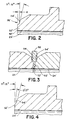
- Figs. 2 and 3 the preferred form for the annular sealing rib is shown in detail.
- the sealing face 26' has a circumferentially extending sealing rib 50' positioned closely adjacent the central passage 24'. As shown in Fig. 3, this assures that sealing takes place close to the bore line of passage 24'. This is desirable since it reduces fluid entrapment areas and provides a smooth flow area through the coupling.
- the annular sealing rib 50' has a substantially flat outer sealing surface 52' which is circumferentially and radially continuous and has a radial extent in the range of 0.38 to 0.89 mm (0.015 to 0.035 inch) in width. With this width, the force required to produce sealing penetration of the face into the associated gasket 30 is reduced by about 15% to 50% compared with most prior designs.
- the inner edge of the sealing surface 52' is preferably located on a diameter of 4.62mm (0.182 inch) and the outer periphery of the sealing surface 52' is located on a diameter of 5.77mm (0.227 inch) so that the band has a width of 0.58mm (0.023 inch).
- the sealing surface 52' is preferably in a plane which is perpendicular to the axis of the flow passage 24'. Alternatively, however, and as shown in Fig. 4, it is possible for this surface to be inclined from one degree up to as much as three degrees from the perpendicular.
- the innermost edge can extend axially outwardly beyond the remaining sealing surface and the sealing surface has the shape of a very shallow truncated cone.
- the surface finish R A of the sealing surfaces 52, 52' is preferably 25 to 125 micrometers (1 to 5 microinches).
- the opposed surfaces 52, 52' can be brought into direct engagement and no permanent deformation of the surfaces occurs up to the point that they have compressed into full engagement.
- these components can withstand many make-ups without damage to the seal surfaces.
- a second circumferentially continuous surface 54' which functions as a stop surface to limit penetration of the sealing surface into the associated gasket and to provide a rapid buildup in force to produce a distinct feel when proper sealing make-up has been achieved.
- This stop surface 54' is preferably inclined in the manner shown at an angle of 10 degrees but angles in the range of approximately 3 to 15 degrees from a plane perpendicular to the axis of passage 24' can be used.
- the distance d from the surface 52' to the start of surface 54' is in the range of 0.10 to 0.15 mm (0.004 to 0.006 inch) but a range 0.05 to 0.30mm (0.002 inch to 0.012 inch) appears to be satisfactory for most situations. This assures sufficient penetration to provide a proper seal.
Landscapes
- Engineering & Computer Science (AREA)
- General Engineering & Computer Science (AREA)
- Mechanical Engineering (AREA)
- Gasket Seals (AREA)
- Joints With Pressure Members (AREA)
Claims (9)
- Structure de liaison spécialement adaptée pour des dispositifs sous vide et du type comportant une paire de composants formant brides (12,14) adaptés pour avoir un mouvement relatif l'un vers l'autre le long d'un axe longitudinal (28) , chacun des composants formant bride ayant une face d'extrémité (26,26')perpendiculaire à l'axe longitudinal (28) , et un joint métallique (30) positionné perpendiculairement à l'axe longitudinal (28) entre les faces d'extrémité (26,26') des composants (12,14) formant bride, chacune des faces d'extrémité (26,26') ayant une saillie d'étanchéité (50,50') continue de manière circonférentielle pour mettre en contact le joint (30) avec les saillies (50,50') positionnées en étant alignées opposées par rapport aux côtés opposés du joint (30), chacune des faces d'extrémité (26,26') ayant aussi une surface (54,54') formant face de bride pour constituer une surface d'arrêt pour limiter la pénétration des saillies d'étanchéité (50,50') à l'intérieur dudit joint (30) , chacune desdites saillies d'étanchéité (50,50') étant située à une distance (d) axialement proche de la partie de la surface d'arrêt (54,54') respective qui est radialement la plus proche de la saillie d'étanchéité (50,50'),caractérisée en ce que le joint métallique (30) est plat et lisse avant compression et chacune desdites saillies (50, 50') comporte une bande d'étanchéité plate (52, 52') ayant une largeur radiale (W) pratiquement perpendiculaire audit axe (28), et en ce que chacune des surfaces d'arrêt (54, 54') est située radialement vers l'extérieur de sa bande d'étanchéité respective (52, 52') et est inclinée axialement en s'éloignant du joint sur un angle situé dans la plage allant approximativement de 3 à 15 degrés.
- Structure de liaison selon la revendication 1, dans laquelle lesdites bandes (52, 52') d'étanchéité continues sont inclinées par rapport à la perpendiculaire audit axe (28) au plus de trois degrés.
- Structure de liaison selon la revendication 1 ou 2, dans laquelle chaque bande (52, 52') d'étanchéité est reliée à sa surface (54, 54') d'arrêt associée par une surface de transition en arc de cercle.
- Structure de liaison selon l'une quelconque des revendications précédentes, dans laquelle ladite distance axiale (d) est d'au moins environ 0,05 mm (0,002 pouce)
- Structure de liaison selon l'une quelconque des revendications précédentes, dans laquelle ladite distance axiale (d) n'est pas plus grande de manière significative qu'environ 0,030 mm (0,012 pouce).
- Structure de liaison selon la revendication 5 comportant un écrou de raccord fileté pour déplacer les éléments à bride l'un vers l'autre.
- Structure de liaison selon l'une quelconque des revendications précédentes dans laquelle un passage d'écoulement (24, 24'), ayant une coupe transversale circulaire s'étend à travers chacune des faces d'extrémités (26, 26') et dans laquelle chaque bande d'étanchéité (52, 52') entoure étroitement le passage d'écoulement respectif (26, 26') dans la face d'extrémité associée.
- Structure le liaison selon la revendication 7, dans laquelle la bande d'étanchéité située sur chaque surface formant face de bride s'étend radialement vers l'extérieur sur une distance maximale adjacente au passage d'écoulement.
- Structure de liaison selon l'une quelconque des revendications précédentes, dans laquelle lesdites bandes d'étanchéité (52, 52') ont un fini de surface (RA) situé dans la plage de 25 à 125 micromètres (1 à 5 micro-pouces).
Applications Claiming Priority (2)
| Application Number | Priority Date | Filing Date | Title |
|---|---|---|---|
| US07/549,897 US5135269A (en) | 1990-07-09 | 1990-07-09 | Tube coupling |
| US549897 | 1990-07-09 |
Publications (3)
| Publication Number | Publication Date |
|---|---|
| EP0466371A2 EP0466371A2 (fr) | 1992-01-15 |
| EP0466371A3 EP0466371A3 (en) | 1992-02-26 |
| EP0466371B1 true EP0466371B1 (fr) | 1994-04-06 |
Family
ID=24194823
Family Applications (1)
| Application Number | Title | Priority Date | Filing Date |
|---|---|---|---|
| EP91305879A Expired - Lifetime EP0466371B1 (fr) | 1990-07-09 | 1991-06-28 | Raccord de tuyau |
Country Status (7)
| Country | Link |
|---|---|
| US (1) | US5135269A (fr) |
| EP (1) | EP0466371B1 (fr) |
| JP (1) | JPH05126285A (fr) |
| KR (1) | KR920002970A (fr) |
| CN (1) | CN1027833C (fr) |
| CA (1) | CA2046475A1 (fr) |
| DE (1) | DE69101596T2 (fr) |
Families Citing this family (28)
| Publication number | Priority date | Publication date | Assignee | Title |
|---|---|---|---|---|
| US5222747A (en) * | 1991-05-01 | 1993-06-29 | General Components, Inc. | Fitting with overtightening prevention gasket |
| US5505464A (en) * | 1989-08-11 | 1996-04-09 | General Components, Inc. | Minimum dead volume fitting |
| DE9011772U1 (de) * | 1990-08-13 | 1990-10-31 | Karl Rafeld KG Spritzgußwerk, Elektronik und Formenbau, 8954 Biessenhofen | Druckverschraubung für Heißwasser und aggressive Flüssigkeiten |
| US5251941A (en) * | 1991-10-11 | 1993-10-12 | General Components, Inc. | Fail safe fitting with first and second flange projections |
| US5196814A (en) * | 1991-11-01 | 1993-03-23 | The United States Of America As Represented By The United States Department Of Energy | High power, high frequency, vacuum flange |
| US5366261A (en) * | 1992-04-27 | 1994-11-22 | Fujikin Incorporated | Pipe joint with a gasket retainer |
| DE69427645T2 (de) * | 1993-10-06 | 2002-05-08 | Unit Instruments, Inc. | Apparat zur handhabung von prozess fluiden |
| US5490693A (en) | 1994-09-28 | 1996-02-13 | Cajon Company | Tube coupling locking device |
| US5782500A (en) * | 1995-05-26 | 1998-07-21 | Mate; Robert James | Passageway aligned coupling and process |
| US5681064A (en) * | 1995-07-07 | 1997-10-28 | Ewal Manufacturing Co., Inc. | Gasket retainer |
| US5673946A (en) * | 1995-07-07 | 1997-10-07 | Ewal Manufacturing Co., Inc. | Gasket assembly for a fluid coupling |
| US5855397A (en) * | 1997-04-02 | 1999-01-05 | Cummins Engine Company, Inc. | High-pressure sealable connector for a pressure sensor |
| CN1057978C (zh) * | 1997-04-10 | 2000-11-01 | 中国石油天然气总公司工程技术研究院 | 一种苦卤综合利用的方法 |
| US6623047B2 (en) * | 1997-06-16 | 2003-09-23 | Swagelok Company | Tube coupling |
| WO2003043892A1 (fr) * | 2001-11-19 | 2003-05-30 | Shin-Ei Kamishoko Co., Ltd. | Palette de manutention |
| JP2004043845A (ja) * | 2002-07-09 | 2004-02-12 | Nippon Steel Corp | 流体部品 |
| JP4058733B2 (ja) * | 2002-07-09 | 2008-03-12 | 新日鐵住金ステンレス株式会社 | 管継手 |
| JP2004043844A (ja) * | 2002-07-09 | 2004-02-12 | Nippon Steel Corp | 流体部品 |
| US6988748B2 (en) * | 2003-12-23 | 2006-01-24 | Martinrea Industries, Inc. | Fluid coupling assembly |
| US7207741B2 (en) * | 2004-09-30 | 2007-04-24 | Reliance Electric Technologies, Llc | Bushing system for power transmission products |
| KR100746494B1 (ko) * | 2005-11-08 | 2007-08-06 | 이도연 | 급수관에 스프링클러헤드를 간편하게 연결 할수 있는리듀싱 커플링 |
| US9772056B2 (en) * | 2009-03-05 | 2017-09-26 | Gates Corporation | Tube connector |
| JP5464171B2 (ja) * | 2011-05-25 | 2014-04-09 | 株式会社デンソー | 流体通路接続装置 |
| CN106322034A (zh) * | 2016-11-07 | 2017-01-11 | 中国工程物理研究院核物理与化学研究所 | 自锁式密封连接装置 |
| CN107042487A (zh) * | 2017-05-31 | 2017-08-15 | 浙江伟鑫金属制品有限公司 | 接头的扳手组件机构 |
| FR3079903B1 (fr) * | 2018-04-04 | 2022-12-23 | Commissariat Energie Atomique | Assemblage d'etancheite metallique pour l'etancheite entre un arbre tournant et un bati fixe |
| CN112268147A (zh) * | 2020-09-29 | 2021-01-26 | 中国原子能科学研究院 | 一种异种金属管道连接结构 |
| CN114776899B (zh) * | 2022-05-05 | 2024-06-28 | 浙江鲁溪密封件有限公司 | 机械密封装置 |
Citations (1)
| Publication number | Priority date | Publication date | Assignee | Title |
|---|---|---|---|---|
| US3521910A (en) * | 1968-11-12 | 1970-07-28 | Cajon Co | Tube coupling |
Family Cites Families (25)
| Publication number | Priority date | Publication date | Assignee | Title |
|---|---|---|---|---|
| FR1495732A (fr) * | 1967-12-20 | |||
| US401262A (en) * | 1889-04-09 | Renewable packing-ring | ||
| US1242568A (en) * | 1916-05-24 | 1917-10-09 | Clyde H Loughridge | Pipe-coupling. |
| US1715854A (en) * | 1923-03-06 | 1929-06-04 | Standard Dev Co | Fluid-tight joint |
| US1834581A (en) * | 1926-08-30 | 1931-12-01 | Safety Mining Co | Seal construction |
| US1825774A (en) * | 1927-11-21 | 1931-10-06 | Boynton Alexander | Casing head |
| US2528665A (en) * | 1946-06-17 | 1950-11-07 | Hannifin Corp | Gasket seal |
| US2926937A (en) * | 1955-07-05 | 1960-03-01 | Specialties Dev Corp | Fluid tight joint |
| US2937891A (en) * | 1957-11-04 | 1960-05-24 | Gressel Edmond | Reducing coupling |
| US3100656A (en) * | 1959-05-11 | 1963-08-13 | Hydril Co | Synthetic resin seal ring in tubing joint for plastic coated tubing |
| US3211478A (en) * | 1962-11-09 | 1965-10-12 | Thomas H Batzer | Aluminum foil ultra-high vacuum gasket seal |
| US3368818A (en) * | 1964-02-02 | 1968-02-13 | Nippon Electric Co | Vacuum flange |
| FR91871E (fr) * | 1966-03-24 | 1968-08-23 | Citroen Sa Andre | Raccord multiple pour canalisations de fluide |
| FR95486E (fr) * | 1967-03-30 | 1971-01-15 | Dev Des Ind Modernes S E D I M | Dispositif d'étanchéite a brides. |
| GB1521546A (en) * | 1974-11-26 | 1978-08-16 | Hoke Inc | Tubular couplings |
| US3989285A (en) * | 1974-12-23 | 1976-11-02 | The United States Of America As Represented By The Secretary Of The Army | Compatible vacuum seal |
| NL188244C (nl) * | 1978-12-04 | 1992-05-06 | Varian Associates | Demonteerbare metalen flenspakking. |
| US4650227B1 (en) * | 1982-08-23 | 2000-11-28 | Cajon Co | Fluid coupling |
| US4616860A (en) * | 1984-03-12 | 1986-10-14 | Thermionics Laboratory, Inc. | Seal structure for metal vacuum joint |
| US4705307A (en) * | 1984-09-21 | 1987-11-10 | James B. N. Morris | Tubular goods joint |
| USH439H (en) * | 1986-06-02 | 1988-03-01 | The United States Of America As Represented By The Secretary Of The Navy | Ultrahigh vacuum mounting |
| US4854597A (en) * | 1988-01-22 | 1989-08-08 | General Components, Inc. | Metal gasket having conical and radial sealing surfaces and method of using the gasket with a tubular element |
| JP2656102B2 (ja) * | 1987-10-09 | 1997-09-24 | エフェレル エス.アー. | 2つの筒状素子を端面にて密接結合せしめる交換自在環状金属結合継手及びこれに用いる万能シール |
| FR2647872B1 (fr) * | 1989-05-31 | 1991-09-06 | Leduc Rene Hydro Sa | Joint hydraulique tournant a equilibrage hydrostatique |
| US5066051A (en) * | 1990-01-23 | 1991-11-19 | Cajon Company | Anti-twist coupling assembly with biasing means |
-
1990
- 1990-07-09 US US07/549,897 patent/US5135269A/en not_active Expired - Fee Related
-
1991
- 1991-06-28 DE DE69101596T patent/DE69101596T2/de not_active Expired - Fee Related
- 1991-06-28 EP EP91305879A patent/EP0466371B1/fr not_active Expired - Lifetime
- 1991-07-05 JP JP3165376A patent/JPH05126285A/ja active Pending
- 1991-07-08 CA CA002046475A patent/CA2046475A1/fr not_active Abandoned
- 1991-07-09 CN CN91104445A patent/CN1027833C/zh not_active Expired - Fee Related
- 1991-07-09 KR KR1019910011595A patent/KR920002970A/ko not_active Ceased
Patent Citations (1)
| Publication number | Priority date | Publication date | Assignee | Title |
|---|---|---|---|---|
| US3521910A (en) * | 1968-11-12 | 1970-07-28 | Cajon Co | Tube coupling |
Also Published As
| Publication number | Publication date |
|---|---|
| CA2046475A1 (fr) | 1992-01-10 |
| JPH05126285A (ja) | 1993-05-21 |
| CN1058462A (zh) | 1992-02-05 |
| US5135269A (en) | 1992-08-04 |
| EP0466371A3 (en) | 1992-02-26 |
| KR920002970A (ko) | 1992-02-28 |
| DE69101596T2 (de) | 1994-07-21 |
| CN1027833C (zh) | 1995-03-08 |
| DE69101596D1 (de) | 1994-05-11 |
| EP0466371A2 (fr) | 1992-01-15 |
Similar Documents
| Publication | Publication Date | Title |
|---|---|---|
| US5135269A (en) | Tube coupling | |
| US5947533A (en) | Gasket assembly with elastomer expansion area | |
| US5145219A (en) | Tube coupling with gasket retainer | |
| US4779901A (en) | Sealed rigid pipe joint | |
| EP0439328B1 (fr) | Raccord de tuyaux | |
| AU693025B2 (en) | Coupling assembly | |
| AU640146B2 (en) | Gasket for Leaktight Locked Joints | |
| EP1481184B1 (fr) | Raccord de tuyauterie | |
| EP0757768B1 (fr) | Dispositif de raccordement permanent de tubes | |
| US6843514B2 (en) | Pipe coupling device | |
| US4119335A (en) | Pipe and tubing connectors | |
| US4732416A (en) | Pipe connectors | |
| KR100341298B1 (ko) | 파이프겹치기이음용커플링및이커플링제조용펀치와다이세트 | |
| US4648632A (en) | High pressure flow line connection | |
| US5649713A (en) | Gasket for hub and spigot pipe joints | |
| US4186947A (en) | Radial compression gasket | |
| US5505464A (en) | Minimum dead volume fitting | |
| EP0309179A1 (fr) | Raccord vissé | |
| US20120074694A1 (en) | Self-aligning sanitary pipe joints and related systems | |
| US5058935A (en) | Fluid fitting with torque suppression arrangement | |
| CA1285301C (fr) | Dispositif de raccordement etanche bout-a-bout de deux tuyaux | |
| CA2106120A1 (fr) | Assemblage de joints de tuyaux | |
| CA2136772A1 (fr) | Raccord pour tuyauterie | |
| US3924881A (en) | Injection molded plastic pipe fitting | |
| US4452474A (en) | High pressure flow line connection |
Legal Events
| Date | Code | Title | Description |
|---|---|---|---|
| PUAI | Public reference made under article 153(3) epc to a published international application that has entered the european phase |
Free format text: ORIGINAL CODE: 0009012 |
|
| PUAL | Search report despatched |
Free format text: ORIGINAL CODE: 0009013 |
|
| AK | Designated contracting states |
Kind code of ref document: A2 Designated state(s): BE CH DE FR GB IT LI NL |
|
| AK | Designated contracting states |
Kind code of ref document: A3 Designated state(s): BE CH DE FR GB IT LI NL |
|
| RHK1 | Main classification (correction) |
Ipc: F16L 19/02 |
|
| 17P | Request for examination filed |
Effective date: 19920519 |
|
| 17Q | First examination report despatched |
Effective date: 19920819 |
|
| GRAA | (expected) grant |
Free format text: ORIGINAL CODE: 0009210 |
|
| AK | Designated contracting states |
Kind code of ref document: B1 Designated state(s): BE CH DE FR GB IT LI NL |
|
| ET | Fr: translation filed | ||
| REF | Corresponds to: |
Ref document number: 69101596 Country of ref document: DE Date of ref document: 19940511 |
|
| ITF | It: translation for a ep patent filed | ||
| PLBE | No opposition filed within time limit |
Free format text: ORIGINAL CODE: 0009261 |
|
| STAA | Information on the status of an ep patent application or granted ep patent |
Free format text: STATUS: NO OPPOSITION FILED WITHIN TIME LIMIT |
|
| 26N | No opposition filed | ||
| PGFP | Annual fee paid to national office [announced via postgrant information from national office to epo] |
Ref country code: NL Payment date: 19970331 Year of fee payment: 7 |
|
| PGFP | Annual fee paid to national office [announced via postgrant information from national office to epo] |
Ref country code: CH Payment date: 19970630 Year of fee payment: 7 |
|
| PGFP | Annual fee paid to national office [announced via postgrant information from national office to epo] |
Ref country code: BE Payment date: 19970708 Year of fee payment: 7 |
|
| PG25 | Lapsed in a contracting state [announced via postgrant information from national office to epo] |
Ref country code: LI Free format text: LAPSE BECAUSE OF NON-PAYMENT OF DUE FEES Effective date: 19980630 Ref country code: CH Free format text: LAPSE BECAUSE OF NON-PAYMENT OF DUE FEES Effective date: 19980630 Ref country code: BE Free format text: LAPSE BECAUSE OF NON-PAYMENT OF DUE FEES Effective date: 19980630 |
|
| PGFP | Annual fee paid to national office [announced via postgrant information from national office to epo] |
Ref country code: GB Payment date: 19980702 Year of fee payment: 8 |
|
| PGFP | Annual fee paid to national office [announced via postgrant information from national office to epo] |
Ref country code: FR Payment date: 19980707 Year of fee payment: 8 |
|
| PGFP | Annual fee paid to national office [announced via postgrant information from national office to epo] |
Ref country code: DE Payment date: 19980728 Year of fee payment: 8 |
|
| BERE | Be: lapsed |
Owner name: CAJON CY Effective date: 19980630 |
|
| PG25 | Lapsed in a contracting state [announced via postgrant information from national office to epo] |
Ref country code: NL Free format text: LAPSE BECAUSE OF NON-PAYMENT OF DUE FEES Effective date: 19990101 |
|
| REG | Reference to a national code |
Ref country code: CH Ref legal event code: PL |
|
| NLV4 | Nl: lapsed or anulled due to non-payment of the annual fee |
Effective date: 19990101 |
|
| PG25 | Lapsed in a contracting state [announced via postgrant information from national office to epo] |
Ref country code: GB Free format text: LAPSE BECAUSE OF NON-PAYMENT OF DUE FEES Effective date: 19990628 |
|
| PG25 | Lapsed in a contracting state [announced via postgrant information from national office to epo] |
Ref country code: FR Free format text: THE PATENT HAS BEEN ANNULLED BY A DECISION OF A NATIONAL AUTHORITY Effective date: 19990630 |
|
| GBPC | Gb: european patent ceased through non-payment of renewal fee |
Effective date: 19990628 |
|
| PG25 | Lapsed in a contracting state [announced via postgrant information from national office to epo] |
Ref country code: DE Free format text: LAPSE BECAUSE OF NON-PAYMENT OF DUE FEES Effective date: 20000503 |
|
| REG | Reference to a national code |
Ref country code: FR Ref legal event code: ST |
|
| PG25 | Lapsed in a contracting state [announced via postgrant information from national office to epo] |
Ref country code: IT Free format text: LAPSE BECAUSE OF NON-PAYMENT OF DUE FEES Effective date: 20050628 |