EP0466455A2 - Appareil de ventilation - Google Patents
Appareil de ventilation Download PDFInfo
- Publication number
- EP0466455A2 EP0466455A2 EP91306217A EP91306217A EP0466455A2 EP 0466455 A2 EP0466455 A2 EP 0466455A2 EP 91306217 A EP91306217 A EP 91306217A EP 91306217 A EP91306217 A EP 91306217A EP 0466455 A2 EP0466455 A2 EP 0466455A2
- Authority
- EP
- European Patent Office
- Prior art keywords
- air
- duct
- plenum chamber
- diffuser
- sensor
- Prior art date
- Legal status (The legal status is an assumption and is not a legal conclusion. Google has not performed a legal analysis and makes no representation as to the accuracy of the status listed.)
- Withdrawn
Links
- 238000009423 ventilation Methods 0.000 title claims abstract description 14
- 238000011144 upstream manufacturing Methods 0.000 claims abstract description 7
- 230000000694 effects Effects 0.000 claims description 4
- 238000010438 heat treatment Methods 0.000 description 6
- XLYOFNOQVPJJNP-UHFFFAOYSA-N water Substances O XLYOFNOQVPJJNP-UHFFFAOYSA-N 0.000 description 5
- 238000001514 detection method Methods 0.000 description 2
- 238000010586 diagram Methods 0.000 description 2
- 238000005259 measurement Methods 0.000 description 2
- 238000005057 refrigeration Methods 0.000 description 2
- VYPSYNLAJGMNEJ-UHFFFAOYSA-N Silicium dioxide Chemical compound O=[Si]=O VYPSYNLAJGMNEJ-UHFFFAOYSA-N 0.000 description 1
- 238000004378 air conditioning Methods 0.000 description 1
- 230000001143 conditioned effect Effects 0.000 description 1
- 238000001816 cooling Methods 0.000 description 1
- 238000006073 displacement reaction Methods 0.000 description 1
- 230000009429 distress Effects 0.000 description 1
- 238000009434 installation Methods 0.000 description 1
- 239000000463 material Substances 0.000 description 1
- 239000000741 silica gel Substances 0.000 description 1
- 229910002027 silica gel Inorganic materials 0.000 description 1
- 239000007787 solid Substances 0.000 description 1
- 238000005507 spraying Methods 0.000 description 1
Images


Classifications
-
- F—MECHANICAL ENGINEERING; LIGHTING; HEATING; WEAPONS; BLASTING
- F24—HEATING; RANGES; VENTILATING
- F24F—AIR-CONDITIONING; AIR-HUMIDIFICATION; VENTILATION; USE OF AIR CURRENTS FOR SCREENING
- F24F3/00—Air-conditioning systems in which conditioned primary air is supplied from one or more central stations to distributing units in the rooms or spaces where it may receive secondary treatment; Apparatus specially designed for such systems
- F24F3/044—Systems in which all treatment is given in the central station, i.e. all-air systems
- F24F3/048—Systems in which all treatment is given in the central station, i.e. all-air systems with temperature control at constant rate of air-flow
- F24F3/052—Multiple duct systems, e.g. systems in which hot and cold air are supplied by separate circuits from the central station to mixing chambers in the spaces to be conditioned
-
- F—MECHANICAL ENGINEERING; LIGHTING; HEATING; WEAPONS; BLASTING
- F24—HEATING; RANGES; VENTILATING
- F24F—AIR-CONDITIONING; AIR-HUMIDIFICATION; VENTILATION; USE OF AIR CURRENTS FOR SCREENING
- F24F11/00—Control or safety arrangements
- F24F11/70—Control systems characterised by their outputs; Constructional details thereof
- F24F11/72—Control systems characterised by their outputs; Constructional details thereof for controlling the supply of treated air, e.g. its pressure
- F24F11/74—Control systems characterised by their outputs; Constructional details thereof for controlling the supply of treated air, e.g. its pressure for controlling air flow rate or air velocity
Definitions
- This invention relates to ventilation apparatus, and in particular to ventilation apparatus adapted to the regulation of air temperatures in rooms or other spaces served by the apparatus.
- air which has been cooled or heated by passing through a central refrigeration or heating installation is circulated by ducts, usually located in a space above the ceilings of the respective spaces.
- the air is then fed to diffusers which are supplied by branches from the duct, into the respective spaces.
- An object of the present invention is to provide ventilation apparatus which can overcome the aforementioned disadvantages of known apparatus.
- ventilation apparatus comprising at least one duct for supplying air to at least one diffuser wherein a plenum chamber is provided between the diffuser and the duct and a variable constriction valve is provided for controlling air flow to the diffuser, characterised in that the valve is provided between the duct and the plenum chamber.
- this preferably has a greater cross-sectional area than said duct or said diffuser.
- the valve has an inlet containing a constriction member having a first surface which faces towards the duct and a connecting second surface which faces towards the diffuser in the normal direction of air flow, the member being pivotable to adjust the angle of the first surface to the air flow and hence the constriction of the inlet.
- the first surface of the constriction member is provided by a substantially flat flap which is pivotally mounted at one end, and the second surface is provided by an extension part at the opposite end of the flap which is curved convexly away therefrom.
- the inlet may be elongate and the constriction member may be mounted on an axis which is driven by a motor, extending longitudinally of the longest dimension of the inlet, which is preferably parallel to the axis of the duct.
- the surfaces of the constriction member may be presented by a solid body, but preferably are of a suitable sheet material.
- An automatic control system is preferably provided to effect automatic operation of the valve in response to a sensed parameter.
- the aforesaid motor operating the constriction member is preferably controlled e.g. by a micro-processor based control system, which obtains data concerning ambient temperatures and flow rates of air to the respective diffuser, and effects variations to achieve or maintain a predetermined temperature.
- a pressure sensor may be provided to provide the aforesaid sensed parameter, said sensor being arranged to sense pressure between the duct and the plenum chamber.
- This sensor may be arranged to monitor the pressure averaged over a length and, in a particularly preferred embodiment the sensor comprises a pair of parallel tubes an upstream one of said tubes having a plurality of holes facing towards the air flow, and the downstream one of said tubes having a plurality of holes facing away from the air flow, and a respective pressure measuring device being applied to each said tube.
- a hot wire air velocity sensor may be used.
- thermosensor it is also possible to use a temperature sensor to provide said sensed parameter, said sensor being arranged to sense ambient temperature.
- a temperature adjusting device may be provided within the plenum chamber for supplying heat to or for removing heat from air in the plenum chamber.
- one said diffuser is arranged to be supplied with air from two said ducts via a common said plenum chamber and via respective said variable constriction valves, said ducts being arranged to supply air at different respective temperatures.
- Fig. 1 shows a duct 10 for the distribution of, for example, cooled air to rooms or other spaces in an air conditioned building.
- This duct may be housed in a ceiling space, and is connected to a plurality of diffusers such as 11, located at spaced apart intervals along the duct 10, for example, one, two or more in each room, depending on the size of the room.
- the air intake from the duct 10 for each diffuser 11 is in the form of an elongate rectangular housing 12, opening into the duct at one side, and into a plenum chamber 13, parallel to the duct 10 and equal in length to the diffuser 11, which plenum chamber 13 is of substantially greater cross-sectional area than the intake housing 12.
- the intake 12 as shown in Fig. 2 contains a valve or variable constrictor means 14, which includes a movable element 15 and a shaft 16 which is driven by a pneumatic or electric actuator which may be a stepping motor or an analogue (continuously variable) equivalent, under the control of a controller (to be described below).
- the shaft 16 causes rotational displacement of the element 15, which has a rectilinear or flat face 17 directed towards the direction of flow of air into the housing 12 from duct 10, and a curved trailing face 18, the free edge of which slidingly abuts a wall 19 to prevent inflow of air into a space 20 provided to accommodate the movable element 15.
- the trailing face 18 prevents turbulent flow of air into the space behind the face 17 of the element 15, thereby reducing noise, and encourages laminar flow of air past the element 15, with enhanced intake efficiency as well as reduced noise.
- the element 15 can be moved between positions respectively fully opening and fully closing the passage through the intake housing 12.
- air from the duct 10 After passing through housing 12, and the variable constriction valve 14, air from the duct 10 enters the plenum chamber 13.
- the air is fed from the chamber 13 through the diffuser 11, which is of known type, and includes for example filters 21.
- the air from the duct 10 may be mixed with air of different temperatures from other sources, or subject to direct heating by e.g. a heating element 22.
- Heating element 22 can be for example a coil for circulating heated water through the plenum chamber 13, or an electrical heating element.
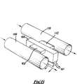
- An air flow pressure measuring device 25 is located close to the inlet of the housing 12 from duct 10, the position being indicated in Fig. 2.
- the device 25 itself can be either a hot wire anemometer type or differential pressure type, and the latter is shown in more detail in Fig. 3 and comprises two parallel tubes, 26, 27 extending lengthwise across the longest dimension (orthogonal to the air intake flow) of the housing 12.
- the upstream tube 26 is provided with a series of holes 28 spaced at e.g. 50mm centres directed towards the flow of air into the housing, and the downstream tube 27 is provided similarly with a series of holes 29, similarly spaced at 50mm centres, directed away from the flow of air.
- the tubes 26, 27 are connected to pressure sensing transducers which detect and sense and convert into the measurement signals the air pressures appearing in the respective tubes 26, 27 and monitor the differential between them, which is in turn related to the velocity of air flow into the housing 12.
- the holes 28 in tube 26 being directed upstream, admit air to tube 26 at a higher pressure
- holes 29 in tube 27, being directed downstream, into the lee side of the tubes, admits air to tube 27 at a lower pressure. The greater the air flow speed, the greater will be the differential between these pressures.
- Fig. 4 illustrates the fact that all the diffusers 11 serving a given space or room require to be individually controlled; if as shown in Fig. 4 an office room 30, has three diffusers 11a, 11b, 11c, each with respective plenum chambers 13a, 13b, 13c, and with air flow in duct 10 from left to right (arrow A) in the drawing, then there will normally be a pressure drop in the intake from the duct 10 of the respective diffusers from left to right. This may be compensated for in controlling the setting of the valves 14 to achieve equal flow rates into the respective plenum chambers and thus the diffusers.
- FIG. 5 illustrates by way of a diagram, the operation of ventilating apparatus of the invention using a differential pressure air flow measuring device.
- a temperature detector 40 measures the external or internal temperature, e.g. the actual temperature from moment to moment of an office room such as 30.
- Pressure detectors 41 connected to the tubes 26, 27 in the respective housings 12 leading to each diffuser 11 also monitor, with reference to the respective difference in pressure between each pair of tubes 26, 27, the air flow rate from moment to moment into each housing 12.
- This data is applied to a control unit 42, which may be a microprocessor or functionally equivalent device, and compared with preprogrammed instructions to determine what variations in airflow to effect in order to achieve or maintain a desired air temperature.
- each movable element 15 of each valve 14 is rotated by its respective motor according to instructions from the control unit 42, thereby varying the volume of air flow through each housing 12 into the respective plenum chamber 13.
- the air supplied via duct 10 will be air which has been cooled by passing through a refrigeration plant, however in cold climates or in winter this may be replaced by a pre-heated airflow.
- a supply of air of the opposite type i.e. heated air when the ducted air is cooled or cooled air when the ducted air is heated
- a water circulating coil e.g. 22, in the plenum chamber. This may circulate heated water; or chilled water as required.
- Such an arrangement can be used to compensate for unseasonably mild winter weather on one hand, or late/early frosts in summer, and the passage of warm and cold fronts.
- Humidity may also be allowed for, e.g. by spraying water into the plenum chamber 13 when air is excessively dry, or use of a by pass through a desiccator such as silica gel, when the humidity is excessive.
- a desiccator such as silica gel
- a feature of the invention is the ability to connect the apparatus to separate prewarmed and chilled air supplies and for the supply volume of air passing through the diffuser to be mixed and controlled in the plenum chamber.
- Such an arrangement is shown in Fig. 6, wherein two parallel air supply ducts 100, 110 are provided, duct 100 supplying heated air, and duct 110 supplying chilled air.
- Each duct is connected via a respective housing 102, 112, to a single plenum chamber 103 wherein the flows from the ducts 100, 110 are mixed, to produce an outflow of air of a desired temperature from diffuser 101.
- the flow proportions of warmed and chilled air are controlled in the housing 102, 112 by respective flap valves each as shown in Fig. 2 and as described in relation thereto, and each independently operable under command of a control unit such as C.P.U. 40 in Fig. 5 to produce the desired temperature and total flow of mixed air.
Landscapes
- Engineering & Computer Science (AREA)
- Chemical & Material Sciences (AREA)
- Combustion & Propulsion (AREA)
- Mechanical Engineering (AREA)
- General Engineering & Computer Science (AREA)
- Physics & Mathematics (AREA)
- Fluid Mechanics (AREA)
- Duct Arrangements (AREA)
- Air-Flow Control Members (AREA)
- Air Conditioning Control Device (AREA)
Applications Claiming Priority (2)
| Application Number | Priority Date | Filing Date | Title |
|---|---|---|---|
| GB909015378A GB9015378D0 (en) | 1990-07-12 | 1990-07-12 | Ventilation apparatus |
| GB9015378 | 1990-07-12 |
Publications (2)
| Publication Number | Publication Date |
|---|---|
| EP0466455A2 true EP0466455A2 (fr) | 1992-01-15 |
| EP0466455A3 EP0466455A3 (en) | 1992-11-19 |
Family
ID=10679011
Family Applications (1)
| Application Number | Title | Priority Date | Filing Date |
|---|---|---|---|
| EP19910306217 Withdrawn EP0466455A3 (en) | 1990-07-12 | 1991-07-09 | Ventilation apparatus |
Country Status (2)
| Country | Link |
|---|---|
| EP (1) | EP0466455A3 (fr) |
| GB (2) | GB9015378D0 (fr) |
Cited By (2)
| Publication number | Priority date | Publication date | Assignee | Title |
|---|---|---|---|---|
| WO1997021963A1 (fr) * | 1995-12-08 | 1997-06-19 | Air Innovation Sweden Ab | Boitier melangeur destine a melanger des courants d'air de temperatures differentes en provenance de deux canaux tubulaires |
| EP1553359A1 (fr) | 2004-01-12 | 2005-07-13 | Schako Klima Luft Ferdinand Schad KG | Dispositif de guidage d'un flux d'air |
Family Cites Families (10)
| Publication number | Priority date | Publication date | Assignee | Title |
|---|---|---|---|---|
| US3026041A (en) * | 1960-05-06 | 1962-03-20 | Robertson Co H H | Conditioned air distribution |
| US3974859A (en) * | 1974-08-19 | 1976-08-17 | The Trane Company | Air distribution regulator apparatus |
| US3937398A (en) * | 1974-09-06 | 1976-02-10 | Dynamics Corporation Of America | Conditioned air distribution system |
| US4077567A (en) * | 1976-06-18 | 1978-03-07 | Universal Pneumatic Controls, Inc. | Pneumatic temperature reset differential pressure controller |
| DE2653161C2 (de) * | 1976-11-23 | 1981-09-24 | Schako Verwaltung Beck KG, 7790 Meßkirch | Luftverteilkasten für Belüftungs- und Klimaanlagen |
| US4186876A (en) * | 1977-12-07 | 1980-02-05 | Carrier Corporation | System powered damper blade assembly for use in an air conditioning system |
| DE8432304U1 (de) * | 1984-11-05 | 1985-04-18 | Gebrüder Trox, GmbH, 4133 Neukirchen-Vluyn | Druckmessvorrichtung fuer eine klimatechnischen anlage |
| US4637546A (en) * | 1985-09-16 | 1987-01-20 | Johnson Service Company | Pneumatic differential pressure controller |
| FI82307C (sv) * | 1987-09-23 | 1991-02-11 | Palander Carl Gustav | Ventilationsanordning |
| GB9004639D0 (en) * | 1990-03-01 | 1990-04-25 | Actionair Equip | Improvements in air diffusers and/or plenum boxes |
-
1990
- 1990-07-12 GB GB909015378A patent/GB9015378D0/en active Pending
-
1991
- 1991-07-09 GB GB9114737A patent/GB2248105B/en not_active Expired - Fee Related
- 1991-07-09 EP EP19910306217 patent/EP0466455A3/en not_active Withdrawn
Cited By (3)
| Publication number | Priority date | Publication date | Assignee | Title |
|---|---|---|---|---|
| WO1997021963A1 (fr) * | 1995-12-08 | 1997-06-19 | Air Innovation Sweden Ab | Boitier melangeur destine a melanger des courants d'air de temperatures differentes en provenance de deux canaux tubulaires |
| US6102792A (en) * | 1995-12-08 | 2000-08-15 | Air Innovation Sweden Ab | Mixing box for mixing air streams from two tubular channels |
| EP1553359A1 (fr) | 2004-01-12 | 2005-07-13 | Schako Klima Luft Ferdinand Schad KG | Dispositif de guidage d'un flux d'air |
Also Published As
| Publication number | Publication date |
|---|---|
| GB2248105A (en) | 1992-03-25 |
| GB2248105B (en) | 1994-05-25 |
| GB9114737D0 (en) | 1991-08-28 |
| EP0466455A3 (en) | 1992-11-19 |
| GB9015378D0 (en) | 1990-08-29 |
Similar Documents
| Publication | Publication Date | Title |
|---|---|---|
| US5249596A (en) | Residential heating and air conditioning barometric bypass damper | |
| US3951205A (en) | Air-conditioning apparatus | |
| US4872397A (en) | Personal environmental module | |
| EP0097607B1 (fr) | Appareil de chauffage à débit d'air variable pour différentes zones chauffées | |
| US4531454A (en) | Air conditioning system | |
| US20050028970A1 (en) | Dual-compartmet ventilation and air-conditioning system having a shared heating coil | |
| US20030085033A1 (en) | Double duct changeover HVAC system | |
| SE9504564L (sv) | Klimatanläggning och förfarande för reglering av klimatanläggning | |
| KR840000064B1 (ko) | 공기 조화장치 | |
| US5318099A (en) | Method and apparatus for emulating a perimeter induction unit air conditioning system | |
| US5080282A (en) | Air conditioning apparatus | |
| US2739792A (en) | Air conditioning systems using heat exchangers local to the conditioned space | |
| JPH05118614A (ja) | 空気調和機 | |
| KR101578124B1 (ko) | 다수의 객실 온도를 탄력적으로 조절하기 위한 2-채널 에어컨 | |
| JP3013964B2 (ja) | アンダーフロア空調システム | |
| GB2248105A (en) | Ventilation apparatus | |
| JPH05312387A (ja) | 空気調和システム | |
| US4102494A (en) | Air distribution system | |
| JP3040296B2 (ja) | 空調用吹出し装置 | |
| JPH09184645A (ja) | 多数室可変風量換気装置 | |
| JPH07260201A (ja) | アンダーフロア空調システム | |
| JPH10132307A (ja) | ダクトレス空調システム | |
| JPH0544965A (ja) | 輻射熱利用の冷暖房設備 | |
| US2984082A (en) | Air conditioning system | |
| FI110280B (fi) | Ilmastointimenetelmä ja ilmastointijärjestelmä |
Legal Events
| Date | Code | Title | Description |
|---|---|---|---|
| PUAI | Public reference made under article 153(3) epc to a published international application that has entered the european phase |
Free format text: ORIGINAL CODE: 0009012 |
|
| AK | Designated contracting states |
Kind code of ref document: A2 Designated state(s): AT BE CH DE DK ES FR GB GR IT LI LU NL SE |
|
| PUAL | Search report despatched |
Free format text: ORIGINAL CODE: 0009013 |
|
| AK | Designated contracting states |
Kind code of ref document: A3 Designated state(s): AT BE CH DE DK ES FR GB GR IT LI LU NL SE |
|
| STAA | Information on the status of an ep patent application or granted ep patent |
Free format text: STATUS: THE APPLICATION IS DEEMED TO BE WITHDRAWN |
|
| 18D | Application deemed to be withdrawn |
Effective date: 19930520 |