EP0466461A2 - Verfahren und Gerät zur Montage eines zusammengesetzten Bildes anhand verschiedener Datentypen - Google Patents
Verfahren und Gerät zur Montage eines zusammengesetzten Bildes anhand verschiedener Datentypen Download PDFInfo
- Publication number
- EP0466461A2 EP0466461A2 EP91306225A EP91306225A EP0466461A2 EP 0466461 A2 EP0466461 A2 EP 0466461A2 EP 91306225 A EP91306225 A EP 91306225A EP 91306225 A EP91306225 A EP 91306225A EP 0466461 A2 EP0466461 A2 EP 0466461A2
- Authority
- EP
- European Patent Office
- Prior art keywords
- data
- image data
- image
- files
- real time
- Prior art date
- Legal status (The legal status is an assumption and is not a legal conclusion. Google has not performed a legal analysis and makes no representation as to the accuracy of the status listed.)
- Withdrawn
Links
Images


Classifications
-
- G—PHYSICS
- G06—COMPUTING OR CALCULATING; COUNTING
- G06K—GRAPHICAL DATA READING; PRESENTATION OF DATA; RECORD CARRIERS; HANDLING RECORD CARRIERS
- G06K15/00—Arrangements for producing a permanent visual presentation of the output data, e.g. computer output printers
- G06K15/02—Arrangements for producing a permanent visual presentation of the output data, e.g. computer output printers using printers
- G06K15/12—Arrangements for producing a permanent visual presentation of the output data, e.g. computer output printers using printers by photographic printing, e.g. by laser printers
- G06K15/1276—Arrangements for producing a permanent visual presentation of the output data, e.g. computer output printers using printers by photographic printing, e.g. by laser printers adding two or more images, e.g. texturing, shading, form overlay
-
- G—PHYSICS
- G06—COMPUTING OR CALCULATING; COUNTING
- G06K—GRAPHICAL DATA READING; PRESENTATION OF DATA; RECORD CARRIERS; HANDLING RECORD CARRIERS
- G06K15/00—Arrangements for producing a permanent visual presentation of the output data, e.g. computer output printers
- G06K15/02—Arrangements for producing a permanent visual presentation of the output data, e.g. computer output printers using printers
- G06K15/12—Arrangements for producing a permanent visual presentation of the output data, e.g. computer output printers using printers by photographic printing, e.g. by laser printers
- G06K15/129—Colour printing
-
- H—ELECTRICITY
- H04—ELECTRIC COMMUNICATION TECHNIQUE
- H04N—PICTORIAL COMMUNICATION, e.g. TELEVISION
- H04N1/00—Scanning, transmission or reproduction of documents or the like, e.g. facsimile transmission; Details thereof
- H04N1/387—Composing, repositioning or otherwise geometrically modifying originals
- H04N1/3871—Composing, repositioning or otherwise geometrically modifying originals the composed originals being of different kinds, e.g. low- and high-resolution originals
-
- H—ELECTRICITY
- H04—ELECTRIC COMMUNICATION TECHNIQUE
- H04N—PICTORIAL COMMUNICATION, e.g. TELEVISION
- H04N1/00—Scanning, transmission or reproduction of documents or the like, e.g. facsimile transmission; Details thereof
- H04N1/46—Colour picture communication systems
Definitions
- the present invention relates generally to high resolution graphic production, and more specifically, relates to real time data processing of multiple image data to produce a composite.
- layout information generated by some form of digital input.
- This input may be generated by a digital scanner or electronic work station which is used to create a montage.
- the layout information may have a variety of formats and protocols.
- the conversion process is typically preceded by a lengthy pre-processing step called a final page run, in which the three data types are converted into a common data format and the multiple images of the same data type are merged into one single file. Even though the resulting data stream defines a high-quality, high-resolution, four color separated image, the final page run unfortunately takes about an hour to complete.
- the commercially available Hell Chromacom 1000 system coupled to a DC 350 output recorder operates in this fashion.
- U.S. Patent No. 4,729,037, Doelves is concerned with the production of printed material using image input from multiple sources.
- the system is designed for production of catalogs using high resolution data to be received from a scanner and relatively lower resolution data from a digital memory. To function in near real time, the system requires the data to be presented from the data sources synchronously.
- the Sing system is further limited in the types of data which can be processed automatically without operator supervision.
- High resolution compressed data for example, must be expanded under direct operator control before it can be intermixed with other data types.
- High resolution contour data involving a color change within a pixel must be similarly processed by the operator before being combined.
- U.S. Patent No. 4,419,690, Hammes shows a system which has a limited capacity to process input data of varying resolutions.
- a more flexible system is shown in U.S. Patent No. 4,647,962, Rosen, et al. Though the system of Rosen, et al. provides for a greater range in the resolution of the input data, combining multiple images in the same proof is not provided without direct operator supervision.
- the present invention overcomes the problems associated with the prior art systems by providing a technique for combining image, geometric, and textual data of differing formats and resolutions into a single composite proof.
- the combining process occurs in real time.
- the image data files are received by a host interface in a variety of formats and placed on a standard bus from which they are transferred into system memory. Each data file is reformatted into one or more files and transferred to a data storage system under the control of a central processing unit. These transfer, reformatting, and storage procedures occur in parallel in real time at a data rate limited by the maximum data rate of the host system or by the data storage system, whichever is slower.
- the data is retrieved in accordance with a prepared map for transmission on the data bus to special purpose real time hardware conversion modules.
- the map is prepared in such a way as to optimize the speed of retrieving multiple image data files in parallel from the data storage system.
- the hardware conversion modules then convert the various data formats to halftone pixel data in real time for output to the recording device at data rates limited by the data storage device or by the recording device, whichever is slower.
- low resolution files may be prepared in parallel during the reformatting process for preview by the operator at the video terminal of a work station. These low resolution files may be held in a database for convenient retrieval of archived images at a later date.
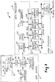
- FIG. 1 is an overall block diagram of an image system 10 employing the present invention.
- the primary source of the image data is data source 12, which is shown in representative form.
- data source 12 includes scanner drum 22, which rotates about axle 24 in the direction of arrow 26 to completely expose viewing area 30 of sensor 28 around the entire radius of an image placed on scanner drum 22. Complete longitudinal access is provided by movement of sensor 28 in the direction of arrow 32.
- the output of sensor 28 is digitized by analog-to-digital converter 34 and buffered in host data base 36.
- other scanner devices may be included in data source 12 depending upon specific requirements.
- data source 12 other image generators for data source 12 include Line Art/Text generator 38 and contour generator 40.
- contour generator 40 The exact configuration of data source 12 may vary, and is not intended to limit the present invention. It may be constructed from components which are well known in the art.
- Data from data source 12 is coupled to data processor 14 by cable 42.
- the data is coupled to the internal VME bus 58 of data processor 14 by host bus interface 50. It is important that host interface 50 be provided with direct memory access (DMA) capability so that excess CPU time is not consumed during high speed transfers of large blocks of data.
- DMA direct memory access
- the internal VME bus 58 hardware is readily available from MuPak, Inc. of Boston, Mass. Internal VME bus 58 provides the major data and control interface to the components within data processor 14 and to the major components of video processor 16.
- disk drive 52 The largest facility for storing image data within data processor 14 is disk drive 52. Though many configurations are possible, disk drive 52 is preferably of Winchester-compatible technology using commercially available hardware and interfaces. The method of segmentation and use of disk drive 52 is explained in detail below. It is important that disk drive 52 be provided with direct memory access (DMA) capability so that excess CPU time is not consumed during high speed transfers of large blocks of data.
- DMA direct memory access
- Control of data processor 14 is provided by central processing unit 54 coupled to memory 56.
- memory 56 Preferably these components are acquired from Ironics, Inc. of Ithica, New York.
- Memory 56 is 4 megabytes in the present configuration, although other combinations may also be appropriate.
- Software to control central processing unit 54 is discussed in detail below.
- Video processor 16 is coupled to data processor 14 via internal VME bus 58.
- the purpose of video processor 16 is the real time conversion of image data presented in contone, contour, and run-line formats into halftone pixel information for transfer to the recording device.
- the operation of video processor 16 is briefly explained herein. Additional detail concerning video processing techniques is available in U.S. Patent Nos. 4,729,037; 4,849,822; 4,419,690; 4,647,962; 4,084,183; and 4,456,924.
- Contone DSP (digital signal processor) 62 receives contone data from data processor 14 via internal VME bus 58 and converts it in real time into high resolution pixel data.
- contour DSP 66 converts contour data received into high resolution pixel data.
- Run-length DSP 68 converts run-length data into high resolution format.
- the interface to internal VME bus 58 is enhanced by memories 60, 64, and 68 which buffer the respective data for contone DSP 62, contour DSP 66, and run-length DSP 68.
- Image bus 74 provides for the real time transfer of high resolution format data from the contone, contour, and run-length DSP's to the screen processor 72.
- the transfer of data from each board is enabled by the video output 76 according to the priority of input data type.
- the screen processor 72 receives the high resolution format data from the image bus and converts it to halftone binary pixel data. This halftone pixel data is then transferred via the image bus 74 to the video output 76 which transmits the halftone data to the output recorder (not shown) via high speed link 78 under the protocol used by the output recorder.
- FIG. 2 is a schematic representation of one typical format of contone data. It is transferred from data source 12 to data processor 14 via cable 42 (see also FIG. 1).
- Contone data is that data normally used to represent a picture in relatively high resolution. It is typically produced by a scanner such as found in data source 12.
- Y 80 is a byte of data which represents the digital value of the yellow component at a point of the image.
- M 82 is the digital byte representing the magenta component of the same point.
- C 84 is a byte representing the cyan component.
- K 86 is a byte representing the black or monochrome component of that very same point.
- Some scanners will provide the color separated data interleaved by scan line. This data is processed in the same way except that deinterleaving by line rather than pixel is required (see below).
- FIG. 3 is a schematic representation of run-length data as transferred from data source 12 to data processor 14 via cable 42.
- Run-length is a format for compressing data which is of uniform color value for a reasonable portion of a scan line. Most often this format is useful for text and certain geometric representations. Instead of the same data being repeated pixel after pixel, the run-length data is provided only once for a large number of pixels, thereby reducing the overall data transfer and storage requirements.
- Line Art/Text generator 38 would be a typical source of run-length data.
- a high resolution scanner may provide a similar data stream.
- Start 88 specifies the position along a scan line at which the run-length is to be initiated.
- stop (length) 90 specifies the point at which the run-length stops. Alternatively, the length of the run may be specified in this field.
- Color 92 presents the specific color component being defined. Percentage 94 defines the amount of the color component present.
- FIG. 4 is a schematic representation of the effect of contour data.
- image 96 Within image 96 is contained a pixel 98. Defining pixel 98 to be of uniform color would produce a medium resolution image. This is often done as contone data for areas of high uniform color in an image. However, to obtain very high resolution, such as for the clearly defined edge of objects of radically different colors, the pixel must not be uniform.
- line 100 separates pixel 98 into two areas. The first of these has a composite color 102 and the second has a composite color 104. Contour data is used to define this condition.
- FIG. 5 is a schematic representation of contour data as transmitted from data source 12 to data processor 14 via cable 42.
- contour data has a byte Y 108 which defines the yellow component.
- M 110 defines the magenta component.
- C 112 and K 114 define the cyan and black (monochrome) components, respectively.
- contour data requires definition field 106 which defines the position within a pixel for which the fields Y 108, M 110, C 112, and K 114 are true. The positions where they are not true are defined by a second set of values for Y, M, C and K. This distinguishes from contone data wherein the four defined color bytes are true for the entire pixel. Typically a pixel is divided into regions, each with its own value of Y, M, C. and K (see also FIG. 4).
- FIG. 6 is a schematic diagram showing receipt via cable 42 of data from data source 12 by data processor 14.
- contone data is received, although the other formats also must be reformatted.
- the data received is pixel interleaved by color as explained above.
- the data is separated by color in the same fashion.
- the colors remain separated in memory 56 which buffers the data for storage to disk drive 52.
- the yellow byte is stored at Y 120 of memory 56.
- the magneta byte is stored at M 122.
- the cyan and monochrome bytes are stored at C 124 and K 126, respectively.
- the four buffers contained in memory 56 are filled, they are each transferred to disk drive 52 and appended to four files, one for each color. Multiple buffers (not shown) are established in memory 56 to permit receiving of data from data source 12 and writing of data to disk drive 52 to occur in parallel.
- Color separation of the data during input occurs for contone data because only one color separation is output at a time.
- image data values of the same color must reside sequentially on the disk. Otherwise, 3 out of every 4 pixels retrieved from storage must be discarded before processing, thereby reducing inherent data rates by a factor of 4.
- Each of the files of disk drive 52 are multiply buffered in memory 56 during its creation as explained above to permit receiving data from the host to occur in parallel with writing the file to the disk for real time operation. Also, during the creation of the disk files, a separate low resolution file is created to enable an operator to preview the image data on a video terminal before being output to the recorder. This low resolution image may be entered into a database for easy access at a later time after the image data has been archived.
- FIG. 7 is a schematic representation of how multiple image files are retrieved in parallel from disk drive 52 for processing and transfer to the output device.
- three separate image files are to be combined into a single composite.
- Buffer A 154, buffer B 156, and buffer C 158 contain the color separated contone data for Image 1.
- Image 2 is represented by buffer D 160, buffer E 162, and buffer F 164 for storage of contone data.
- Buffer G 166, buffer H 168, and buffer I 170 store the contone data for Image 3.
- buffer 10 of system memory 56 Shown in the drawing is the transfer of one buffer of the contone data from buffer A 154, buffer D 160, and buffer G 166 to buffer 10 of system memory 56. Notice the image system 10 remains segmented into Image 1 172, Image 2 174, and Image 3 176 files. However, buffer 10 of memory 56 contains all of the contone data required to produce several scan lines of the composite.
- the map file determines the size of each of the buffers A - I.
- the map file determines buffer size based on the available buffer space in memory 56, the memory buffer size of Contone DSP (digital signal processor) 62, and the size and location of each image to be combined on the composite page. As many sequential buffers of each image file are read at a time and separated in memory as possible since this optimizes the efficiency of the disk drive.
- Contone DSP digital signal processor
- FIG. 8 is a schematic diagram showing the transfer of data between memory 56 and the contone memory 60 associated with the special purpose conversion hardware.
- Buffer 10 contains the first group of segments pertaining to contone data only. It transfers the image data to memory 60 which functions as a buffer for contone DSP 62.
- Buffer 20 178 contains the second group of segments which are transferred to contone DSP 62 in response to a VME bus interrupt indicating the contone DSP has finished processing the first group of segments.
- Buffer 30 180 contains the third group of segments which are transferred to contone DSP 62 in response to a VME bus interrupt indicating the contone DSP has finished the second group of segments.
- the transfers are shown relative to Image 1 172, Image 2 174, and Image 3 176. The transfers are accomplished by the central processing unit 54 coupled to memory 56 in response to VME bus interrupts (i.e. a READY signal) generated by the contone DSP hardware.
- the interaction of the central processing unit with the contour and run-length DSP hardware is identical to that described for contone data and occurs in parallel with transfers of contone data by means of the multitasking software environment described in more detail below.
- FIG. 9 is a schematic diagram of the data transfers discussed above.
- Contone data is taken from contone process memory buffer 182 of memory 56 and transferred at the proper time over internal VME bus 58 to contone svp memory 60.
- the contents of contour process memory buffer 184 and run-length process memory buffer 186 of memory 56 are transferred at the proper times over internal VME bus 58 to contour svp memory 64 and run-length svp memory 68, respectively.
- the transfers of these three data formats occur in parallel by means of the multitasking software environment chosen for the system.
- FIG. 10 is a schematic diagram of the conversion of the data into video for use by the proof recorder.
- Each scan line of data received by contone memory 60 is converted to high resolution pixel data by contone DSP 62 and placed on image bus 74 for transfer to the screening hardware.
- contour data is received at contour memory 64 and converted to high resolution pixel data by contour DSP 66.
- Run-length data sent to run-length memory 68 is converted to high resolution pixel data by run-length DSP 68 and transferred to the screening hardware 72 over image bus 74 in the form of bytes.
- the screening hardware 72 converts the high resolution pixel data received on image bus 74 into a high resolution halftone pixel data stream. As explained above, the conversion may be performed using special purpose hardware components similar to what is practiced in the art.
- This halftone pixel data stream is then transferred in a parallel format to the video output hardware which converts the parallel halftone data into serial pixel data output which indicates on-off commands to the laser beam(s) of the printer.
- the high resolution pixel data is transferred to the output device via high speed interface 78.
- the video output hardware determines which of the three DSP hardware are permitted to output their high resolution pixel data to the image bus for transfer to the screening hardware. This gating of the data from the DSP boards is based on a predetermined relative priority installed in the video output hardware. Furthermore, if any of the pixel data entering a DSP has a coded value which is designated as transparent, the DSP does not endeavor to transfer that data in its high resolution form to the image bus.
- FIG. 11 is an overall flowchart for the software which controls central processing unit 54.
- the system is controlled by an off-the-shelf Macintosh computer available from Apple Computer Co.
- the standard user interface via a keyboard/mouse and video screen are used. This system combination is simply referred to as Mac User Interface 200.
- a print proof command (i.e. PRNT_PROOF 202) is issued to central processing unit 54 through executive procedure SVP 204.
- the executive procedure SVP 204 then activates the contone process, CTN 206, the contour process, CTR 208, and the run-length process, RLC 210. Because these procedures operate in a multi-tasking environment, each runs on central processing unit 54 only as necessary.
- FIG. 12 is a flowchart showing the contone data processing.
- the contone data processor is shown by way of example with the other two data types (i.e. contour and run-length) processed in a similar fashion.
- the procedure is initialized at element 212 and the mailboxes are initialized at element 214.
- Element 216 fetches the command from the user interface (see also FIG. 11) and branches depending upon the nature of the command.
- the command is PREP_PROOF_DATA
- element 218 performs the setup of the scan-line video processor hardware.
- Element 220 then downloads the program and data tables for the contone digital signal processor hardware.
- element 216 Whenever element 216 detects an OUTPUT_PROOF_DATA command, element 216 transfers control to element 222 to fill the contone buffer (i.e. buffer 1). As additional data comes in, element 224 switches to contone buffer 2. Element 226 outputs contone buffer 1 first. When contone buffer 1 is completely empty, element 228 begins to fill it again. In the interim, element 230 initiates transfer of contone buffer 2. When contone buffer 2 is empty, it is refilled by element 232.
- element 234 determines that all of the required data has been transferred. If not, control returns to element 226. If all of the data has been transferred, the process ends at element 236.
- FIG. 13 shows the way in which multiple images are integrated into a single composite using a map.
- the procedure which is called within central processing unit 54 is PREP 242. This procedure produces the map file 244 which is used for real time switching of the data at the time of composite data assembly and output during the proof printing process.
- FIG. 14 is a more detailed flowchart of the software which initializes the switching for preparation of a composite proof.
- Element 246 initializes the debug devices and element 248 initializes the mailboxes.
- the command (see also FIG. 13) is processed at element 250.
- the scan line video processor hardware is initialized by element 254.
- the contone, contour and run-length processes are initialized by element 256.
- Element 258 awaits responses.
- the various tasks of central processing unit 54 are interrupt driven permitting the system to operate in a multi-tasking mode in which the central processing unit 54 attends to a particular procedure only when necessary. This feature is required for practical real time operation.
Landscapes
- Engineering & Computer Science (AREA)
- Physics & Mathematics (AREA)
- Optics & Photonics (AREA)
- General Engineering & Computer Science (AREA)
- General Physics & Mathematics (AREA)
- Theoretical Computer Science (AREA)
- Multimedia (AREA)
- Signal Processing (AREA)
- Image Processing (AREA)
- Editing Of Facsimile Originals (AREA)
- Processing Or Creating Images (AREA)
- Digital Computer Display Output (AREA)
Applications Claiming Priority (2)
| Application Number | Priority Date | Filing Date | Title |
|---|---|---|---|
| US55317590A | 1990-07-13 | 1990-07-13 | |
| US553175 | 1990-07-13 |
Publications (2)
| Publication Number | Publication Date |
|---|---|
| EP0466461A2 true EP0466461A2 (de) | 1992-01-15 |
| EP0466461A3 EP0466461A3 (en) | 1993-02-24 |
Family
ID=24208403
Family Applications (1)
| Application Number | Title | Priority Date | Filing Date |
|---|---|---|---|
| EP19910306225 Withdrawn EP0466461A3 (en) | 1990-07-13 | 1991-07-09 | Method and apparatus for assembling a composite image from a plurality of data types |
Country Status (5)
| Country | Link |
|---|---|
| US (1) | US5303342A (de) |
| EP (1) | EP0466461A3 (de) |
| JP (1) | JPH04233668A (de) |
| CA (1) | CA2046085C (de) |
| IL (1) | IL98700A (de) |
Cited By (2)
| Publication number | Priority date | Publication date | Assignee | Title |
|---|---|---|---|---|
| EP0576226A3 (de) * | 1992-06-22 | 1994-02-16 | Fujitsu Ltd | |
| GB2315947A (en) * | 1996-07-29 | 1998-02-11 | Eastman Kodak Co | Previewing combined images |
Families Citing this family (49)
| Publication number | Priority date | Publication date | Assignee | Title |
|---|---|---|---|---|
| EP0576749B1 (de) | 1992-06-30 | 1999-06-02 | Discovision Associates | Datenpipelinesystem |
| GB9405914D0 (en) | 1994-03-24 | 1994-05-11 | Discovision Ass | Video decompression |
| DE69133284T2 (de) * | 1990-07-23 | 2004-03-04 | Fujitsu Ltd., Kawasaki | Terminal |
| US6067417A (en) | 1992-06-30 | 2000-05-23 | Discovision Associates | Picture start token |
| US6047112A (en) | 1992-06-30 | 2000-04-04 | Discovision Associates | Technique for initiating processing of a data stream of encoded video information |
| US5768561A (en) | 1992-06-30 | 1998-06-16 | Discovision Associates | Tokens-based adaptive video processing arrangement |
| US6034674A (en) * | 1992-06-30 | 2000-03-07 | Discovision Associates | Buffer manager |
| US7095783B1 (en) | 1992-06-30 | 2006-08-22 | Discovision Associates | Multistandard video decoder and decompression system for processing encoded bit streams including start codes and methods relating thereto |
| US5809270A (en) | 1992-06-30 | 1998-09-15 | Discovision Associates | Inverse quantizer |
| US6112017A (en) | 1992-06-30 | 2000-08-29 | Discovision Associates | Pipeline processing machine having a plurality of reconfigurable processing stages interconnected by a two-wire interface bus |
| US6435737B1 (en) | 1992-06-30 | 2002-08-20 | Discovision Associates | Data pipeline system and data encoding method |
| US6079009A (en) | 1992-06-30 | 2000-06-20 | Discovision Associates | Coding standard token in a system compromising a plurality of pipeline stages |
| US5784631A (en) | 1992-06-30 | 1998-07-21 | Discovision Associates | Huffman decoder |
| US6417859B1 (en) | 1992-06-30 | 2002-07-09 | Discovision Associates | Method and apparatus for displaying video data |
| US6330665B1 (en) | 1992-06-30 | 2001-12-11 | Discovision Associates | Video parser |
| US5805914A (en) | 1993-06-24 | 1998-09-08 | Discovision Associates | Data pipeline system and data encoding method |
| US5768629A (en) | 1993-06-24 | 1998-06-16 | Discovision Associates | Token-based adaptive video processing arrangement |
| CA2145365C (en) | 1994-03-24 | 1999-04-27 | Anthony M. Jones | Method for accessing banks of dram |
| CA2145379C (en) | 1994-03-24 | 1999-06-08 | William P. Robbins | Method and apparatus for addressing memory |
| CA2145361C (en) | 1994-03-24 | 1999-09-07 | Martin William Sotheran | Buffer manager |
| US5493635A (en) * | 1994-06-14 | 1996-02-20 | Xerox Corporation | System for combining heterogeneous image processing jobs into a single job |
| GB9417138D0 (en) | 1994-08-23 | 1994-10-12 | Discovision Ass | Data rate conversion |
| US5742297A (en) * | 1994-11-04 | 1998-04-21 | Lockheed Martin Corporation | Apparatus and method for constructing a mosaic of data |
| US5630101A (en) * | 1994-11-22 | 1997-05-13 | Minnesota Mining And Manufacturing Company | System for communication of image information between multiple-protocol imaging devices |
| US6275869B1 (en) | 1994-11-22 | 2001-08-14 | Eastman Kodak Company | System for network communication of image information between imaging devices according to multiple protocols |
| JP3203659B2 (ja) * | 1996-06-06 | 2001-08-27 | 松下電器産業株式会社 | 記録装置および再生装置および変換装置 |
| JP2002501635A (ja) * | 1996-08-20 | 2002-01-15 | ムーア ビジネス フォームス インコーポレイテッド | テンプレート印刷用のインターフェイスに動的pdf技術を利用する校正システム |
| US6049870A (en) * | 1996-11-26 | 2000-04-11 | Play, Inc. | System and method for identifying and configuring modules within a digital electronic device |
| US5916309A (en) * | 1997-05-12 | 1999-06-29 | Lexmark International Inc. | System for dynamically determining the size and number of communication buffers based on communication parameters at the beginning of the reception of message |
| US7113939B2 (en) * | 1999-09-21 | 2006-09-26 | International Business Machines Corporation | Architecture to enable search gateways as part of federated search |
| US6370541B1 (en) | 1999-09-21 | 2002-04-09 | International Business Machines Corporation | Design and implementation of a client/server framework for federated multi-search and update across heterogeneous datastores |
| US6466933B1 (en) | 1999-09-21 | 2002-10-15 | International Business Machines Corporation | Delayed delivery of query results or other data from a federated server to a federated client until such information is needed |
| US7197491B1 (en) | 1999-09-21 | 2007-03-27 | International Business Machines Corporation | Architecture and implementation of a dynamic RMI server configuration hierarchy to support federated search and update across heterogeneous datastores |
| US6792416B2 (en) | 1999-09-21 | 2004-09-14 | International Business Machines Corporation | Managing results of federated searches across heterogeneous datastores with a federated result set cursor object |
| US7143056B1 (en) | 2000-01-18 | 2006-11-28 | Lopez Jr Leonard H | Method for automated print ordering utilizing the internet |
| US7149709B1 (en) | 2000-01-18 | 2006-12-12 | Lopez Jr Leonard H | Internet based print order system |
| SE517132C2 (sv) * | 2000-06-27 | 2002-04-16 | Printon Ab | Förfarande och system för att skapa ett PDF-dokument |
| US10860290B2 (en) | 2000-11-01 | 2020-12-08 | Flexiworld Technologies, Inc. | Mobile information apparatuses that include a digital camera, a touch sensitive screen interface, support for voice activated commands, and a wireless communication chip or chipset supporting IEEE 802.11 |
| US11204729B2 (en) | 2000-11-01 | 2021-12-21 | Flexiworld Technologies, Inc. | Internet based digital content services for pervasively providing protected digital content to smart devices based on having subscribed to the digital content service |
| US10915296B2 (en) | 2000-11-01 | 2021-02-09 | Flexiworld Technologies, Inc. | Information apparatus that includes a touch sensitive screen interface for managing or replying to e-mails |
| US20020051200A1 (en) | 2000-11-01 | 2002-05-02 | Chang William Ho | Controller for device-to-device pervasive digital output |
| US7953818B2 (en) | 2000-11-20 | 2011-05-31 | Flexiworld Technologies, Inc. | Output device and system for rendering digital content |
| US20020097417A1 (en) | 2001-01-19 | 2002-07-25 | Chang William Ho | System for universal data output |
| US7254270B2 (en) | 2002-07-09 | 2007-08-07 | Hewlett-Packard Development Company, L.P. | System and method for bounding and classifying regions within a graphical image |
| JP4085337B2 (ja) * | 2006-02-13 | 2008-05-14 | コニカミノルタビジネステクノロジーズ株式会社 | 画像形成装置 |
| JP2007221282A (ja) * | 2006-02-15 | 2007-08-30 | Konica Minolta Business Technologies Inc | 画像処理装置 |
| US8009200B2 (en) | 2007-06-15 | 2011-08-30 | Microsoft Corporation | Multiple sensor input data synthesis |
| JP5760300B2 (ja) | 2009-09-10 | 2015-08-05 | 株式会社リコー | インクジェット用インク組成物材料及びインクジェット用インク組成物 |
| CN112750173A (zh) * | 2020-12-31 | 2021-05-04 | 西安万像电子科技有限公司 | 一种数据处理方法、装置、设备及存储介质 |
Family Cites Families (11)
| Publication number | Priority date | Publication date | Assignee | Title |
|---|---|---|---|---|
| US4084183A (en) * | 1970-03-18 | 1978-04-11 | Dr. Ing. Rudolf Hell Gmbh. | Method for the electro-optical reproduction of half-tone pictures |
| DE3002781A1 (de) * | 1980-01-26 | 1981-07-30 | Dr.-Ing. Rudolf Hell Gmbh, 2300 Kiel | Verfahren zur verbesserten bildwiedergabe in der reproduktionstechnik |
| US4456924A (en) * | 1980-04-14 | 1984-06-26 | Scitex Corporation Ltd. | Screened image reproduction |
| EP0047145B1 (de) * | 1980-09-01 | 1988-03-16 | Crosfield Electronics Limited | Verfahren zum Erzeugen einer Halbtonreproduktion |
| JPS5811941A (ja) * | 1981-07-16 | 1983-01-22 | Dainippon Screen Mfg Co Ltd | 網目版画像記録装置における絵柄信号と文字信号の処理方法 |
| FR2542540B1 (fr) * | 1983-03-08 | 1989-02-10 | Canon Kk | Systeme de traitement d'images |
| EP0122430B1 (de) * | 1983-03-08 | 1991-06-05 | Canon Kabushiki Kaisha | Bildverarbeitungsgerät |
| GB8401933D0 (en) * | 1984-01-25 | 1984-02-29 | Crosfield Electronics Ltd | Half-tone imaging |
| AU593834B2 (en) * | 1985-08-26 | 1990-02-22 | Fuji Photo Film Co., Ltd. | Crt composite image printing method |
| DE3672609D1 (de) * | 1986-04-30 | 1990-08-16 | Hell Rudolf Dr Ing Gmbh | Verfahren zur aufzeichnung von druckformen. |
| DE3614790A1 (de) * | 1986-05-02 | 1987-11-05 | Hell Rudolf Dr Ing Gmbh | Verfahren und einrichtung zur elektronischen seitenkombination fuer die reproduktionstechnik |
-
1991
- 1991-07-01 IL IL9870091A patent/IL98700A/en not_active IP Right Cessation
- 1991-07-02 CA CA002046085A patent/CA2046085C/en not_active Expired - Fee Related
- 1991-07-09 EP EP19910306225 patent/EP0466461A3/en not_active Withdrawn
- 1991-07-11 JP JP3171071A patent/JPH04233668A/ja active Pending
-
1992
- 1992-12-22 US US08/064,362 patent/US5303342A/en not_active Expired - Fee Related
Cited By (6)
| Publication number | Priority date | Publication date | Assignee | Title |
|---|---|---|---|---|
| EP0576226A3 (de) * | 1992-06-22 | 1994-02-16 | Fujitsu Ltd | |
| US5517331A (en) * | 1992-06-22 | 1996-05-14 | Fujitsu Limited | Method and apparatus for reading image of image scanner-reader |
| EP0804016A3 (de) * | 1992-06-22 | 1998-11-18 | Fujitsu Limited | Verfahren und Vorrichtung zum Lesen von Bildern eines Bildabtasters |
| GB2315947A (en) * | 1996-07-29 | 1998-02-11 | Eastman Kodak Co | Previewing combined images |
| AU722039B2 (en) * | 1996-07-29 | 2000-07-20 | Intellectual Ventures Fund 83 Llc | A system for custom imprinting a variety of articles with images obtained from a variety of different sources |
| GB2315947B (en) * | 1996-07-29 | 2000-10-25 | Eastman Kodak Co | A system for custom imprinting a variety of articles with images obtained from a variety of different sources |
Also Published As
| Publication number | Publication date |
|---|---|
| JPH04233668A (ja) | 1992-08-21 |
| CA2046085A1 (en) | 1992-01-14 |
| IL98700A (en) | 1994-04-12 |
| IL98700A0 (en) | 1992-07-15 |
| US5303342A (en) | 1994-04-12 |
| EP0466461A3 (en) | 1993-02-24 |
| CA2046085C (en) | 2001-06-19 |
Similar Documents
| Publication | Publication Date | Title |
|---|---|---|
| US5303342A (en) | Method and apparatus for assembling a composite image from a plurality of data types | |
| JP2922680B2 (ja) | 高解像コンピユータ・グラフイツクスの圧縮画像蓄積方法 | |
| US5970216A (en) | Image processing system which synthesizes a generated first image signal with a second image signal selected from a plurality of input image signals | |
| US5113494A (en) | High speed raster image processor particularly suited for use in an image management system | |
| US5861892A (en) | Image processing apparatus using compressed-data processing | |
| JP2703914B2 (ja) | 文書画像処理装置 | |
| EP0320014B1 (de) | Bildverarbeitungssystem | |
| US4642680A (en) | Method and system for processing image data stored in RGB form | |
| CA2061057C (en) | Multi-source printer controller | |
| JPH0686032A (ja) | プリンタ出力コントローラ | |
| CA2166766C (en) | Page-makeup system | |
| US4891709A (en) | Flexible formatting interface for pictorial data transfer | |
| US5218460A (en) | Method for pattern selection involving scaling-up circumscribed rectangles | |
| EP0346388B1 (de) | Hochgeschwindigkeits-rasterbildprozessor | |
| US6570665B1 (en) | Method for printing multi-page images | |
| JPH0937010A (ja) | 画像出力装置及びその制御方法 | |
| JP2821452B2 (ja) | カラー画像処理方法 | |
| JPH05266154A (ja) | 画像処理方法 | |
| JPH0581397A (ja) | ページスクロール方法及び画像処理装置 | |
| JP3093245B2 (ja) | 画像処理装置および出力制御装置および画像処理システム及びその方法 | |
| JPH04252386A (ja) | 画像処理装置 | |
| JP2513636B2 (ja) | 画像処理装置 | |
| JP2984418B2 (ja) | カラー画像処理システム | |
| GB2275843A (en) | Apparatus for digital archiving and retrieval of color images | |
| JPH0713541A (ja) | 画像処理方法及び装置 |
Legal Events
| Date | Code | Title | Description |
|---|---|---|---|
| PUAI | Public reference made under article 153(3) epc to a published international application that has entered the european phase |
Free format text: ORIGINAL CODE: 0009012 |
|
| AK | Designated contracting states |
Kind code of ref document: A2 Designated state(s): BE DE FR GB IT NL |
|
| PUAL | Search report despatched |
Free format text: ORIGINAL CODE: 0009013 |
|
| AK | Designated contracting states |
Kind code of ref document: A3 Designated state(s): BE DE FR GB IT NL |
|
| 17P | Request for examination filed |
Effective date: 19930917 |
|
| 17Q | First examination report despatched |
Effective date: 19960126 |
|
| RAP1 | Party data changed (applicant data changed or rights of an application transferred) |
Owner name: LINOTYPE-HELL AG |
|
| STAA | Information on the status of an ep patent application or granted ep patent |
Free format text: STATUS: THE APPLICATION IS DEEMED TO BE WITHDRAWN |
|
| RAP1 | Party data changed (applicant data changed or rights of an application transferred) |
Owner name: HEIDELBERGER DRUCKMASCHINEN AKTIENGESELLSCHAFT |
|
| 18D | Application deemed to be withdrawn |
Effective date: 19970828 |