EP0466464B1 - Connecteur à fibre optique - Google Patents
Connecteur à fibre optique Download PDFInfo
- Publication number
- EP0466464B1 EP0466464B1 EP91306234A EP91306234A EP0466464B1 EP 0466464 B1 EP0466464 B1 EP 0466464B1 EP 91306234 A EP91306234 A EP 91306234A EP 91306234 A EP91306234 A EP 91306234A EP 0466464 B1 EP0466464 B1 EP 0466464B1
- Authority
- EP
- European Patent Office
- Prior art keywords
- optical fiber
- opening
- cable
- connector
- fixing means
- Prior art date
- Legal status (The legal status is an assumption and is not a legal conclusion. Google has not performed a legal analysis and makes no representation as to the accuracy of the status listed.)
- Expired - Lifetime
Links
- 239000013307 optical fiber Substances 0.000 title claims description 44
- 239000011247 coating layer Substances 0.000 claims description 17
- 239000013013 elastic material Substances 0.000 claims description 6
- 239000000463 material Substances 0.000 claims description 4
- 239000002184 metal Substances 0.000 claims description 4
- 229920001169 thermoplastic Polymers 0.000 claims description 4
- 239000004416 thermosoftening plastic Substances 0.000 claims description 4
- 239000010410 layer Substances 0.000 claims 1
- 238000003780 insertion Methods 0.000 description 5
- 230000037431 insertion Effects 0.000 description 5
- VYPSYNLAJGMNEJ-UHFFFAOYSA-N Silicium dioxide Chemical compound O=[Si]=O VYPSYNLAJGMNEJ-UHFFFAOYSA-N 0.000 description 4
- 238000005253 cladding Methods 0.000 description 4
- 239000011521 glass Substances 0.000 description 2
- 238000000034 method Methods 0.000 description 2
- 238000000465 moulding Methods 0.000 description 2
- 239000000377 silicon dioxide Substances 0.000 description 2
- 229920000271 Kevlar® Polymers 0.000 description 1
- 229920003235 aromatic polyamide Polymers 0.000 description 1
- 238000005452 bending Methods 0.000 description 1
- 239000000835 fiber Substances 0.000 description 1
- 239000004761 kevlar Substances 0.000 description 1
Images

Classifications
-
- G—PHYSICS
- G02—OPTICS
- G02B—OPTICAL ELEMENTS, SYSTEMS OR APPARATUS
- G02B6/00—Light guides; Structural details of arrangements comprising light guides and other optical elements, e.g. couplings
- G02B6/24—Coupling light guides
- G02B6/36—Mechanical coupling means
- G02B6/38—Mechanical coupling means having fibre to fibre mating means
- G02B6/3807—Dismountable connectors, i.e. comprising plugs
- G02B6/3869—Mounting ferrules to connector body, i.e. plugs
-
- G—PHYSICS
- G02—OPTICS
- G02B—OPTICAL ELEMENTS, SYSTEMS OR APPARATUS
- G02B6/00—Light guides; Structural details of arrangements comprising light guides and other optical elements, e.g. couplings
- G02B6/24—Coupling light guides
- G02B6/36—Mechanical coupling means
- G02B6/38—Mechanical coupling means having fibre to fibre mating means
- G02B6/3807—Dismountable connectors, i.e. comprising plugs
- G02B6/3833—Details of mounting fibres in ferrules; Assembly methods; Manufacture
- G02B6/3847—Details of mounting fibres in ferrules; Assembly methods; Manufacture with means preventing fibre end damage, e.g. recessed fibre surfaces
-
- G—PHYSICS
- G02—OPTICS
- G02B—OPTICAL ELEMENTS, SYSTEMS OR APPARATUS
- G02B6/00—Light guides; Structural details of arrangements comprising light guides and other optical elements, e.g. couplings
- G02B6/24—Coupling light guides
- G02B6/36—Mechanical coupling means
- G02B6/38—Mechanical coupling means having fibre to fibre mating means
- G02B6/3807—Dismountable connectors, i.e. comprising plugs
- G02B6/3887—Anchoring optical cables to connector housings, e.g. strain relief features
- G02B6/38875—Protection from bending or twisting
Definitions
- the present invention relates to an optical fiber connector for connecting optical fiber cables, and more particularly, to an optical fiber connector for connecting optical fiber cables each composed of a cable core comprised of a core and a cladding, an inner coating layer, and an outer coating layer.
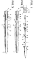
- Figure 1 is a view showing a mode in which an optical fiber cable C is inserted into an optical fiber connector in the prior art
- Figs. 2 and 3 are cross-sectional views showing how the optical fiber connector is assembled
- Fig. 4 is a cross-sectional view of the optical fiber cable when assembled.
- the optical fiber cable C consists of a cable core E comprised of a core and a cladding, both made of silica based glass, an inner coating layer P coated on the cable core E, and an outer coating layer S coated on the inner coating layer P.
- the diameter of the core is 10 ⁇ m, and the diameter of the cladding is 125 ⁇ m.
- the inner coating layer P is formed of a polyaramid fiber such as Kevlar (trademark of Du Pont Corporation), and the outer coating layer S is formed of PVC.
- the cable core E of the optical fiber cable C is inserted into a ferrule F, a spring G is fitted over the cable core E and the ferrule F, a support H is fitted over the spring G, and a projection L of the support H is fitted into a fitting groove M of a plug hole K, to fix the support H thereat.
- the inner coating layer P next to the cable core E is peeled back and then pulled forward and over a knurled portion N of the support H, a cylinder Q of a pinch member D is fitted over the portion of the inner coating layer P fitted over the knurled portion N and fastened thereat to sandwich the inner coating layer P between the pinch member D and the support H.
- the outer coating layer S of the optical fiber cable C is fitted over a pinch portion R of the pinch member D, and as shown in Fig. 3, a cylinder T is fitted over the outer coating layer S and fastened from the outside as shown by arrows to sandwich the outer coating layer S between the cylinder T and the pinch member D, to thereby pinch-fasten the optical fiber cable C to the pinch member D.
- the pinch member D is inserted into an opening B of a connector cover A, made of an elastic material such as a rubber, and then a cap X is fitted over the connector cover A, to thus complete the connection of the optical fiber cable C to the optical fiber connector.
- a stop edge W having an inner diameter d 2 which is smaller than an outer diameter d 1 of the pinch member D, is provided at an insertion opening V of the opening B and projects inward to prevent a unintentional withdrawal of the pinch member D after it is inserted into the opening B of the connector cover A.
- This prior art optical fiber connector suffers from the following disadvantages.
- the provision of the stop edge W projected inward of the opening B requires the application of a strong pressure, to forcibly press the pinch member D into the opening B.
- the cover A is formed of an elastic material such as a rubber, and accordingly, this forcible insertion of the pinch member D into the opening B is difficult and may damage the inner wall of the opening B.
- the prior art connection of the optical fiber cable to the optical fiber connector suffers from a low work efficiency, and requires a high level of skill. Accordingly, an automatic connection of the optical fiber cable to the optical fiber connector is practically impossible.
- WO-A-86/00423 shows the features of the first part of present claim 1.
- An object of the present invention is to provide an optical fiber connector in which a pinch member is easily inserted into an opening of a connector cover and is not easily withdrawn therefrom, to thus improve the efficiency of assembly.
- Another object of the present invention is to provide an optical fiber connector enabling an automatic connection of an optical fiber cable thereto.
- an optical fiber connector according to claim 1.
- the fastening ring is made of a plastically deformable material such as metal or thermoplastics.
- the fastening ring may be mounted on an inner wall of the opening.
- the fastening ring may also be mounted on an outer wall of the connector cover at the opening.
- the fastening ring may be embedded in the connector cover at the opening. In all cases, the fastening ring is integrated with the connector cover.
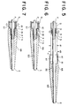
- Figures 5 is a sectional view of an optical fiber connector of an embodiment in accordance with the present invention
- Figs. 6 and 7 are sectional views showing the assembling of the optical fiber connector.
- elements having reference numerals identical to those in Figs. 1 to 4 indicate corresponding elements in Figs. 1 to 4.
- the inner diameter d 3 of the fastening ring A1 is slightly larger than the diameter d 1 of the pinch member D to facilitate the insertion of the pinch member D into the fastening ring Al.
- the fastening ring A1 is fastened at a portion of the cylinder Q of the pinch member D to thereby fix the pinch member D in the opening B of the connector cover AA, and as a result, the pinch member D can not be unintentionally withdrawn from the opening B.
- the connector cover AA has the opening B1 in which the first cable fixing means including the support H, the cylinder portion Q and the frame J, is fitted when the connector is assembled, a first hole B2 in which the second cable fixing means including the pinch member D and the cylinder T is fitted, and a second hole B3 which passes over the optical fiber cable C.
- stop edge W inserted into the opening is omitted from the optical fiber connector in the present invention.
- the fastening ring A1 formed of a force deformation material such as metal or thermoplastics can be provided on an outer wall, or the inner wall (as shown in Fig. 5), of the connector cover AA formed of an elastic material by molding, in each case so as to be formed as an integrated part of the connector cover AA, or can be embedded in the connector cover AA, so as to be formed as an integral part of the connector cover AA.
- the omission of the stop edge W eliminates any bending of the cover A made of an elastic material when the pinch member D is inserted into the opening B thereof, and thus facilitates the insertion of the pinch member D.
- the fastening ring A1 is easily fastened, provides a firm pinching of the pinch member D, and prevents an unintentional withdrawal of the optical fiber cable C from the optical fiber connector.
- the connecting and assembling operation of the present invention does not require any cumbersome or complex procedures, and accordingly, the connecting and assembling operation can be automated.
- the present invention is not limited to the connection of such optical fiber, and can be applied to other optical fibers such as a multi-mode optical fiber.
Landscapes
- Physics & Mathematics (AREA)
- General Physics & Mathematics (AREA)
- Optics & Photonics (AREA)
- Mechanical Coupling Of Light Guides (AREA)
Claims (5)
- Connecteur à fibres optiques pour la connexion d'un câble de fibres optiques (C) comprenant un noyau de câble (E), une couche de revêtement interne (P) formée sur le noyau de câble et une couche de revêtement externe (S) formée sur la couche de câble interne, comprenant :une bague (F) dans laquelle est inséré ledit noyau de câble (E);un premier moyen de fixation de câble (N, Q), comprenant une portion de manchon externe (Q), pour fixer ladite couche de revêtement interne (P);un second moyen de fixation de câble (R, T) pour fixer ladite couche de revêtement externe (S); etun couvercle de connecteur (AA) ayant un passage traversant comprenant, dans l'ordre le long du passage, une ouverture (B1) dans laquelle peut être adjusté ledit premier moyen de fixation de câble (N, Q), un premier trou (B2) dans lequel peut être ajusté ledit second moyen de fixation (R, T) et un second trou (B3) pour passer au-dessus dudit câble de fibres optiques (C);caractérisé en ce que le corps dudit couvercle de connecteur (AA) est en un matériau élastique et en ce que le couvercle de connecteur (AA) comprend de plus une bague de fixation (A1) en matériau plastiquement déformable intégralement formée avec le corps dudit couvercle de connecteur (AA), prévu autour de ladite ouverture (B), l'ouverture (B) ayant un diamètre supérieur au diamètre externe de ladite portion de manchon (Q) et audit second moyen de fixation de câble (R, T) et pouvant être fixée par une déformation par force dirigée vers l'intérieur appliquée de l'extérieur dudit couvercle de connecteur (AA) pour réaliser un pincement ferme de la portion de manchon (Q), après que ledit second moyen de fixation de câble (R, T) et ledit premier moyen de fixation de câble (N, Q) ont été ajustés respectivement dans ledit premier trou (B2) et ladite ouverture (B1), pour empêcher de la sorte au premier moyen de fixation de câble (N, Q) d'être retiré de l'ouverture (B1).
- Connecteur à fibres optiques selon la revendication 1, dans lequel la bague de fixation précitée (A1) est réalisée en métal ou en matière thermoplastique.
- Connecteur à fibres optiques selon la revendication 2, dans lequel la bague de fixation précitée (A1) forme la paroi interne du couvercle de connecteur (AA) à l'ouverture précitée (B1).
- Connecteur à fibres optiques selon la revendication 2, dans lequel la bague de fixation précitée (A1) forme la paroi externe du couvercle de connecteur précité (AA) à l'ouverture précitée (B1).
- Connecteur à fibres optiques selon la revendication 2, dans lequel la bague de fixation précitée (A1) est enfouie dans le corps du couvercle de connecteur précité (AA) à l'ouverture précitée (B1).
Applications Claiming Priority (2)
| Application Number | Priority Date | Filing Date | Title |
|---|---|---|---|
| JP2182165A JP2813432B2 (ja) | 1990-07-10 | 1990-07-10 | 光コネクタカバー |
| JP182165/90 | 1990-07-10 |
Publications (2)
| Publication Number | Publication Date |
|---|---|
| EP0466464A1 EP0466464A1 (fr) | 1992-01-15 |
| EP0466464B1 true EP0466464B1 (fr) | 1997-05-14 |
Family
ID=16113491
Family Applications (1)
| Application Number | Title | Priority Date | Filing Date |
|---|---|---|---|
| EP91306234A Expired - Lifetime EP0466464B1 (fr) | 1990-07-10 | 1991-07-09 | Connecteur à fibre optique |
Country Status (6)
| Country | Link |
|---|---|
| US (1) | US5276753A (fr) |
| EP (1) | EP0466464B1 (fr) |
| JP (1) | JP2813432B2 (fr) |
| CA (1) | CA2046516C (fr) |
| DE (1) | DE69126070T2 (fr) |
| ES (1) | ES2103779T3 (fr) |
Families Citing this family (3)
| Publication number | Priority date | Publication date | Assignee | Title |
|---|---|---|---|---|
| JPH0688904B2 (ja) * | 1984-12-28 | 1994-11-09 | 旭化成工業株式会社 | ウイルスに対する増殖抑制剤 |
| US5781681A (en) * | 1995-11-22 | 1998-07-14 | The Whitaker Corporation | Bend limiting strain relief boot |
| CN104007518A (zh) * | 2014-06-24 | 2014-08-27 | 上海鸿辉光通科技股份有限公司 | 一种sc型光纤活动连接器及其组装方法 |
Family Cites Families (7)
| Publication number | Priority date | Publication date | Assignee | Title |
|---|---|---|---|---|
| US4339171A (en) * | 1978-02-21 | 1982-07-13 | Bunker Ramo Corporation | Fiber optic cable retainer member |
| FR2454108A1 (fr) * | 1979-02-23 | 1980-11-07 | Alliance Tech Ind | Dispositif d'assemblage d'une fibre optique avec un tube metallique peripherique |
| DE2943180C2 (de) * | 1979-10-25 | 1986-04-24 | Bunker Ramo Corp., Oak Brook, Ill. | Lichtleiter-Steckverbinder |
| US4447121A (en) * | 1981-11-06 | 1984-05-08 | Amp Incorporated | Connector for fiber optic member |
| US4930856A (en) * | 1986-02-14 | 1990-06-05 | Pilling Co. | Termination for flexible light-transmitting cables |
| CA1314740C (fr) * | 1988-05-06 | 1993-03-23 | Hiroshi Okada | Bouchon pour cable de fibres optiques |
| US5073044A (en) * | 1990-10-31 | 1991-12-17 | Amp Incorporated | Right angle strain relief for optical fiber connector |
-
1990
- 1990-07-10 JP JP2182165A patent/JP2813432B2/ja not_active Expired - Fee Related
-
1991
- 1991-07-09 ES ES91306234T patent/ES2103779T3/es not_active Expired - Lifetime
- 1991-07-09 DE DE69126070T patent/DE69126070T2/de not_active Expired - Fee Related
- 1991-07-09 CA CA002046516A patent/CA2046516C/fr not_active Expired - Fee Related
- 1991-07-09 EP EP91306234A patent/EP0466464B1/fr not_active Expired - Lifetime
- 1991-07-09 US US07/725,798 patent/US5276753A/en not_active Expired - Fee Related
Non-Patent Citations (1)
| Title |
|---|
| wo86/00423 * |
Also Published As
| Publication number | Publication date |
|---|---|
| EP0466464A1 (fr) | 1992-01-15 |
| US5276753A (en) | 1994-01-04 |
| ES2103779T3 (es) | 1997-10-01 |
| CA2046516A1 (fr) | 1992-01-11 |
| JPH0469606A (ja) | 1992-03-04 |
| DE69126070T2 (de) | 1997-08-28 |
| DE69126070D1 (de) | 1997-06-19 |
| JP2813432B2 (ja) | 1998-10-22 |
| CA2046516C (fr) | 2001-09-11 |
Similar Documents
| Publication | Publication Date | Title |
|---|---|---|
| US10036859B2 (en) | Cable termination assembly and method for connectors | |
| US5862282A (en) | Optical connector plug and optical connector | |
| US4679895A (en) | Adhesiveless optical fiber connector | |
| AU680878B2 (en) | Pull-proof, modular fiber optic connector system | |
| US7785017B2 (en) | Strain-relief assemblies and methods for a field-installable fiber optic connector | |
| US6419402B1 (en) | Fiber optic connector and method for assembling | |
| US20030021548A1 (en) | Ferrule boot for optical connectors | |
| EP0690320A1 (fr) | Connecteur à fibre optique et méthode de sa production | |
| CA2120078A1 (fr) | Connecteur optique | |
| US20060177182A1 (en) | Optical fiber connector component and optical fiber connector using the same | |
| AU2015320164B2 (en) | Optical fiber connector and assembly method therefor | |
| EP1491925B1 (fr) | Ensemble connecteur pour câbles à fibers optiques avec soulagement de traction | |
| US6565264B1 (en) | Pin and socket fiber optic termini | |
| US5276753A (en) | Optical fiber connector | |
| US5436993A (en) | Multiple connector for multi-fibre optic ribbons | |
| US12265266B2 (en) | Fiber optic connectors having a sealing membrane disposed on the connector housing | |
| US20240369781A1 (en) | Optical fiber cable with optical connector, method for manufacturing optical fiber cable with optical connector, and optical connector | |
| AU2021376247B2 (en) | Fiber optic connectors having an internal retention body | |
| US11686913B2 (en) | Fiber optic cable assemblies and connector assemblies having a crimp ring and crimp body and methods of fabricating the same | |
| US20240369777A1 (en) | Fiber optic connectors having an internal retention body | |
| JPH055522Y2 (fr) | ||
| CN120949388A (zh) | 一种光连接器 | |
| JPS62121412A (ja) | 光フアイバコネクタ | |
| JPH0473841B2 (fr) |
Legal Events
| Date | Code | Title | Description |
|---|---|---|---|
| PUAI | Public reference made under article 153(3) epc to a published international application that has entered the european phase |
Free format text: ORIGINAL CODE: 0009012 |
|
| AK | Designated contracting states |
Kind code of ref document: A1 Designated state(s): DE ES FR GB IT SE |
|
| 17P | Request for examination filed |
Effective date: 19920226 |
|
| 17Q | First examination report despatched |
Effective date: 19930812 |
|
| GRAG | Despatch of communication of intention to grant |
Free format text: ORIGINAL CODE: EPIDOS AGRA |
|
| GRAH | Despatch of communication of intention to grant a patent |
Free format text: ORIGINAL CODE: EPIDOS IGRA |
|
| GRAH | Despatch of communication of intention to grant a patent |
Free format text: ORIGINAL CODE: EPIDOS IGRA |
|
| GRAA | (expected) grant |
Free format text: ORIGINAL CODE: 0009210 |
|
| AK | Designated contracting states |
Kind code of ref document: B1 Designated state(s): DE ES FR GB IT SE |
|
| ITF | It: translation for a ep patent filed | ||
| REF | Corresponds to: |
Ref document number: 69126070 Country of ref document: DE Date of ref document: 19970619 |
|
| ET | Fr: translation filed | ||
| REG | Reference to a national code |
Ref country code: ES Ref legal event code: FG2A Ref document number: 2103779 Country of ref document: ES Kind code of ref document: T3 |
|
| PLBE | No opposition filed within time limit |
Free format text: ORIGINAL CODE: 0009261 |
|
| STAA | Information on the status of an ep patent application or granted ep patent |
Free format text: STATUS: NO OPPOSITION FILED WITHIN TIME LIMIT |
|
| 26N | No opposition filed | ||
| PGFP | Annual fee paid to national office [announced via postgrant information from national office to epo] |
Ref country code: ES Payment date: 19990719 Year of fee payment: 9 |
|
| PG25 | Lapsed in a contracting state [announced via postgrant information from national office to epo] |
Ref country code: ES Free format text: LAPSE BECAUSE OF NON-PAYMENT OF DUE FEES Effective date: 20000710 |
|
| REG | Reference to a national code |
Ref country code: GB Ref legal event code: IF02 |
|
| PGFP | Annual fee paid to national office [announced via postgrant information from national office to epo] |
Ref country code: GB Payment date: 20020703 Year of fee payment: 12 |
|
| PGFP | Annual fee paid to national office [announced via postgrant information from national office to epo] |
Ref country code: SE Payment date: 20020705 Year of fee payment: 12 |
|
| PGFP | Annual fee paid to national office [announced via postgrant information from national office to epo] |
Ref country code: FR Payment date: 20020709 Year of fee payment: 12 |
|
| PGFP | Annual fee paid to national office [announced via postgrant information from national office to epo] |
Ref country code: DE Payment date: 20020717 Year of fee payment: 12 |
|
| PG25 | Lapsed in a contracting state [announced via postgrant information from national office to epo] |
Ref country code: GB Free format text: LAPSE BECAUSE OF NON-PAYMENT OF DUE FEES Effective date: 20030709 |
|
| PG25 | Lapsed in a contracting state [announced via postgrant information from national office to epo] |
Ref country code: SE Free format text: LAPSE BECAUSE OF NON-PAYMENT OF DUE FEES Effective date: 20030710 |
|
| PG25 | Lapsed in a contracting state [announced via postgrant information from national office to epo] |
Ref country code: DE Free format text: LAPSE BECAUSE OF NON-PAYMENT OF DUE FEES Effective date: 20040203 |
|
| EUG | Se: european patent has lapsed | ||
| GBPC | Gb: european patent ceased through non-payment of renewal fee |
Effective date: 20030709 |
|
| PG25 | Lapsed in a contracting state [announced via postgrant information from national office to epo] |
Ref country code: FR Free format text: LAPSE BECAUSE OF NON-PAYMENT OF DUE FEES Effective date: 20040331 |
|
| REG | Reference to a national code |
Ref country code: ES Ref legal event code: FD2A Effective date: 20010810 |
|
| REG | Reference to a national code |
Ref country code: FR Ref legal event code: ST |
|
| PG25 | Lapsed in a contracting state [announced via postgrant information from national office to epo] |
Ref country code: IT Free format text: LAPSE BECAUSE OF NON-PAYMENT OF DUE FEES;WARNING: LAPSES OF ITALIAN PATENTS WITH EFFECTIVE DATE BEFORE 2007 MAY HAVE OCCURRED AT ANY TIME BEFORE 2007. THE CORRECT EFFECTIVE DATE MAY BE DIFFERENT FROM THE ONE RECORDED. Effective date: 20050709 |