EP0466478A2 - Système d'imprimante - Google Patents
Système d'imprimante Download PDFInfo
- Publication number
- EP0466478A2 EP0466478A2 EP91306260A EP91306260A EP0466478A2 EP 0466478 A2 EP0466478 A2 EP 0466478A2 EP 91306260 A EP91306260 A EP 91306260A EP 91306260 A EP91306260 A EP 91306260A EP 0466478 A2 EP0466478 A2 EP 0466478A2
- Authority
- EP
- European Patent Office
- Prior art keywords
- print data
- expression
- printing
- multivalued
- picture elements
- Prior art date
- Legal status (The legal status is an assumption and is not a legal conclusion. Google has not performed a legal analysis and makes no representation as to the accuracy of the status listed.)
- Withdrawn
Links
Images


Classifications
-
- G—PHYSICS
- G06—COMPUTING OR CALCULATING; COUNTING
- G06K—GRAPHICAL DATA READING; PRESENTATION OF DATA; RECORD CARRIERS; HANDLING RECORD CARRIERS
- G06K15/00—Arrangements for producing a permanent visual presentation of the output data, e.g. computer output printers
- G06K15/02—Arrangements for producing a permanent visual presentation of the output data, e.g. computer output printers using printers
- G06K15/12—Arrangements for producing a permanent visual presentation of the output data, e.g. computer output printers using printers by photographic printing, e.g. by laser printers
- G06K15/1238—Arrangements for producing a permanent visual presentation of the output data, e.g. computer output printers using printers by photographic printing, e.g. by laser printers simultaneously exposing more than one point
- G06K15/1242—Arrangements for producing a permanent visual presentation of the output data, e.g. computer output printers using printers by photographic printing, e.g. by laser printers simultaneously exposing more than one point on one main scanning line
- G06K15/1247—Arrangements for producing a permanent visual presentation of the output data, e.g. computer output printers using printers by photographic printing, e.g. by laser printers simultaneously exposing more than one point on one main scanning line using an array of light sources, e.g. a linear array
-
- B—PERFORMING OPERATIONS; TRANSPORTING
- B41—PRINTING; LINING MACHINES; TYPEWRITERS; STAMPS
- B41J—TYPEWRITERS; SELECTIVE PRINTING MECHANISMS, i.e. MECHANISMS PRINTING OTHERWISE THAN FROM A FORME; CORRECTION OF TYPOGRAPHICAL ERRORS
- B41J2/00—Typewriters or selective printing mechanisms characterised by the printing or marking process for which they are designed
- B41J2/435—Typewriters or selective printing mechanisms characterised by the printing or marking process for which they are designed characterised by selective application of radiation to a printing material or impression-transfer material
Definitions
- the present invention relates to a printer system capable of multivalued expression per picture element.
- the printing means may be a line head, an optical scanner or the like which has at least one active element.
- the electrophotographic line printer comprises a charger, a line head, a developing machine and a transfer machine located opposite to a photosensitive drum that is the image bearing body.
- the charger charges the circumference of the photosensitive drum with a voltage.
- a plurality of active elements mounted on the line head selectively emit light onto the charged drum circumference, forming a latent image thereon.
- the latent image is developed by the developing machine that uses a toner as its developing solution.
- the developed image is transferred by the transfer machine onto printing paper.
- LEDs light emitting diodes
- One disadvantage of the LEDs is that they tend to differ in characteristics when produced in large quantities. As a result, it is difficult to manufacture a line head with LEDs that provide uniform light emissions.
- One envisaged solution to this problem is the use of edge emission type EL (electro-luminescent) devices as the active elements of the line head.
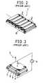
- Figs. 2 and 3 illustrate prior art line heads utilizing edge emission type EL devices. As depicted in Fig. 3, an edge emission type EL device 2 on a line head 1 has a thin film active layer 3 sandwiched from above and below with dielectric layers 4 and 5.
- the thin film active layer 3 is made of zinc sulfide and other ingredients including active elements.
- the dielectric layers 4 and 5 are in turn sandwiched from above and below with flat electrodes 6 and 7.
- a flatly polarized light emission comes out of the edge of the active layer 3.
- the intensity of the emission from the edge emission type EL device can be about 100 times as high as that of conventional EL devices that emit light from their top.
- a plurality of edge emission type EL devices 2 of the above-mentioned construction may be mounted on a substrate 8 through the use of known thin film technology or the like. When supplemented with a rod lens array, not shown, the EL device arrangement forms the line head 1.
- the line head 1 has each of its edge emission type EL devices 2 connected via a switching element to an AC power source 9. Then, the line head 1 is positioned, along with the charger, developing machine and transfer machine, opposite to the scanned surface of the photosensitive body.
- One disadvantage of this kind of edge emission type EL printer is that its edge emission type EL devices 2 provide extremely flat outgoing beams with their aspect ratio exceedingly high, which must be corrected using suitable means.
- An edge emission type EL printer 10 has an interface 12 connected to a printer controller 11 of a data processing apparatus, not shown, such as a word processor or a computer with a built-in print data setting means.
- the interface 12 is also connected to a timing controller 17 via a control circuit 16.
- the control circuit 16 is connected to two address counters 13 and 14 and a reference clock generator 15.
- the interface 12 is connected via a first data processing circuit 24 to two RAM's 22 and 23 that are line memories whose inputs and outputs are connected to three-state circuits 18 through 21.
- the RAM's 22 and 23 are also connected via a selector 25 to the control circuit 16 and the address counters 13 and 14.
- the RAM's 22 and 23 are connected via the three-state circuits 20 and 21 to a second data processing circuit 26 to which the timing controller 17 is connected.
- the data processing circuit 26 is connected in parallel to shift registers 31 l - 31 q .
- the shift registers 31 l - 31 q are in turn connected via latches 27 l - 27 q and drivers 28 l - 28 q to block electrodes 30 l - 30 n of a line head 29 that serves as printing means.
- the timing controller 17 is connected to a common driver 33, to the latches 27 l - 27 q and to the shift registers 31 l - 31 q .
- the common driver 33 is connected to common electrodes 32 l - 32 m of the line head 29.
- the circuit parts 13 through 33 constitute the printing means.
- the line head 29 has m x n edge emission type EL devices 2 counted thereon.
- the edge emission type EL printer 10 of the above-described construction has its first data processing circuit 24 to compress print data per primary scanning line through re-arrangement or other techniques.
- the print data contains clock signals that are input from the printer controller 11 via the interface 12.
- the compressed print data is stored temporarily in either of the RAM's 22 and 23 while one primary scanning line is being printed. Simultaneously, the other RAM 23 or 22 outputs the previously and temporarily stored print data at a high speed.
- Selection of either the RAM 22 or 23 for temporary storage of the print data is carried out by the selector 25 that operates on the timing signal coming from the printer controller 11 into the address counter 13.
- Output of the print data from the RAM 22 or 23 is executed by the control circuit 16 and the address counter 14, the two circuits operating synchronously on a high-speed output reference clock signal coming from the reference clock generator 15.
- the output print data is processed again by the second data processing circuit 26 into a print-ready format. From the second data processing circuit 26, the print data is output consecutively to the shift registers 31 l - 31 q and held by the latches 27 l - 27 q .
- the parts 31, 27 and the common driver 33 are controlled by the timing controller 17.
- the block electrodes 30 l -30 n and the common electrodes 32 l - 32 m respectively output low- and high-voltage driving pulses predetermined numbers of times to the line head 29.
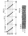
- the edge emission type EL printer 10 applies a plurality of driving pulses to the line head 29 during a time T0 for drawing one primary scanning line. This operation is repeated during the time T0 so that the line head 29 will repeat its line emission for the width of one primary scanning line.
- One emission by one edge emission type EL device 2 forms a flat picture element 34.
- a plurality of flat picture elements 34 are formed in the secondary scanning direction within a picture element region 35.
- a substantially square picture element 36 is formed, as illustrated in Fig. 7, using the flat beams of emissions by the edge emission type EL devices 2.
- the primary scanning line edges are smoothed so that an image of high quality is printed.
- the edge emission type EL printer 10 repeats non-emissions and full-emissions of its EL devices 2 within each picture element region 35 in order to print the black-and-white picture elements 36.
- This applicant has also proposed an improved edge emission type EL printer in Japanese Patent Application No. 1-97085. This printer provides half tone expression by reducing the number of picture elements in the manner desired within each picture element region.
- a further improved edge emission type EL printer has been proposed by this applicant in Japanese Patent Application No. 1-280417. The latter printer is capable of smoothing the edges of the images to be printed.
- printers work as follows. For example, when a half tone image is to be expressed with four emissions forming one picture element 36, black-and-white picture elements 36 shown in Figs. 8 (a) and 8 (d) are supplemented with half tone picture elements 37 each comprising one or three picture elements 34 which, as depicted in Figs. 8 (b) and 8 (c), are generated with one or three emissions by the EL device 2 within each picture element region 35.
- the picture elements 36 and 37 together constitute a graduated print image of high resolution with a different density per picture element.
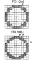
- black-and-white picture elements 36 shown in Figs. 9 (a) and 9 (d) are supplemented with smoothing picture elements 38 each comprising two picture elements 34 which, as depicted in Figs. 9 (b) and 9 (c), are generated with two emissions by the EL device 2 within each picture element region 35.
- smoothing picture elements 38 are positioned on the edges of an image that contains binary picture elements 36, as illustrated in Fig. 10 (a). The result is a smooth edge image of Fig. 10 (b) with no degradation in resolution.
- printer systems capable of multivalued expression internally store beforehand the formation of each picture element as print data of multiple bits, and control the EL devices 2 constituting each picture element for emission according to the print data.
- binary picture elements 36 are supplemented with the picture elements 37 and 38 for multivalued expression, as shown in Figs. 8 and 9, the black-and-white binary picture elements 36 are represented by two-bit print data (0, 0) - (l, l) while the multivalued picture elements 37 and 38 are represented by print data (0, l) - (l, 0).
- each EL device 2 operates in one of two ways: non-emission or full-emission.
- the print data that controls this operation is represented by either l or 0 per bit.
- the above-described printer system that uses multivalued picture elements 37 and 38 in addition to black-and-white picture elements 36 is capable of printing an image in such multivalued expression as half tone printing or smoothing printing. In practice, however, this printer system often prints images in binary expression alone.
- the above printer system stores its print data about black-and-white binary elements 36 not in single bits -- which are sufficient for the purpose -- but in multiple bits. This connotes that it takes more time to perform the data processing involved such as data transfer and temporary storage, with the result that binary images are formed at lower speeds than in the binary expression setup.
- a printer system comprising: printing means having at least one active element for multivalued expression in units of picture elements, the printing means creating an image in accordance with multiple-bit print data that are input; print data setting means for setting the print data for control over the operation of the active elements for each picture element, the print data being set in one-bit format for binary expression and in multiple-bit format for multivalued expression; data converting means for converting one-bit print data for binary expression into the same number of bits as in the print data for multivalued expression, the one-bit print data being output by the print data setting means; and an interface for inputting to the printing means both the binary expression print data of multiple bits coming from the data converting means and the multivalued expression print data of multiple bits coming from the print data setting means.
- the printer system of the above construction allows the printing means operating with multiple-bit print data to be driven with one-bit print data.
- the printer system processes multiple-bit print data in the same manner as conventional printers; when printing images of binary expression, the printer system handles print data in one-bit format so as to speed up such data processing tasks as data transfer and temporary storage.
- An edge emission type EL printer 39 practiced as the first embodiment of the invention has substantially the same construction as the prior art edge emission type EL printer 10 mentioned above, and is capable of multivalued expression such as half tone and smoothing printing.
- the edge emission type EL printer 39 has multivalued expression print data represented in two bits.
- Two data lines 40 and 41 are interposingly connected between the printer controller 11 and the interface 12 via a data converting circuit 42 that acts as data converting means.
- the switchable input terminals of a selector 44 are connected to the data lines 40 and 41, the selector being connected to a changeover switch 43.
- the output terminal of the selector 44 is connected to the data line 41 alone.
- edge emission type EL printer 39 two-bit print data for multivalued expression are transferred over the two data lines 40 and 41, while one-bit print data for binary expression are transferred over the data line 40.
- the printing-related circuits downstream of the interface 12 operate with two-bit print data.
- the edge emission type EL printer 39 of the above construction performs printing of multivalued expression such as a half tone and smoothing printing using multivalued expression picture elements 37 and 38 shown in Figs. 8 and 9.
- the changeover switch 43 causes the selector 44 to permit data input and output over the data line 41.
- the two-bit print data for multivalued expression, (0, 0), (0, l), (l, 0) and (l, l) are input over the data lines 40 and 41 from the printer controller 11 of a data processing apparatus, not shown, in a word processor, a computer or the like containing print data setting means. These two-bit print data are transferred over the data lines 40 and 41 to the interface 12 without being converted by the data converting circuit 42.
- the two-bit print data are used for multivalued expression printing such as a half tone and smoothing printing.
- the changeover switch 43 causes the selector 44 to connect the input over the data line 40 to the output over the data line 41.
- One-bit print data for binary expression (0, 0) - (l, l)
- These one-bit print data are divided by the data converting circuit 42 into data items for the two data lines 40 and 41. That is, the data are converted to pseudo-two-bit print data such as (0, 0) - (l, l).
- the converted data are transferred to the interface 12 for use in binary expression printing.
- the edge emission type EL printer 39 drives the printing means that operates with two-bit print data also with one-bit print data.
- the data processing apparatus not shown, which outputs print data from the printer controller 11 to the interface 12, need only process one-bit print data when binary expression printing is to be conducted. There is no need to process print data of the same number of bits for binary expression as for multivalued expression, as required of conventional printer systems. With less time needed to process print data, the speed at which to print binary images is significantly improved.
- the edge emission type EL printer 39 processes multiple-bit print data for multivalued expression printing (e.g., a half tone and smoothing printing) in the same manner as conventional printer systems, and processes the print data as one-bit data for binary expression at higher speeds.
- This two-tier approach allows the printer system to implement both multivalued expression printing such as a half tone and smoothing printing and high-speed binary expression printing concurrently, taking advantage of the benefits of both modes of printing.
- the edge emission type EL printer 39 practiced as the second embodiment of the invention has substantially the same construction as the prior art edge emission type EL printer 10 mentioned above, and is capable of multivalued expression such as a half tone and smoothing printing.
- Print data are output from the printer controller 11 of a data processing apparatus, not shown, in a word processor, a computer or the like containing print data setting means. These data are in the two-bit format common to that of the data (0, 0) - (l, l) for a half tone and smoothing printing.
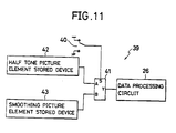
- the second data processing circuit 26 is connected via a selector 41 to a half tone picture element stored device 42 and a smoothing picture element stored device 43.
- the selector 41 serves as pattern switching means to which a changeover switch 40 is connected, and the devices 42 and 43 are each print pattern storing means.
- the half tone picture element stored device 42 and the smoothing picture element stored device 43 contain four picture elements 36 and 37 for half tone printing as well as four picture elements 36 and 38 for smoothing printing, the picture elements being shown in Figs. 8 and 9.
- An address common to the two picture element stored devices 42 and 43 is set using two-bit data such as (0, 0) - (l, l).
- the changeover switch 40 causes the selector 41 to connect the half tone picture element stored device 42 with the data processing circuit 26 illustratively where half tone printing is desired.
- the selector 41 connects the smoothing picture element stored device 43 with the data processing circuit 26. Then those picture elements 36 and 38 for smoothing expression which correspond to two-bit print data (0, 0) - (l, l) are sent to the data processing circuit 26 to carry out smoothing printing.
- the edge emission type EL printer 39 prints images in two kinds of multivalued expression using a total of six picture elements 36 through 38.
- the data processing involved is performed using two-bit print data.
- the edge emission type EL printer 39 is therefore capable of setting print data for a plurality of kinds of multivalued expression using the same number of bits as that of print data for one kind of multivalued expression. Because there is no need to raise the number of bits of print data every time another kind of multivalued expression is added, a plurality of kinds of multivalued expression are made available with no deterioration in the speed of printing.
- the invention has been described in the form of the edge emission type EL printer 39, the invention is not limited to this type of printer system alone. Alternatively, the invention may be applied to diverse kinds of printer systems capable of multivalued expression in units of picture elements.
- One alternative example of such printer systems is a laser printer that varies the intensity of a laser beam to change the diameter of each picture element.
- Another alternative example is a thermal printer that varies the intensity of electrically generated heat to change the density of picture elements.
Landscapes
- Physics & Mathematics (AREA)
- Engineering & Computer Science (AREA)
- Optics & Photonics (AREA)
- General Engineering & Computer Science (AREA)
- General Physics & Mathematics (AREA)
- Theoretical Computer Science (AREA)
- Color, Gradation (AREA)
- Printers Or Recording Devices Using Electromagnetic And Radiation Means (AREA)
Applications Claiming Priority (4)
| Application Number | Priority Date | Filing Date | Title |
|---|---|---|---|
| JP2182270A JPH0469256A (ja) | 1990-07-10 | 1990-07-10 | プリンタシステム |
| JP182271/90 | 1990-07-10 | ||
| JP182270/90 | 1990-07-10 | ||
| JP2182271A JPH0469257A (ja) | 1990-07-10 | 1990-07-10 | プリンタシステム |
Publications (1)
| Publication Number | Publication Date |
|---|---|
| EP0466478A2 true EP0466478A2 (fr) | 1992-01-15 |
Family
ID=26501129
Family Applications (1)
| Application Number | Title | Priority Date | Filing Date |
|---|---|---|---|
| EP91306260A Withdrawn EP0466478A2 (fr) | 1990-07-10 | 1991-07-10 | Système d'imprimante |
Country Status (2)
| Country | Link |
|---|---|
| EP (1) | EP0466478A2 (fr) |
| KR (1) | KR920002346A (fr) |
Cited By (1)
| Publication number | Priority date | Publication date | Assignee | Title |
|---|---|---|---|---|
| EP1629983A3 (fr) * | 2004-08-24 | 2008-04-30 | Ricoh Company, Ltd. | Appareil d'impression d'image |
-
1991
- 1991-07-05 KR KR1019910011387A patent/KR920002346A/ko not_active Abandoned
- 1991-07-10 EP EP91306260A patent/EP0466478A2/fr not_active Withdrawn
Cited By (2)
| Publication number | Priority date | Publication date | Assignee | Title |
|---|---|---|---|---|
| EP1629983A3 (fr) * | 2004-08-24 | 2008-04-30 | Ricoh Company, Ltd. | Appareil d'impression d'image |
| US7453485B2 (en) | 2004-08-24 | 2008-11-18 | Ricoh Company, Ltd. | Image writing apparatus for controlling transfer of image data |
Also Published As
| Publication number | Publication date |
|---|---|
| KR920002346A (ko) | 1992-02-28 |
Similar Documents
| Publication | Publication Date | Title |
|---|---|---|
| DE3650773T2 (de) | Bilderzeugungsgerät | |
| DE19525110A1 (de) | Verfahren und Vorrichtung zur parallelen Verarbeitung von Bilddokumenten | |
| US5648810A (en) | Printer which prints with a resolution exceeding led head resolution | |
| US5384646A (en) | Marking engine for grey level printing having a high productivity image data processing mode | |
| US6184971B1 (en) | Exposure apparatus and image formation apparatus | |
| US5241324A (en) | Image printing method for edge emission type el printer | |
| US6049349A (en) | Printer having print data correction circuit | |
| EP0837426B1 (fr) | Appareil de formation d'image | |
| EP0466478A2 (fr) | Système d'imprimante | |
| EP0413529B1 (fr) | Imprimante à électroluminescence du type à émission latérale | |
| EP0393983B1 (fr) | Imprimante à EL du type à émission latérale et sa méthode d'impression | |
| JP2839810B2 (ja) | Ledプリンタにおける高密度画像形成方法 | |
| EP0393981B1 (fr) | Imprimante de lignes | |
| US4972228A (en) | Image forming apparatus with selective erase | |
| JPH09174937A (ja) | 画像形成装置および方法 | |
| JP2534364B2 (ja) | ラインヘッドの駆動方法 | |
| JP2514247B2 (ja) | ラインプリンタ | |
| JP2000085178A (ja) | 露光装置及び画像形成装置 | |
| JPH0557955A (ja) | ラインプリンタ | |
| JPH0469256A (ja) | プリンタシステム | |
| JPH0469257A (ja) | プリンタシステム | |
| JPH03142260A (ja) | 画像形成方法 | |
| JP2539938B2 (ja) | ラインプリンタ | |
| JPH03216357A (ja) | 端面発光型elプリンタ | |
| DE69319223T2 (de) | Gerät und Verfahren für die Verarbeitung von Bildaten |
Legal Events
| Date | Code | Title | Description |
|---|---|---|---|
| PUAI | Public reference made under article 153(3) epc to a published international application that has entered the european phase |
Free format text: ORIGINAL CODE: 0009012 |
|
| 17P | Request for examination filed |
Effective date: 19910722 |
|
| AK | Designated contracting states |
Kind code of ref document: A2 Designated state(s): DE FR GB IT NL SE |
|
| STAA | Information on the status of an ep patent application or granted ep patent |
Free format text: STATUS: THE APPLICATION HAS BEEN WITHDRAWN |
|
| 18W | Application withdrawn |
Withdrawal date: 19930203 |