EP0466536A2 - Elektromagnet, insbesondere für Kontaktvorrichtung - Google Patents
Elektromagnet, insbesondere für Kontaktvorrichtung Download PDFInfo
- Publication number
- EP0466536A2 EP0466536A2 EP91401651A EP91401651A EP0466536A2 EP 0466536 A2 EP0466536 A2 EP 0466536A2 EP 91401651 A EP91401651 A EP 91401651A EP 91401651 A EP91401651 A EP 91401651A EP 0466536 A2 EP0466536 A2 EP 0466536A2
- Authority
- EP
- European Patent Office
- Prior art keywords
- piece
- fixed
- frame
- hand
- core
- Prior art date
- Legal status (The legal status is an assumption and is not a legal conclusion. Google has not performed a legal analysis and makes no representation as to the accuracy of the status listed.)
- Granted
Links
Images

Classifications
-
- H—ELECTRICITY
- H01—ELECTRIC ELEMENTS
- H01F—MAGNETS; INDUCTANCES; TRANSFORMERS; SELECTION OF MATERIALS FOR THEIR MAGNETIC PROPERTIES
- H01F7/00—Magnets
- H01F7/06—Electromagnets; Actuators including electromagnets
- H01F7/08—Electromagnets; Actuators including electromagnets with armatures
- H01F7/16—Rectilinearly-movable armatures
- H01F7/1638—Armatures not entering the winding
-
- H—ELECTRICITY
- H01—ELECTRIC ELEMENTS
- H01H—ELECTRIC SWITCHES; RELAYS; SELECTORS; EMERGENCY PROTECTIVE DEVICES
- H01H50/00—Details of electromagnetic relays
- H01H50/16—Magnetic circuit arrangements
- H01H50/163—Details concerning air-gaps, e.g. anti-remanence, damping, anti-corrosion
-
- H—ELECTRICITY
- H01—ELECTRIC ELEMENTS
- H01H—ELECTRIC SWITCHES; RELAYS; SELECTORS; EMERGENCY PROTECTIVE DEVICES
- H01H50/00—Details of electromagnetic relays
- H01H50/54—Contact arrangements
- H01H50/546—Contact arrangements for contactors having bridging contacts
Definitions
- the present invention relates to an electromagnet, in particular for a contactor, with a simplified magnetic circuit.
- a known direct current electromagnet for an electrical switching device such as a contactor or relay is described in patent FR-1 051 651.
- This electromagnet comprises a coil wound on a body and associated with a magnetic circuit consisting of a fixed armature and a movable frame, the latter being able to move along a determined axis to take a rest position and a working position.
- the fixed and mobile armatures have lateral polar surfaces on the one hand, and central polar surfaces on the other, some of these surfaces being oblique to the axis of movement of the mobile armature, in order to increase the surfaces magnetically active and as a corollary to decrease the power consumed by the coil.
- the object of the invention is in particular to simplify the manufacture of an electromagnet with oblique polar surfaces of the type described while allowing satisfactory alignment and guidance of the movable armature relative to the fixed armature.
- Another aim is to simplify the elements that may be provided to materialize the air gap and contribute to the mutual alignment and guidance of the fixed and mobile armatures.
- Maintaining the movable armature is facilitated when applying on at least one face of this armature - or of the fixed armature - an airgap piece of non-magnetic material, this part having on the one hand a wall applied to a face of the armature adjacent to the lateral pole surfaces and on the other hand partitions perpendicular to said wall, situated on flanks of opposite slopes of the lateral pole surfaces and of thickness defining the air gap thereof.
- the air-gap part has at least one guide element cooperating with an element of complementary shape provided in the other frame. This arrangement facilitates rigorous alignment of the reinforcing parts, which is particularly advantageous when these are thin sheet metal parts.
- FIG 1 shows schematically and in section an electromagnet for contactor according to the invention.
- Figure 2 shows the electromagnet in exploded perspective.
- Figure 3 is an elevational view, along arrow A of Figure 2, of the armatures of the electromagnet, devoid of the air gap parts.
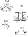
- Figure 4 shows a single cut piece of reinforcement.
- FIG. 5 is the view along arrow B of the part in FIG. 4.
- Figure 6 shows the part of Figure 4 equipped with the air gap part.
- Figure 7 is a perspective view of an air gap.
- FIG. 8 is a section of the electromagnet similar to that of FIG. 1.
- FIG. 9 shows on a larger scale the detail C of FIG. 8.
- the electromagnet 10 shown is intended to be housed in the housing of a DC contactor. It includes an excitation coil 11 wound on a plastic body 12 and associated with a magnetic circuit 13.
- the magnetic circuit comprises a cylinder head or fixed armature 14 and a movable armature 15.
- the latter can be moved from a rest position I to a working position II and vice versa (see FIG. 3), depending on the supply of the coil; the movement of the armature 15 is carried out in translation along an axis X-X.
- a contact holder 16 is fixed to the movable armature.
- the fixed frame 14 comprises a part 17 cut from a thin sheet of magnetic material and folded into a U-shape, as well as a fixed core 18 fixed to the part 17;
- the movable frame 15 comprises a part 19 identical to the part 17 and a cylindrical core 20 fixed to the part 19.
- the cores 18, 20 define a conical central pole surface for the electromagnet.
- a spring 21 is disposed in a cylindrical cavity of the movable core 20 and has its ends in abutment respectively on the core 18 and on the core 20; the function of this spring is to return the movable armature to its rest position 1.
- the coil body 12 comprises a cylindrical housing 22 in which the cores 18, 20 are housed, as well as two flanges 23, 24 adjacent to the internal surfaces of the U-shaped pieces, 17, 19.
- the flange 24 has straight edges 24a, 24b cooperating with the internal flat faces of the wings of the U of the frame part 19 to facilitate the maintenance and the guiding thereof.
- the coil body also comprises lugs 25 for fixing to the contactor housing, these lugs passing through notches formed at the bottom of the reinforcement piece 19, and a lateral extension 26 carrying connection pieces 26a for the coil.
- the contact carrier 16 is fixed to the movable frame 15 via hooks 27 passing through holes 28 in the bottom of the frame piece 19; these orifices are arranged to allow, after engagement of the hooks along the axis X-X, fixing by translation perpendicular to this axis or by quarter-turn rotation.
- the height of the part of the hooks protruding from the bottom of the frame piece 19 is small enough that this part remains contained in a recess 29 of small height provided in the thickness of the flange 24.
- Each frame piece 17, 19 is associated with a gap piece 30, respectively 31, which on the one hand provides the locally desired gap and on the other hand a reciprocal guiding effect.
- the air gap parts will be described later.
- the two cut parts 17, 19 are U-shaped and each have a core 32 constituting the aforementioned bottom and two wings 33, 34. As these parts are strictly identical, the description will only be made for part 19.
- the core 32 has, in addition to the orifices 28 already mentioned, a central orifice 35 for positioning the core and the end of a notch 37 in the wing 34 for the passage of a guide nose belonging to the part d 'air gap 30 associated with the reinforcement piece 17.
- a wing 33 of the part 19 comprises a central tooth 38 and two symmetrical lateral teeth 39, 40.
- the lateral teeth are smaller than the central tooth and are separated from the latter by a notch 41, respectively 42.
- Each tooth 38, 40 is pointed and its song presents two flanks of opposite slopes 38a, 38b; 39a, 39b; 40a, 40b (see Figure 4) which constitute the airgap surfaces of the electromagnet.
- the teeth described can of course be provided in a number different from three. The teeth are cut before or after the U-fold.
- the other wing 34 of the part 19 comprises a central hollow 43 complementary to the central tooth 38 and two symmetrical lateral hollows 44, 45 complementary to the lateral teeth 39, 40.
- the hollow 43 is separated from the hollows 44, 45 by flat teeth 46, 47 able to penetrate with play in the slots 41, 42 of the other U-shaped part.
- the air gap parts 30, 31 are made of non-magnetic material. They are preferably molded in plastic material facilitating sliding and are identical. Each comprises on the one hand one or two walls 50 (see FIG. 7) parallel to the axis XX and applied to the faces of the wing 33 (or 34), more precisely to the lateral faces of the teeth 38-40, and on the other hand partitions 51 of opposite slopes, perpendicular to the wall 50.
- the partitions 51 have a small thickness, corresponding to the desired air gap between the teeth 38-40 and the recesses 43-45, and they are applied to the songs from opposite slopes of the teeth.
- Each air gap piece 30, 31, associated with a frame has a guide nose 52 cooperating with the notch 37 of the wing of the other frame piece, to ensure alignment and mutual guidance of the frames .
- the air-gap piece 30, 31 comprises protrusions 53 penetrating into holes 54 of the frame piece 17, 19 to ensure by interlocking or snap-fastening the maintenance of the application of the air-piece piece on the piece of frame.
- the protrusions can be elastic nipples or thermowells.
- the air gaps between the various hollows and teeth of the wings of the two frames are materialized by the partitions 51 of the parts 30, 31.
- the thickness of the partitions is identical for all the teeth, but it could be differentiated.
- the relative position of the two armatures in direction A is maintained by the mutual positioning of the two cores in the housing 22 of the coil body, with possibly anti-rotation ribs and grooves provided on the movable core and in the housing.
- the wall 50 of the air-gap piece can contribute to maintaining said relative position.
- Each air-gap piece is applied to one side of the wing 33, 34, but could be arranged to cover the latter and be applied to both of its faces.
- the fixed core 18 is positioned without axial play in the orifice 35 of the reinforcing piece 19 in order to be then fixed to this piece by any usual means.
- the movable cylindrical-conical core 20 is placed on the fixed cylindrical-conical core 18 and the fixed reinforcement part 17 is placed on the part 19.
- An axial clearance j is thus automatically obtained between the core 20 and the part 17 and it suffices to fix them then by any usual assembly process at the orifice 35 as indicated at 60 with or without the addition of material to memorize the axial play in question.
Landscapes
- Physics & Mathematics (AREA)
- Electromagnetism (AREA)
- Engineering & Computer Science (AREA)
- Power Engineering (AREA)
- Electromagnets (AREA)
- Arc-Extinguishing Devices That Are Switches (AREA)
- Relay Circuits (AREA)
- Electronic Switches (AREA)
- Contacts (AREA)
- Manufacture Of Switches (AREA)
Applications Claiming Priority (2)
| Application Number | Priority Date | Filing Date | Title |
|---|---|---|---|
| FR9008932 | 1990-07-13 | ||
| FR9008932A FR2664736B1 (fr) | 1990-07-13 | 1990-07-13 | Electroaimant, notamment pour contacteur. |
Publications (3)
| Publication Number | Publication Date |
|---|---|
| EP0466536A2 true EP0466536A2 (de) | 1992-01-15 |
| EP0466536A3 EP0466536A3 (en) | 1992-03-18 |
| EP0466536B1 EP0466536B1 (de) | 1994-05-25 |
Family
ID=9398677
Family Applications (1)
| Application Number | Title | Priority Date | Filing Date |
|---|---|---|---|
| EP91401651A Expired - Lifetime EP0466536B1 (de) | 1990-07-13 | 1991-06-19 | Elektromagnet, insbesondere für Kontaktvorrichtung |
Country Status (5)
| Country | Link |
|---|---|
| EP (1) | EP0466536B1 (de) |
| AT (1) | ATE106158T1 (de) |
| DE (1) | DE69102100T2 (de) |
| ES (1) | ES2053294T3 (de) |
| FR (1) | FR2664736B1 (de) |
Family Cites Families (6)
| Publication number | Priority date | Publication date | Assignee | Title |
|---|---|---|---|---|
| DE1909856A1 (de) * | 1969-02-27 | 1970-09-10 | Merk Gmbh Telefonbau Fried | Elektromagnet mit Tauchanker |
| CH559414A5 (en) * | 1973-07-25 | 1975-02-28 | Olten Ag Elektro Apparatebau | Pot-shaped magnet with armature in switch housing - has outer wall of pot forming air gap with armature for increased attraction force |
| GB2039418A (en) * | 1979-01-10 | 1980-08-06 | Printer Ass | Electromagnetic matrix printing cell and head assembly |
| CA1151229A (en) * | 1979-09-04 | 1983-08-02 | Bendix Corporation (The) | Solenoid having a multi-piece armature |
| JPS5871605A (ja) * | 1981-10-26 | 1983-04-28 | Matsushita Electric Ind Co Ltd | 自己保持型ソレノイド |
| FR2560429B1 (fr) * | 1984-02-28 | 1987-06-19 | Telemecanique Electrique | Electro-aimant silencieux et contacteur utilisant un tel electro-aimant |
-
1990
- 1990-07-13 FR FR9008932A patent/FR2664736B1/fr not_active Expired - Fee Related
-
1991
- 1991-06-19 EP EP91401651A patent/EP0466536B1/de not_active Expired - Lifetime
- 1991-06-19 AT AT91401651T patent/ATE106158T1/de not_active IP Right Cessation
- 1991-06-19 DE DE69102100T patent/DE69102100T2/de not_active Expired - Fee Related
- 1991-06-19 ES ES91401651T patent/ES2053294T3/es not_active Expired - Lifetime
Also Published As
| Publication number | Publication date |
|---|---|
| FR2664736A1 (fr) | 1992-01-17 |
| DE69102100T2 (de) | 1994-11-03 |
| FR2664736B1 (fr) | 1994-03-11 |
| EP0466536B1 (de) | 1994-05-25 |
| EP0466536A3 (en) | 1992-03-18 |
| DE69102100D1 (de) | 1994-06-30 |
| ATE106158T1 (de) | 1994-06-15 |
| ES2053294T3 (es) | 1994-07-16 |
Similar Documents
| Publication | Publication Date | Title |
|---|---|---|
| EP0469950B1 (de) | Armbanduhrgehäuse mit auswechselbarem Deckel | |
| CA2319676C (fr) | Contacteur electromecanique | |
| CA1037086A (fr) | Contacteur | |
| CH663682A5 (fr) | Electro-aimant. | |
| FR2466844A1 (fr) | Electro-aimant comportant un noyau-plongeur muni d'un aimant monostable ou bistable | |
| FR2870492A1 (fr) | Lampe d'eclairage interieure pour vehicule | |
| EP0282377B1 (de) | Elektrische Motorgetriebeeinheit und Verfahren zu deren Montage | |
| EP1901327B1 (de) | Mechanismus mit zwei stabilen Positionen und diesen umfassende elektrische Steuervorrichtung | |
| EP0863523B1 (de) | Multipolare elektrische Schalter | |
| EP0466536B1 (de) | Elektromagnet, insbesondere für Kontaktvorrichtung | |
| EP0086698B1 (de) | Kleinschütz mit entfernbarer Hilfsschalterbaugruppe | |
| EP0469938A1 (de) | Bürstenhalter für elektrische Kollektormaschine | |
| EP0848452B1 (de) | Verbindungsmodul mit Durchverbindung von Anschlüssen mittels eines oder mehreren beweglichen leitenden Teilen | |
| CA1203825A (fr) | Dispositif amovible de verrouillage d'un contacteur dans sa position de travail | |
| FR2579369A1 (fr) | Appareil de commutation a commande electromagnetique, et procede de realisation des zones de raccordement des contacts de cet appareil | |
| EP1053554B1 (de) | Elektromagnetischer schütz | |
| CH635911A5 (fr) | Valve pour fluide a commande manuelle. | |
| CA1120978A (fr) | Contacteur equipe d'un electro-aimant dont les elements fixes sont amovibles | |
| EP1006549B1 (de) | Elektromechanisches Schaltgerät | |
| EP0200617A1 (de) | An ein Schaltgerät mit zwei Stellungen anpassbare elektrische Antriebsvorrichtung | |
| FR2485798A1 (fr) | Actionneur electromagnetique | |
| EP0551777A1 (de) | Schaltgeräte für elektromagnetische und manuelle Betätigung | |
| FR2685138A1 (fr) | Dispositif perfectionne pour le montage d'elements d'une installation electrique, traversant une paroi et assurant le menagement d'une reservation dans celle-ci. | |
| FR2576141A1 (fr) | Disjoncteur basse tension, avec verrou de maintien agence dans une chambre separee | |
| FR2752995A1 (fr) | Electroaimant a noyau plongeant utilise par exemple dans un telerupteur |
Legal Events
| Date | Code | Title | Description |
|---|---|---|---|
| PUAI | Public reference made under article 153(3) epc to a published international application that has entered the european phase |
Free format text: ORIGINAL CODE: 0009012 |
|
| 17P | Request for examination filed |
Effective date: 19910627 |
|
| AK | Designated contracting states |
Kind code of ref document: A2 Designated state(s): AT CH DE ES GB IT LI |
|
| PUAL | Search report despatched |
Free format text: ORIGINAL CODE: 0009013 |
|
| AK | Designated contracting states |
Kind code of ref document: A3 Designated state(s): AT CH DE ES GB IT LI |
|
| 17Q | First examination report despatched |
Effective date: 19930223 |
|
| GRAA | (expected) grant |
Free format text: ORIGINAL CODE: 0009210 |
|
| AK | Designated contracting states |
Kind code of ref document: B1 Designated state(s): AT CH DE ES GB IT LI |
|
| REF | Corresponds to: |
Ref document number: 106158 Country of ref document: AT Date of ref document: 19940615 Kind code of ref document: T |
|
| ITF | It: translation for a ep patent filed | ||
| REF | Corresponds to: |
Ref document number: 69102100 Country of ref document: DE Date of ref document: 19940630 |
|
| GBT | Gb: translation of ep patent filed (gb section 77(6)(a)/1977) |
Effective date: 19940607 |
|
| REG | Reference to a national code |
Ref country code: ES Ref legal event code: FG2A Ref document number: 2053294 Country of ref document: ES Kind code of ref document: T3 |
|
| PLBE | No opposition filed within time limit |
Free format text: ORIGINAL CODE: 0009261 |
|
| STAA | Information on the status of an ep patent application or granted ep patent |
Free format text: STATUS: NO OPPOSITION FILED WITHIN TIME LIMIT |
|
| 26N | No opposition filed | ||
| PGFP | Annual fee paid to national office [announced via postgrant information from national office to epo] |
Ref country code: AT Payment date: 19960528 Year of fee payment: 6 |
|
| PGFP | Annual fee paid to national office [announced via postgrant information from national office to epo] |
Ref country code: GB Payment date: 19960611 Year of fee payment: 6 |
|
| PGFP | Annual fee paid to national office [announced via postgrant information from national office to epo] |
Ref country code: ES Payment date: 19960613 Year of fee payment: 6 |
|
| PGFP | Annual fee paid to national office [announced via postgrant information from national office to epo] |
Ref country code: DE Payment date: 19960619 Year of fee payment: 6 |
|
| PGFP | Annual fee paid to national office [announced via postgrant information from national office to epo] |
Ref country code: CH Payment date: 19960621 Year of fee payment: 6 |
|
| PG25 | Lapsed in a contracting state [announced via postgrant information from national office to epo] |
Ref country code: GB Free format text: LAPSE BECAUSE OF NON-PAYMENT OF DUE FEES Effective date: 19970619 Ref country code: AT Effective date: 19970619 |
|
| PG25 | Lapsed in a contracting state [announced via postgrant information from national office to epo] |
Ref country code: ES Free format text: LAPSE BECAUSE OF NON-PAYMENT OF DUE FEES Effective date: 19970620 |
|
| PG25 | Lapsed in a contracting state [announced via postgrant information from national office to epo] |
Ref country code: LI Free format text: LAPSE BECAUSE OF NON-PAYMENT OF DUE FEES Effective date: 19970630 Ref country code: CH Free format text: LAPSE BECAUSE OF NON-PAYMENT OF DUE FEES Effective date: 19970630 |
|
| GBPC | Gb: european patent ceased through non-payment of renewal fee |
Effective date: 19970619 |
|
| REG | Reference to a national code |
Ref country code: CH Ref legal event code: PL |
|
| PG25 | Lapsed in a contracting state [announced via postgrant information from national office to epo] |
Ref country code: DE Free format text: LAPSE BECAUSE OF NON-PAYMENT OF DUE FEES Effective date: 19980303 |
|
| REG | Reference to a national code |
Ref country code: ES Ref legal event code: FD2A Effective date: 20000403 |
|
| PG25 | Lapsed in a contracting state [announced via postgrant information from national office to epo] |
Ref country code: IT Free format text: LAPSE BECAUSE OF NON-PAYMENT OF DUE FEES;WARNING: LAPSES OF ITALIAN PATENTS WITH EFFECTIVE DATE BEFORE 2007 MAY HAVE OCCURRED AT ANY TIME BEFORE 2007. THE CORRECT EFFECTIVE DATE MAY BE DIFFERENT FROM THE ONE RECORDED. Effective date: 20050619 |