EP0467000A1 - Chauffe-plat et son utilisation - Google Patents
Chauffe-plat et son utilisation Download PDFInfo
- Publication number
- EP0467000A1 EP0467000A1 EP90810549A EP90810549A EP0467000A1 EP 0467000 A1 EP0467000 A1 EP 0467000A1 EP 90810549 A EP90810549 A EP 90810549A EP 90810549 A EP90810549 A EP 90810549A EP 0467000 A1 EP0467000 A1 EP 0467000A1
- Authority
- EP
- European Patent Office
- Prior art keywords
- bowl
- heat
- base body
- bowl according
- shaft
- Prior art date
- Legal status (The legal status is an assumption and is not a legal conclusion. Google has not performed a legal analysis and makes no representation as to the accuracy of the status listed.)
- Withdrawn
Links
- 238000010792 warming Methods 0.000 title abstract description 6
- 239000000463 material Substances 0.000 claims abstract description 24
- 239000002131 composite material Substances 0.000 claims abstract description 18
- 238000005338 heat storage Methods 0.000 claims abstract 2
- 238000010438 heat treatment Methods 0.000 claims description 36
- 229910000831 Steel Inorganic materials 0.000 claims description 7
- 239000010959 steel Substances 0.000 claims description 7
- XAGFODPZIPBFFR-UHFFFAOYSA-N aluminium Chemical compound [Al] XAGFODPZIPBFFR-UHFFFAOYSA-N 0.000 claims description 2
- 229910052782 aluminium Inorganic materials 0.000 claims description 2
- 239000002245 particle Substances 0.000 claims 1
- 238000003860 storage Methods 0.000 abstract description 4
- 239000010410 layer Substances 0.000 description 15
- 239000011324 bead Substances 0.000 description 7
- 239000012792 core layer Substances 0.000 description 4
- 239000004020 conductor Substances 0.000 description 2
- 239000011810 insulating material Substances 0.000 description 2
- 229910001220 stainless steel Inorganic materials 0.000 description 2
- 239000010935 stainless steel Substances 0.000 description 2
- 239000011232 storage material Substances 0.000 description 2
- 210000001015 abdomen Anatomy 0.000 description 1
- 238000010276 construction Methods 0.000 description 1
- 238000010924 continuous production Methods 0.000 description 1
- 238000001816 cooling Methods 0.000 description 1
- 239000012774 insulation material Substances 0.000 description 1
- 238000004519 manufacturing process Methods 0.000 description 1
- 239000000203 mixture Substances 0.000 description 1
- 238000005580 one pot reaction Methods 0.000 description 1
Images
Classifications
-
- A—HUMAN NECESSITIES
- A47—FURNITURE; DOMESTIC ARTICLES OR APPLIANCES; COFFEE MILLS; SPICE MILLS; SUCTION CLEANERS IN GENERAL
- A47J—KITCHEN EQUIPMENT; COFFEE MILLS; SPICE MILLS; APPARATUS FOR MAKING BEVERAGES
- A47J36/00—Parts, details or accessories of cooking-vessels
- A47J36/24—Warming devices
- A47J36/2483—Warming devices with electrical heating means
Definitions
- the object of the present invention is to provide a heating bowl which does not have the disadvantages mentioned or any other.
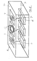
- the heating loops 4 can contain resistance bodies, which convert electrical energy into heat.
- the heating loops 4 can also be designed as inductors, which are connected to a source 6 of high-frequency energy via connections 7.
- the generators 6 are located on the lower horizontal surface 3.
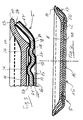
- the present heat bowl 5 is shown in a vertical section.
- a plate 10 is inserted, in which there is a dish when in use.
- the plate 10 comprises a bottom 11 (FIG. 3), at the edge of which the plate side wall 12 connects.
- the free edge 13 of the side wall 12 is shaped such that it runs practically horizontally or at least almost horizontally.
- the bottom of the plate bottom 11 is verse with a foot 14 hen, which is designed as a bead.
- This bead 14 extends along a plate section, in which the plate wall or the plate belly 12 adjoins the plate base 11.
- the composite material further comprises at least one further layer 22, which serves as the cover material of the composite material.
- this second or outer layer 22 is arranged on the outside of the base layer 21 and, among other things, it protects the core layer 21 from any mechanical stresses or damage.
- the outer layer 22 should be as good a heat conductor as possible.
- Steel, which is plated on the core layer 21, is best suited to this purpose.
- Such a steel can be a ferritic or serritic steel, in particular stainless steel of a type known per se.
- Such a steel can contain or include ferritic material.
- the base material 21 should have a thermal conductivity which is better than the thermal conductivity of the cover material 22.
- the shaft 25 in the bowl bottom 16 is designed such that the valleys 27 and 28 thereof, between which the comb 28 lies, form the end parts of the shaft 25.
- the other parts of the bowl base body 15 thus advantageously adjoin the valley parts 27 and 28 of the shaft 25 in a blunt manner.
- the middle section 30 of the bowl bottom 16 which is essentially disk-shaped, can adjoin the inner end section 27 of the shaft 25.
- Either an essentially annular outer section 31 of the base 16 or the side section 17 of the bowl base body 15 can be connected to the outer end section 28 of the shaft 25.
- the end section 27 of the shaft 25 facing the middle section 30 of the bottom section 16 is higher than the end section 28 of the shaft 25 facing the side section 17.
- a heat bowl which has two shafts 25 and 35. These shafts 25 and 35 are arranged concentrically with one another.
- the second shaft 35 is practical executed the same as the first shaft 25.
- the crest of the second shaft 35 is denoted by 36 and the end portions thereof are denoted by 37 and 38.
- the waves 25 and 35 are designed such that they are connected to one another via their valley parts 27 and 38 facing each other.
- the side section 17 of the bowl base body 15 or the outer section 31 of the bowl bottom 16 adjoins the first, outer bottom shaft 25, specifically to its outer end section 28.
- the end section 37 of the second, inner shaft 35 facing the middle section 30 of the bottom section 16 is higher than the other end section 38 of this inner shaft 35.
- the present heating bowl offers several advantages over the previously known heating bowls.
- the base material 21 of the composite material forms a heat or cold store. This material 21 extends over the entire surface of the heat bowl 5, so that the storage capacity in the present heat bowl is significantly larger than was the case with the previous heat bowls.
Landscapes
- Engineering & Computer Science (AREA)
- Food Science & Technology (AREA)
- Table Devices Or Equipment (AREA)
- Cookers (AREA)
Priority Applications (1)
| Application Number | Priority Date | Filing Date | Title |
|---|---|---|---|
| EP90810549A EP0467000A1 (fr) | 1990-07-18 | 1990-07-18 | Chauffe-plat et son utilisation |
Applications Claiming Priority (1)
| Application Number | Priority Date | Filing Date | Title |
|---|---|---|---|
| EP90810549A EP0467000A1 (fr) | 1990-07-18 | 1990-07-18 | Chauffe-plat et son utilisation |
Publications (1)
| Publication Number | Publication Date |
|---|---|
| EP0467000A1 true EP0467000A1 (fr) | 1992-01-22 |
Family
ID=8205940
Family Applications (1)
| Application Number | Title | Priority Date | Filing Date |
|---|---|---|---|
| EP90810549A Withdrawn EP0467000A1 (fr) | 1990-07-18 | 1990-07-18 | Chauffe-plat et son utilisation |
Country Status (1)
| Country | Link |
|---|---|
| EP (1) | EP0467000A1 (fr) |
Cited By (4)
| Publication number | Priority date | Publication date | Assignee | Title |
|---|---|---|---|---|
| EP0938859A1 (fr) * | 1998-02-26 | 1999-09-01 | Schmalz, E., Nachfolger Schmalz, Beat | Système pour tenir chaud de la nourriture arrangée sur des plateaux |
| WO2006072459A1 (fr) * | 2004-12-31 | 2006-07-13 | Eisfink Max Maier Gmbh & Co. Kg | Contenant, en particulier contenant gastonorme (gn) |
| DE102006052306B3 (de) * | 2006-11-03 | 2008-05-08 | Stierlen Gmbh | Transportable Temperier- und Lagervorrichtung für Lebensmittel |
| DE102006052307B3 (de) * | 2006-11-03 | 2008-05-08 | Stierlen Gmbh | Temperier- und Lagervorrichtung mit Energiespeicher |
Citations (5)
| Publication number | Priority date | Publication date | Assignee | Title |
|---|---|---|---|---|
| CH449874A (de) * | 1965-09-24 | 1968-01-15 | Kreis Ag | Einrichtung mit Teller zum Warmhalten von auf letzterem angerichteten Speisen |
| CH519894A (de) * | 1970-10-09 | 1972-03-15 | Kreis Ag | Wärmeteller und Verfahren zu seiner Herstellung |
| US3837330A (en) * | 1973-03-28 | 1974-09-24 | American Hospital Supply Corp | Heat-retaining server |
| US3916872A (en) * | 1974-04-05 | 1975-11-04 | Kreis Ag | Heat storage dish |
| US4086907A (en) * | 1976-09-08 | 1978-05-02 | Caddy Corporation Of America | Heat storage dish |
-
1990
- 1990-07-18 EP EP90810549A patent/EP0467000A1/fr not_active Withdrawn
Patent Citations (5)
| Publication number | Priority date | Publication date | Assignee | Title |
|---|---|---|---|---|
| CH449874A (de) * | 1965-09-24 | 1968-01-15 | Kreis Ag | Einrichtung mit Teller zum Warmhalten von auf letzterem angerichteten Speisen |
| CH519894A (de) * | 1970-10-09 | 1972-03-15 | Kreis Ag | Wärmeteller und Verfahren zu seiner Herstellung |
| US3837330A (en) * | 1973-03-28 | 1974-09-24 | American Hospital Supply Corp | Heat-retaining server |
| US3916872A (en) * | 1974-04-05 | 1975-11-04 | Kreis Ag | Heat storage dish |
| US4086907A (en) * | 1976-09-08 | 1978-05-02 | Caddy Corporation Of America | Heat storage dish |
Cited By (4)
| Publication number | Priority date | Publication date | Assignee | Title |
|---|---|---|---|---|
| EP0938859A1 (fr) * | 1998-02-26 | 1999-09-01 | Schmalz, E., Nachfolger Schmalz, Beat | Système pour tenir chaud de la nourriture arrangée sur des plateaux |
| WO2006072459A1 (fr) * | 2004-12-31 | 2006-07-13 | Eisfink Max Maier Gmbh & Co. Kg | Contenant, en particulier contenant gastonorme (gn) |
| DE102006052306B3 (de) * | 2006-11-03 | 2008-05-08 | Stierlen Gmbh | Transportable Temperier- und Lagervorrichtung für Lebensmittel |
| DE102006052307B3 (de) * | 2006-11-03 | 2008-05-08 | Stierlen Gmbh | Temperier- und Lagervorrichtung mit Energiespeicher |
Similar Documents
| Publication | Publication Date | Title |
|---|---|---|
| DE3751636T2 (de) | Bratpfanne | |
| DE69937440T2 (de) | Isolierender behälter | |
| DE4429912C2 (de) | Metallenes Kochgeschirr und Verfahren zur Herstellung desselben | |
| DE102010037005B3 (de) | Metallplatte mit eingebettetem Heizelement und Verfahren zu ihrer Herstellung | |
| DE69405610T2 (de) | Verfahren zum Formen eines Kochgerätes aus rostfreiem Stahl mit einer dekorierten Basis | |
| DE4208832A1 (de) | Abdeckung fuer einen speisebehaelter | |
| DE3215174A1 (de) | Verfahren bzw. vorrichtung zur bereitung von pizza und aehnlichen speisen | |
| DE2900671A1 (de) | Gefaess aus rostfreiem stahl mit einem waerme ausstrahlenden boden | |
| DE69505569T2 (de) | Kochgefäss mit verstärktem Boden und dessen Herstellung | |
| DE69304316T2 (de) | Warmhalten eines nahrungsmittels | |
| EP0467000A1 (fr) | Chauffe-plat et son utilisation | |
| EP4195983B1 (fr) | Couvercle de récipient de cuisson pour la condensation de vapeur et procédé de production associé | |
| CH678801A5 (en) | Crockery-heating dish - has body of composite material | |
| DE3336311A1 (de) | Elektrokochplatte | |
| DE69907815T2 (de) | Kochgeschirr mit einem mittels einer Platte und Rillen verstärkten Boden | |
| WO2008074818A1 (fr) | Matériau métallique multicouches pour l'utilisation comme plaque chauffante ou plaque de refroidissement | |
| DE69801763T2 (de) | Kochschale für mikrowellenofen | |
| DE10020068A1 (de) | Verfahren und Herstellung eines Kastens aus Blech | |
| CH423342A (de) | Käseform für die Herstellung von Käsen, insbesondere des Cheddar-Typs | |
| CH449874A (de) | Einrichtung mit Teller zum Warmhalten von auf letzterem angerichteten Speisen | |
| DE2508161A1 (de) | Verfahren zum kraftschluessigen kaltverbinden von metallteilen | |
| EP1463429B1 (fr) | Ustensile de cuisine | |
| DE4220340C1 (fr) | ||
| DE29617720U1 (de) | Isolierbehälter zum Transportieren von warmen Speisen | |
| DE2857177T1 (de) | Hot water radiator |
Legal Events
| Date | Code | Title | Description |
|---|---|---|---|
| PUAI | Public reference made under article 153(3) epc to a published international application that has entered the european phase |
Free format text: ORIGINAL CODE: 0009012 |
|
| AK | Designated contracting states |
Kind code of ref document: A1 Designated state(s): CH DE FR GB IT LI |
|
| 17P | Request for examination filed |
Effective date: 19920710 |
|
| 17Q | First examination report despatched |
Effective date: 19930917 |
|
| STAA | Information on the status of an ep patent application or granted ep patent |
Free format text: STATUS: THE APPLICATION IS DEEMED TO BE WITHDRAWN |
|
| 18D | Application deemed to be withdrawn |
Effective date: 19940128 |