EP0467012A1 - Cathode pour pulvérisation - Google Patents
Cathode pour pulvérisation Download PDFInfo
- Publication number
- EP0467012A1 EP0467012A1 EP91102613A EP91102613A EP0467012A1 EP 0467012 A1 EP0467012 A1 EP 0467012A1 EP 91102613 A EP91102613 A EP 91102613A EP 91102613 A EP91102613 A EP 91102613A EP 0467012 A1 EP0467012 A1 EP 0467012A1
- Authority
- EP
- European Patent Office
- Prior art keywords
- target
- sensor
- sputtering
- sputtering cathode
- magnet
- Prior art date
- Legal status (The legal status is an assumption and is not a legal conclusion. Google has not performed a legal analysis and makes no representation as to the accuracy of the status listed.)
- Withdrawn
Links
- 238000004544 sputter deposition Methods 0.000 title claims abstract description 18
- 230000003628 erosive effect Effects 0.000 claims abstract description 8
- 238000000034 method Methods 0.000 claims description 7
- 238000011156 evaluation Methods 0.000 claims description 6
- 230000003287 optical effect Effects 0.000 claims description 3
- 239000000463 material Substances 0.000 abstract description 4
- 239000000758 substrate Substances 0.000 description 7
- XKRFYHLGVUSROY-UHFFFAOYSA-N Argon Chemical compound [Ar] XKRFYHLGVUSROY-UHFFFAOYSA-N 0.000 description 5
- 239000000498 cooling water Substances 0.000 description 5
- 239000004020 conductor Substances 0.000 description 4
- 239000007789 gas Substances 0.000 description 4
- 229910052786 argon Inorganic materials 0.000 description 3
- 230000000694 effects Effects 0.000 description 3
- 238000000576 coating method Methods 0.000 description 2
- 150000002500 ions Chemical class 0.000 description 2
- 239000000696 magnetic material Substances 0.000 description 2
- 238000005259 measurement Methods 0.000 description 2
- 229910000679 solder Inorganic materials 0.000 description 2
- 239000013077 target material Substances 0.000 description 2
- 238000002604 ultrasonography Methods 0.000 description 2
- XLYOFNOQVPJJNP-UHFFFAOYSA-N water Substances O XLYOFNOQVPJJNP-UHFFFAOYSA-N 0.000 description 2
- RYGMFSIKBFXOCR-UHFFFAOYSA-N Copper Chemical compound [Cu] RYGMFSIKBFXOCR-UHFFFAOYSA-N 0.000 description 1
- -1 argon ions Chemical class 0.000 description 1
- 230000015572 biosynthetic process Effects 0.000 description 1
- 239000011248 coating agent Substances 0.000 description 1
- 229910052802 copper Inorganic materials 0.000 description 1
- 239000010949 copper Substances 0.000 description 1
- 230000005684 electric field Effects 0.000 description 1
- 238000012544 monitoring process Methods 0.000 description 1
- 238000009683 ultrasonic thickness measurement Methods 0.000 description 1
- 230000000007 visual effect Effects 0.000 description 1
Images

Classifications
-
- H—ELECTRICITY
- H01—ELECTRIC ELEMENTS
- H01J—ELECTRIC DISCHARGE TUBES OR DISCHARGE LAMPS
- H01J37/00—Discharge tubes with provision for introducing objects or material to be exposed to the discharge, e.g. for the purpose of examination or processing thereof
- H01J37/32—Gas-filled discharge tubes
- H01J37/32917—Plasma diagnostics
- H01J37/32935—Monitoring and controlling tubes by information coming from the object and/or discharge
-
- H—ELECTRICITY
- H01—ELECTRIC ELEMENTS
- H01J—ELECTRIC DISCHARGE TUBES OR DISCHARGE LAMPS
- H01J37/00—Discharge tubes with provision for introducing objects or material to be exposed to the discharge, e.g. for the purpose of examination or processing thereof
- H01J37/32—Gas-filled discharge tubes
- H01J37/34—Gas-filled discharge tubes operating with cathodic sputtering
- H01J37/3402—Gas-filled discharge tubes operating with cathodic sputtering using supplementary magnetic fields
- H01J37/3405—Magnetron sputtering
- H01J37/3408—Planar magnetron sputtering
-
- H—ELECTRICITY
- H01—ELECTRIC ELEMENTS
- H01J—ELECTRIC DISCHARGE TUBES OR DISCHARGE LAMPS
- H01J37/00—Discharge tubes with provision for introducing objects or material to be exposed to the discharge, e.g. for the purpose of examination or processing thereof
- H01J37/32—Gas-filled discharge tubes
- H01J37/34—Gas-filled discharge tubes operating with cathodic sputtering
- H01J37/3476—Testing and control
- H01J37/3479—Detecting exhaustion of target material
Definitions
- the invention relates to a sputtering cathode according to the magnetron principle with a target consisting of at least one part and a magnet system arranged behind the target with at least two interleaved magnet units of alternately different polarity, the at least one likewise closed magnetic tunnel made of curved field lines form, the poles of the magnet units facing away from the target being connected to one another via a magnet yoke.
- the arrangement need not necessarily be rotationally symmetrical.
- the target is in the vacuum of a vacuum chamber which is filled with a working gas.
- the magnetron effect consists in the fact that a self-contained plasma ring burns in the magnetic tunnel mentioned below the target. The gas ions accelerated out of the plasma knock atoms out of the target (sputtering effect) and erode the target above the plasma tube.
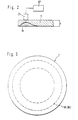
- the object of the invention is that the depth of the erosion trenches formed by this sputtering (see Fig.) Within the target is detected by means of at least one sensor.
- one or more sensors are provided on the back of the target.
- the sensor interacts with an evaluation unit that detects the depressions in the target and, after reaching a definable critical depth, triggers an optical or acoustic signal or automatically interrupts the work process.
- the senor is designed as an ultrasonic sensor and measures the thickness of the target at a position of greatest target erosion continuously or at definable time intervals.
- the ultrasonic sensor is coupled directly to the target via an ultrasonic conductor integrated in the target holding pot (cathode body).
- the evaluation unit can be controlled via an electrical circuit which interacts with at least one ultrasonic sensor and thus detects the thickness of the target. In this way, the wear of the target can be detected perfectly during the individual work breaks or during an ongoing work process, and it can thus be ensured that a substrate is coated only as long as the target has sufficient strength.
- 1 denotes a sputtering cathode, the supporting part of which consists of a hollow, pot-like base body 2 (target holding pot), which, because of the thermal load, consists of a good heat-conducting material, for example of copper, and by means of a circumferential flange 3 with the interposition of one Insulating body 4 can be inserted into a wall 5 of a housing or a vacuum chamber shown only partially in the drawing.
- a sputtering cathode the supporting part of which consists of a hollow, pot-like base body 2 (target holding pot), which, because of the thermal load, consists of a good heat-conducting material, for example of copper, and by means of a circumferential flange 3 with the interposition of one Insulating body 4 can be inserted into a wall 5 of a housing or a vacuum chamber shown only partially in the drawing.
- the sputtering cathode 1 is connected to an electrical power supply.
- a vacuum pump not shown in the drawing, is connected to the vacuum chamber.
- the basic body 2 has a largely flat end plate 6. On the inside of the end plate 6, three concentrically arranged cooling water channels 7, 8, 9 are provided, which are connected via a water connection piece 35 to a pump, not shown in the drawing.
- a target 11 is soldered to the underside of the end plate 6 and can also be connected to the end plate 6 by means of screw bolts.
- the magnet units 14, 15 which are arranged concentrically with respect to the central axis A.
- the magnet units 14, 15 consist of a permanent magnetic material and are magnetized in the axial direction.
- the middle magnet unit 14 is cylindrical Disc formed.
- the outer magnet units 15, which are likewise arranged concentrically to the central axis, are advantageously composed of numerous plate-shaped permanent magnets.
- the poles of the magnet units 14, 15 facing away from the target 11 are connected via a magnet yoke 17 made of soft magnetic material (FIG. 1).
- the magnet units 14, 15 are alternately poled, namely the pole faces facing the target 11 form a north pole in the magnet unit 14 and a south pole in the magnet unit 15. This leads to the formation of a magnetic tunnel, which is closed on the target side around the axis A-A.
- An ultrasonic sensor 28 is mounted in the target holding pot above the target 11 such that the ultrasound which is emitted and then reflected on the target surface can be conducted well via an ultrasonic conductor 29 without internal interfaces. It is of course also possible to place this sensor 28 or several sensors at different positions. It may be necessary to construct the ultrasonic sensor in an electrically insulated manner from the base body 2 and from the yoke plate.
- the target 11 Opposite the target 11 is a substrate holder, not shown in the drawing, with a substrate to be coated. If a voltage is applied to the cathode 1 after a gas, for example argon, has been introduced into the vacuum chamber, the electrons present in the vacuum chamber ionize the argon and, under suitable pressure conditions, a so-called independent gas discharge in the form of a plasma is formed. Due to the magnetic tunnel already mentioned, this plasma has the shape of an annular plasma tube and is identified by 30 in FIG.
- a gas for example argon
- the argon ions in the plasma are accelerated in a straight line by the electric field between the plasma and the target in the direction of the target 11 and, due to their high energy, knock out atoms or atomic clusters from the target material, which are then deposited on the substrate. In this way, the desired layer is formed after a certain time and the target is removed. Ring-shaped depressions 18 thus form at the point where most ions strike.
- the ring 18 shown in FIG. 3 indicates these depressions, which has approximately the same diameter as the ring of the plasma 30 formed below the target 11. It follows from this that the target 11 becomes thinner and thinner at this point.
- the ultrasound sensor 28 which is essential for the present invention, measures the thickness of the target 11 in the region of this erosion trench 18 continuously or at very specific time intervals. Precise statements about the degree of target erosion can be made in a simple manner from the individual measurement data, and thus an optimal one Use of the target can be achieved.
- the critical target strength can be measured with an accuracy of approximately 0.1 mm during the sputtering process or between individual coatings. This enables an optimal end point determination in the sense mentioned above.
- the measured target thickness is continuously or at certain time intervals, e.g. via a display, whereby when a critical thickness is reached an optical or acoustic signal is transmitted or the process is ended automatically.
Landscapes
- Physics & Mathematics (AREA)
- Engineering & Computer Science (AREA)
- Plasma & Fusion (AREA)
- Chemical & Material Sciences (AREA)
- Analytical Chemistry (AREA)
- Physical Vapour Deposition (AREA)
Applications Claiming Priority (2)
| Application Number | Priority Date | Filing Date | Title |
|---|---|---|---|
| DE4022461 | 1990-07-14 | ||
| DE19904022461 DE4022461A1 (de) | 1990-07-14 | 1990-07-14 | Zerstaeubungskathode |
Publications (1)
| Publication Number | Publication Date |
|---|---|
| EP0467012A1 true EP0467012A1 (fr) | 1992-01-22 |
Family
ID=6410295
Family Applications (1)
| Application Number | Title | Priority Date | Filing Date |
|---|---|---|---|
| EP91102613A Withdrawn EP0467012A1 (fr) | 1990-07-14 | 1991-02-22 | Cathode pour pulvérisation |
Country Status (3)
| Country | Link |
|---|---|
| EP (1) | EP0467012A1 (fr) |
| JP (1) | JPH0657421A (fr) |
| DE (1) | DE4022461A1 (fr) |
Cited By (3)
| Publication number | Priority date | Publication date | Assignee | Title |
|---|---|---|---|---|
| GB2330591A (en) * | 1997-10-24 | 1999-04-28 | Leybold Ag | Sputtering cathode containing an elastomeric foil |
| US6264804B1 (en) | 2000-04-12 | 2001-07-24 | Ske Technology Corp. | System and method for handling and masking a substrate in a sputter deposition system |
| WO2015022166A1 (fr) * | 2013-08-16 | 2015-02-19 | Heraeus Materials Technology Gmbh & Co. Kg | Cible de pulvérisation, dispositif de fixation d'une cible de pulvérisation, dispositif permettant d'identifier un détachement d'un matériau de pulvérisation, et procédé de fabrication |
Families Citing this family (3)
| Publication number | Priority date | Publication date | Assignee | Title |
|---|---|---|---|---|
| DE19617057C2 (de) | 1996-04-29 | 1998-07-23 | Ardenne Anlagentech Gmbh | Sputteranlage mit zwei längserstreckten Magnetrons |
| WO2004094688A1 (fr) * | 2003-04-02 | 2004-11-04 | Honeywell International Inc. | Constructions de plaques cible/support pvd, et procede de formation de constructions de plaques cible/support pvd |
| US7566384B2 (en) * | 2005-07-22 | 2009-07-28 | Praxair Technology, Inc. | System and apparatus for real-time monitoring and control of sputter target erosion |
Citations (4)
| Publication number | Priority date | Publication date | Assignee | Title |
|---|---|---|---|---|
| US4437332A (en) * | 1982-09-30 | 1984-03-20 | Krautkramer-Branson, Inc. | Ultrasonic thickness measuring instrument |
| EP0259934A1 (fr) * | 1986-09-10 | 1988-03-16 | Philips and Du Pont Optical Deutschland GmbH | Installation de pulvérisation cathodique ayant un dispositif de mesure de la cavitation critique de la cible |
| GB2199340A (en) * | 1986-12-23 | 1988-07-06 | Balzers Hochvakuum | Detecting erosion of the target surface of sputtering source during cathodic sputtering |
| EP0316523A2 (fr) * | 1987-11-16 | 1989-05-24 | Leybold Aktiengesellschaft | Cathode pour pulvérisation selon le principe magnétron |
Family Cites Families (8)
| Publication number | Priority date | Publication date | Assignee | Title |
|---|---|---|---|---|
| US3147169A (en) * | 1961-02-23 | 1964-09-01 | Grumman Aircraft Engineering C | Apparatus for determining thickness during chemical milling |
| EP0046154B1 (fr) * | 1980-08-08 | 1984-11-28 | Battelle Development Corporation | Appareil pour le revêtement de substrats par pulvérisation cathodique à grande vitesse, ainsi que cathode de pulvérisation pour un tel appareil |
| US4407708A (en) * | 1981-08-06 | 1983-10-04 | Eaton Corporation | Method for operating a magnetron sputtering apparatus |
| NL183317C (nl) * | 1982-06-03 | 1988-09-16 | Hoogovens Groep Bv | Hoogovenwand. |
| DD216258A1 (de) * | 1983-06-29 | 1984-12-05 | Elektronische Bauelemente Veb | verfahren und anordnung zum steuern des katodenzerstaeubungsprozesses |
| FR2551861B1 (fr) * | 1983-09-09 | 1985-10-18 | Thomson Csf | Procede de mesure de la profondeur d'une gravure ionique |
| US4872345A (en) * | 1988-03-30 | 1989-10-10 | Shell Oil Company | Measuring wall erosion |
| DE3812379A1 (de) * | 1988-04-14 | 1989-10-26 | Leybold Ag | Zerstaeubungskathode nach dem magnetron-prinzip |
-
1990
- 1990-07-14 DE DE19904022461 patent/DE4022461A1/de not_active Ceased
-
1991
- 1991-02-22 EP EP91102613A patent/EP0467012A1/fr not_active Withdrawn
- 1991-04-17 JP JP11232691A patent/JPH0657421A/ja active Pending
Patent Citations (4)
| Publication number | Priority date | Publication date | Assignee | Title |
|---|---|---|---|---|
| US4437332A (en) * | 1982-09-30 | 1984-03-20 | Krautkramer-Branson, Inc. | Ultrasonic thickness measuring instrument |
| EP0259934A1 (fr) * | 1986-09-10 | 1988-03-16 | Philips and Du Pont Optical Deutschland GmbH | Installation de pulvérisation cathodique ayant un dispositif de mesure de la cavitation critique de la cible |
| GB2199340A (en) * | 1986-12-23 | 1988-07-06 | Balzers Hochvakuum | Detecting erosion of the target surface of sputtering source during cathodic sputtering |
| EP0316523A2 (fr) * | 1987-11-16 | 1989-05-24 | Leybold Aktiengesellschaft | Cathode pour pulvérisation selon le principe magnétron |
Cited By (4)
| Publication number | Priority date | Publication date | Assignee | Title |
|---|---|---|---|---|
| GB2330591A (en) * | 1997-10-24 | 1999-04-28 | Leybold Ag | Sputtering cathode containing an elastomeric foil |
| US6264804B1 (en) | 2000-04-12 | 2001-07-24 | Ske Technology Corp. | System and method for handling and masking a substrate in a sputter deposition system |
| US6406598B2 (en) | 2000-04-12 | 2002-06-18 | Steag Hamatech Ag | System and method for transporting and sputter coating a substrate in a sputter deposition system |
| WO2015022166A1 (fr) * | 2013-08-16 | 2015-02-19 | Heraeus Materials Technology Gmbh & Co. Kg | Cible de pulvérisation, dispositif de fixation d'une cible de pulvérisation, dispositif permettant d'identifier un détachement d'un matériau de pulvérisation, et procédé de fabrication |
Also Published As
| Publication number | Publication date |
|---|---|
| JPH0657421A (ja) | 1994-03-01 |
| DE4022461A1 (de) | 1992-01-23 |
Similar Documents
| Publication | Publication Date | Title |
|---|---|---|
| DE3724937C2 (fr) | ||
| DE4106770C2 (de) | Verrichtung zum reaktiven Beschichten eines Substrats | |
| DE2824289C2 (de) | Target für Sprüh-Beschichtungsgeräte | |
| EP0812368A1 (fr) | Procede de pulverisation reactive | |
| US3652443A (en) | Deposition apparatus | |
| DE112018006577B4 (de) | Ionenfräsvorrichtung und Ionenquellen-Justierverfahren für Ionenfräsvorrichtung | |
| EP0459137A2 (fr) | Dispositif pour revêtement de substrats | |
| DE69828699T2 (de) | Vacuumzerstäubungsgerät | |
| DE4042289A1 (de) | Verfahren und vorrichtung zum reaktiven beschichten eines substrats | |
| DE4420951C2 (de) | Einrichtung zum Erfassen von Mikroüberschlägen in Zerstäubungsanlagen | |
| DE4202349C2 (de) | Vorrichtung zur Kathodenzerstäubung | |
| EP0467012A1 (fr) | Cathode pour pulvérisation | |
| EP0447764A2 (fr) | Dispositif pour le revêtement de substrats par pulvérisation cathodique | |
| DE3630737C1 (de) | Kathodenzerstaeubungseinrichtung mit einer Vorrichtung zur Messung eines kritischen Target-Abtrages | |
| DE69111490T2 (de) | Verfahren zur Vorbereitung einer Blende zur Verminderung von Teilchen in einer Kammer zur physikalischen Aufdampfung. | |
| EP0549854B1 (fr) | Cathode de revêtement d'un substrat | |
| DE3738845A1 (de) | Zerstaeubungskatode nach dem magnetronprinzip | |
| DE4345403C2 (de) | Vorrichtung zur Kathodenzerstäubung | |
| BE1029870B1 (de) | Magnetsystem, Sputtervorrichtung und Gehäusedeckel | |
| DE3442208C2 (fr) | ||
| WO1990010947A1 (fr) | Procede de detection d'une profondeur d'erosion d'un corps-cible et corps-cible utilise dans ce procede | |
| DE19819933A1 (de) | Target für eine Kathodenzerstäubungsvorrichtung zur Herstellung dünner Schichten | |
| DE4100291C1 (fr) | ||
| DE4030900A1 (de) | Verfahren und einrichtung zum beschichten von teilen | |
| EP0608478A2 (fr) | Dispositif de pulvérisation cathodique |
Legal Events
| Date | Code | Title | Description |
|---|---|---|---|
| PUAI | Public reference made under article 153(3) epc to a published international application that has entered the european phase |
Free format text: ORIGINAL CODE: 0009012 |
|
| AK | Designated contracting states |
Kind code of ref document: A1 Designated state(s): CH DE FR GB LI NL |
|
| STAA | Information on the status of an ep patent application or granted ep patent |
Free format text: STATUS: THE APPLICATION IS DEEMED TO BE WITHDRAWN |
|
| 18D | Application deemed to be withdrawn |
Effective date: 19920723 |