EP0259934A1 - Installation de pulvérisation cathodique ayant un dispositif de mesure de la cavitation critique de la cible - Google Patents
Installation de pulvérisation cathodique ayant un dispositif de mesure de la cavitation critique de la cible Download PDFInfo
- Publication number
- EP0259934A1 EP0259934A1 EP87201720A EP87201720A EP0259934A1 EP 0259934 A1 EP0259934 A1 EP 0259934A1 EP 87201720 A EP87201720 A EP 87201720A EP 87201720 A EP87201720 A EP 87201720A EP 0259934 A1 EP0259934 A1 EP 0259934A1
- Authority
- EP
- European Patent Office
- Prior art keywords
- target
- cathode
- probe
- sputtering device
- gas
- Prior art date
- Legal status (The legal status is an assumption and is not a legal conclusion. Google has not performed a legal analysis and makes no representation as to the accuracy of the status listed.)
- Granted
Links
- 238000004544 sputter deposition Methods 0.000 title claims abstract description 29
- 238000005259 measurement Methods 0.000 title description 7
- 239000000523 sample Substances 0.000 claims abstract description 58
- 239000011248 coating agent Substances 0.000 claims abstract description 8
- 238000000576 coating method Methods 0.000 claims abstract description 8
- 239000013077 target material Substances 0.000 claims abstract description 6
- 239000012141 concentrate Substances 0.000 claims abstract description 3
- 229910052751 metal Inorganic materials 0.000 claims description 16
- 239000002184 metal Substances 0.000 claims description 16
- 239000000919 ceramic Substances 0.000 claims description 8
- 229910052756 noble gas Inorganic materials 0.000 claims description 3
- RYGMFSIKBFXOCR-UHFFFAOYSA-N Copper Chemical compound [Cu] RYGMFSIKBFXOCR-UHFFFAOYSA-N 0.000 claims description 2
- 229910052782 aluminium Inorganic materials 0.000 claims description 2
- XAGFODPZIPBFFR-UHFFFAOYSA-N aluminium Chemical compound [Al] XAGFODPZIPBFFR-UHFFFAOYSA-N 0.000 claims description 2
- 229910052802 copper Inorganic materials 0.000 claims description 2
- 239000010949 copper Substances 0.000 claims description 2
- 239000007789 gas Substances 0.000 description 19
- 239000000463 material Substances 0.000 description 14
- 238000011156 evaluation Methods 0.000 description 12
- 238000000034 method Methods 0.000 description 4
- 238000001816 cooling Methods 0.000 description 2
- 239000000110 cooling liquid Substances 0.000 description 2
- 230000000694 effects Effects 0.000 description 2
- 239000011261 inert gas Substances 0.000 description 2
- 150000002500 ions Chemical class 0.000 description 2
- 239000002923 metal particle Substances 0.000 description 2
- 238000004157 plasmatron Methods 0.000 description 2
- 239000000853 adhesive Substances 0.000 description 1
- 230000001070 adhesive effect Effects 0.000 description 1
- 230000001419 dependent effect Effects 0.000 description 1
- 238000005553 drilling Methods 0.000 description 1
- 239000000155 melt Substances 0.000 description 1
- 150000002739 metals Chemical class 0.000 description 1
Images

Classifications
-
- H—ELECTRICITY
- H01—ELECTRIC ELEMENTS
- H01J—ELECTRIC DISCHARGE TUBES OR DISCHARGE LAMPS
- H01J37/00—Discharge tubes with provision for introducing objects or material to be exposed to the discharge, e.g. for the purpose of examination or processing thereof
- H01J37/32—Gas-filled discharge tubes
- H01J37/32917—Plasma diagnostics
- H01J37/32935—Monitoring and controlling tubes by information coming from the object and/or discharge
-
- C—CHEMISTRY; METALLURGY
- C23—COATING METALLIC MATERIAL; COATING MATERIAL WITH METALLIC MATERIAL; CHEMICAL SURFACE TREATMENT; DIFFUSION TREATMENT OF METALLIC MATERIAL; COATING BY VACUUM EVAPORATION, BY SPUTTERING, BY ION IMPLANTATION OR BY CHEMICAL VAPOUR DEPOSITION, IN GENERAL; INHIBITING CORROSION OF METALLIC MATERIAL OR INCRUSTATION IN GENERAL
- C23C—COATING METALLIC MATERIAL; COATING MATERIAL WITH METALLIC MATERIAL; SURFACE TREATMENT OF METALLIC MATERIAL BY DIFFUSION INTO THE SURFACE, BY CHEMICAL CONVERSION OR SUBSTITUTION; COATING BY VACUUM EVAPORATION, BY SPUTTERING, BY ION IMPLANTATION OR BY CHEMICAL VAPOUR DEPOSITION, IN GENERAL
- C23C14/00—Coating by vacuum evaporation, by sputtering or by ion implantation of the coating forming material
- C23C14/22—Coating by vacuum evaporation, by sputtering or by ion implantation of the coating forming material characterised by the process of coating
- C23C14/34—Sputtering
- C23C14/3407—Cathode assembly for sputtering apparatus, e.g. Target
Definitions
- the invention relates to a cathode sputtering device for coating the surfaces of objects, in which a vacuum chamber is provided, which contains a noble gas, and in which a target cathode and an anode are arranged, to which a voltage is applied in order to generate plasma discharges is, a magnetic field, which intensifies the plasma discharges and concentrates on the area of the target cathode, and a device for measuring the target removal are provided.
- the material of the target cathode is removed and, among other things, is deposited on the surfaces of the objects to be coated. For this reason, it is desirable to measure the removal of the target cathode or to receive an alarm signal before it is completely removed. A complete removal of the target cathode is not desirable, since in this case the back plate or parts of the cathode sputtering device are sputtered and damaged.
- a magnetron sputter coating source is known from DE-OS 34 25 344, in which the magnetic field is scanned by means of a Hall probe provided in the vicinity of the target cathode. The change in the magnetic field allows conclusions to be drawn about the target removal.
- DD-PS 220 618 a circuit arrangement for target wear determination in sputter systems is known, in which a DC voltage measurement variable is used, which is dependent on the power consumed by the plasmatron. In this way, conclusions can be drawn about the removal of the target cathode from the power consumed by the plasmatron.
- all these methods have in common that they only allow indirect measurement and thus no precise measurement of the removal of the Can deliver target cathode. In addition, these methods provide, so to speak, only a statistical mean of the removal and thus do not allow any conclusions to be drawn as to whether the material has possibly already been completely or almost completely removed.
- At least one probe is provided for measuring a critical target removal in the target cathode, which probe responds to target material that has been removed down to the probe.
- a probe is introduced into the target cathode, for example in a bore or groove, which signals that the target material surrounding it has been completely removed on at least one side.
- the probe is positioned in the target cathode in such a way that it will respond before the material is completely removed.
- the probe will therefore generally be attached in the area of the rear wall of the target cathode. If the probe is attached to a location that is preferably exposed to removal, an alarm signal can be obtained in this way with simple means before the target cathode has been completely removed at any location, indicating that the target cathode is short stands before their complete removal. This is of particular importance since any downtime of a cathode sputtering device is uneconomical.
- the device according to the invention thus offers the possibility of avoiding unnecessary downtimes. At the same time, the risk of complete removal of the target cathode has been eliminated, which is particularly important when the requirements for the purity of the coating of the surfaces to be coated are high.
- the probe contains a gas under pressure, the pressure drop of which marks the critical target removal.
- the probe for marking the critical target removal can consist, for example, of a tube which contains a gas under pressure. The pressure of this gas is registered. A pressure drop in the gas immediately signals that the probe has become leaky due to the removal of the surrounding material of the target cathode and the associated leakage.
- a chamber is provided in the probe, which is connected to a pressure switch via a pressure-tight hose connection, and that the chamber and the hose are filled with a gas, so that the pressure switch when the pressure drops Gases in response to reaching the critical target removal.
- the measurement of the pressure of the gas in the probe can be carried out in this way with the simplest of means. If the pressure switch responds, an alarm signal can be given; however, the cathode sputtering device can also be switched off immediately.
- a bore is provided in the target cathode, which is connected to a pressure switch via a pressure-tight hose connection, and that the bore and the hose are filled with a gas under pressure, so that the pressure switch in the event of a pressure drop in the gas as a result of reaching the critical target removal.
- the probe can consist of a simple hole in the target cathode, which is connected to a pressure switch via a pressure-tight hose connection. If the material of the target cathode surrounding the bore is removed at one point, the gas escapes and the pressure switch responds. In this way, a reliable measurement of a critical target removal is still possible with the simplest design effort.
- the probe has an electrically conductive measuring line, the contact of which with the discharge plasma is electronically evaluated.
- the possibility of measuring the pressure of a gas provided in the probe there is also the possibility of providing an electrically conductive measuring line in the probe, the contact of which with the discharge plasma is electronically evaluated as a result of reaching the critical target removal.
- the electrical potential of the measuring line can be evaluated in the following manner.
- the critical target removal that is to say when the target material has been removed down to the probe, the discharge plasma flows into the measuring probe and also surrounds the measuring line.
- the ions in the plasma are positively charged and influence the electrical potential of the measuring line accordingly. This change in the potential of the measuring line is recognized by the evaluation electronics, which then give a corresponding signal.
- a further embodiment of the invention provides that the measuring line runs in a ceramic tube, which is in turn encased in a metal tube, and that both tubes are open to one side in a partial area, so that the measuring line in this area leads to the target to be removed. Material is exposed.
- the measuring line has proven to be advantageous to arrange the measuring line in a ceramic tube, since this has an electrically insulating effect.
- the ceramic tube is in turn surrounded by a metal tube. Both tubes are open in a partial area to the side of the target cathode to be removed. If the material of the target cathode is removed up to this area, the measuring line comes into electrical contact with the discharge plasma, which, as described above, can be evaluated electronically.
- the probe is arranged in the area of the target electrode which is removed the fastest.
- the most rapidly removed area of the target electrode is known empirically. In these cases there is no problem in providing one or more probes in these areas.
- the magnetic field of the sputtering device is stronger in a defined area of the target cathode than in the other areas and that the probe is arranged in this defined area.
- the target cathode consisting of the metal to be removed is provided with a back plate made of another metal and that the probe is arranged in the metal to be removed in a border region to the back plate.
- the target cathode made of the material to be removed has a back plate, which is also made of a metal.
- a back plate which is also made of a metal.
- a cathode sputtering device shown in section in FIG. 1 for coating the surfaces of objects has a vacuum chamber 1 in which a target cathode 2 and an anode 3 are arranged.
- the vacuum chamber 1 is completely airtight and can be evacuated from air by means of a pump 5 connected to an opening 4.
- Noble gas is supplied to the chamber 1 from the outside via a second opening 6 via a metering valve 7.
- the chamber has two openings 1a and 1b which lead to the outside and are introduced into the chamber through the objects which are not shown in the figure, and through which the objects are brought out again after coating.
- the openings 1a and 1b open into tubular extensions which, like the chamber 1 itself, are also airtight in the manner not shown in the figure.
- the anode 3 extends in a ring shape in the vacuum chamber 1, while the cathode 2 extends in an upper region of the chamber 1 provided electrically conductive holder 11 is arranged inside the chamber.
- the target cathode 2 is connected to the holder 11 via a rear plate 12.
- Two arrangements 13 and 14 for generating a magnetic field are provided in the holder 11 above the back plate 12 of the target cathode 2.
- the magnetic fields point with their north or south poles to the back plate 12 and extend approximately parallel to the target cathode in partial areas thereof.
- cooling channels 15 are provided in the holder, through which a cooling liquid flows. The cooling liquid is fed to the channels via a pipe 16 and discharged through a pipe 17.
- the tubes 16 and 17 are led out of the chamber 1 through seals 18 and 19.
- At least the seal 18 is designed so that it has an electrically insulating effect between the tube 18 and the wall of the chamber 1.
- at least the tube 18, if desired also the tube 19, is made electrically conductive.
- the cathode 2 is connected to a negative pole 21 of a voltage source 22 via the back plate 12 and the tube 18, which is electrically conductively connected to the back plate 12 via at least one of the cooling channels 15.
- a positive pole 23 of the voltage source 22 is connected to ground.
- the anode 3 arranged in the chamber 1 is also connected to ground.
- the voltage source 22 can be controlled by an evaluation unit 30, which receives measurement signals from a probe in a manner not shown in the figure. The detailed functional description of the evaluation electronics 30 and the probe, not shown in the figure, will be made with reference to FIGS. 3 to 5.
- the function of the cathode sputtering device shown in FIG. 1 is as follows:
- a voltage which is positive with respect to the anode 3 is applied to the target cathode 2 by means of the voltage source 22.
- the target cathode and the anode are located in the vacuum chamber 1 filled with an inert gas.
- plasma discharges of the inert gas take place between these two electrodes. These plasma discharges are concentrated on the area of the target cathode by means of the magnet arrangements 13 and 14.
- the positive ions of the gas thereby increasingly hit the surface of the target cathode 2 and detach particles of the metal from which it is made. These metal particles are deposited on a surface 35 of a planar object 36 shown in section in FIG. 1.
- the surface 35 of the object 36 is coated with a thin layer, which consists of the material of the target cathode 2.
- the parameters for setting the intensity of the plasma discharges are the gas pressure, the voltage applied between the electrodes and, if appropriate, the strength of the magnetic field.
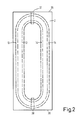
- FIG. 2 shows the target electrode 2 according to FIG. 1 in a top view from the anode side.
- the target cathode 2 has an approximately rectangular shape.
- the magnetic field arrangements 13 and 14 are also shown schematically in the top view of FIG. 2. These magnetic field arrangements run in the form of an oval. In the example shown in FIG. 2, the magnetic field arrangements run in the head regions 35 and 36 of the target cathode in a relatively small radius, so that a relatively strong magnetic field is formed in these regions. For this reason, the material of the target cathode is removed relatively strongly in these areas. It therefore makes sense to arrange a probe for measuring a critical target removal in one or both of these areas. In the figure, two possible locations 37 and 38 of such probes are shown schematically.
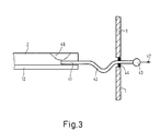
- a probe for measuring a critical target removal together with a target cathode is shown in section as a first embodiment.
- the target cathode 2 which can be of the type shown in FIGS. 1 and 2, for example, has a back plate 12 on its rear side.
- the target cathode itself can be made of aluminum, for example, and the back plate of copper, for example.
- a bore 41 is made in the target cathode 2 shown in FIG. 3 in an area near the rear wall 12. This bore is connected to a pressure sensor 43 via a flexible, but gas-tight and electrically insulating hose 42 the.
- the hose 42 is guided through a seal 44.
- the seal 44 is in turn connected in a wall of the chamber of a sputtering device, which can be, for example, the chamber 1 shown in FIG. 1.
- a sputtering device which can be, for example, the chamber 1 shown in FIG. 1.
- Both the bore 41 in the target cathode and the tube 42 are filled with a gas. This gas pressure is measured by the pressure sensor 43.
- a possible removal 46 is entered in the figure as an example in the target cathode 2. When this removal 46 reaches the bore 41, the gas under pressure in the bore 41 and the hose 42 escapes through this opening. As a result, the pressure in the system drops, which is reported by the pressure sensor 43. This can be done, for example, in such a way that the pressure sensor 43 sends an electrical signal to an evaluation electronics 30, shown schematically in FIG. 1, which in turn interrupts the voltage applied to the electrodes 3 and 2.
- a probe can also be inserted into such a bore, which in turn is connected to the pressure sensor via a hose and which has a chamber which is filled with a gas.
- the probe must then consist of the same material as the target cathode.
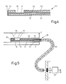
- FIG. 4 shows a second embodiment of a probe for measuring a critical target removal in section.
- This embodiment is an electrically working probe 50.
- a measuring line 51 is arranged inside the probe 50.
- the measuring line 51 is surrounded by a ceramic tube 52 and this in turn is surrounded by a metal tube 53.
- the first 4 At its first end 54, the first 4, the measuring line 51, the ceramic tube 52 and the metal tube 53 are closed off with an electrically insulating cover 55 into a bore or groove of a target cathode (not shown in FIG. 4).
- This cover 55 can be glued with ceramic adhesive, for example.
- the ceramic tube 52 and the metal tube 53 are open in a semi-cylindrical region 56. In the installed state, this region 56 points to the side of the target cathode which is being removed.
- FIG. 5 In which the probe shown in FIG. 4 working in an electrical manner and a target cathode, which can be, for example, the target cathode 2 shown in FIGS. 1 and 2, are shown in section .
- the probe 50 is inserted into a bore 61 of the target cathode 2.
- the bore 61 is made in an area adjacent to the back plate 12.
- a possible removal 62 is shown as an example in the target cathode 2 in FIG. 5. This removal 62 is shown in the figure shortly before the breakthrough to the probe.
- the measuring line 51 in the probe is connected via an insulated cable 63 to evaluation electronics, which can be evaluation electronics 30 shown in FIG. 1, for example.
- the cable is guided through an insulated feedthrough 64.
- This insulated feedthrough 64 is located, for example, in a wall of the vacuum chamber 1 shown in FIG. 1.
- the measuring line 51 of the probe 50 is therefore connected to the evaluation electronics 30 via the cable connection 63.
- the evaluation electronics 30 measures the electrical potential at which the measuring line 51 lies.
- the removal 62 shown schematically in the figure reaches the open area 55 reached the probe, the measuring line is in contact with the positively charged discharge plasma.
- This is registered by the evaluation electronics 30 as a result of a changing electrical potential of the measuring line 51 connected to the evaluation electronics 30 via the cable connection 63, and a corresponding signal 65 is given to the outside, which can serve, for example, to supply the voltage to the Interrupt electrodes of the sputtering device.
- the measuring line could also be a resistance wire, which changes its terminating resistance to the measuring electronics 30 as soon as it melts.
Landscapes
- Chemical & Material Sciences (AREA)
- Engineering & Computer Science (AREA)
- Chemical Kinetics & Catalysis (AREA)
- Materials Engineering (AREA)
- Mechanical Engineering (AREA)
- Metallurgy (AREA)
- Organic Chemistry (AREA)
- Physics & Mathematics (AREA)
- Plasma & Fusion (AREA)
- Analytical Chemistry (AREA)
- Physical Vapour Deposition (AREA)
- Measuring Fluid Pressure (AREA)
Applications Claiming Priority (2)
| Application Number | Priority Date | Filing Date | Title |
|---|---|---|---|
| DE3630737 | 1986-09-10 | ||
| DE3630737A DE3630737C1 (de) | 1986-09-10 | 1986-09-10 | Kathodenzerstaeubungseinrichtung mit einer Vorrichtung zur Messung eines kritischen Target-Abtrages |
Publications (2)
| Publication Number | Publication Date |
|---|---|
| EP0259934A1 true EP0259934A1 (fr) | 1988-03-16 |
| EP0259934B1 EP0259934B1 (fr) | 1992-01-02 |
Family
ID=6309251
Family Applications (1)
| Application Number | Title | Priority Date | Filing Date |
|---|---|---|---|
| EP87201720A Expired - Lifetime EP0259934B1 (fr) | 1986-09-10 | 1987-09-09 | Installation de pulvérisation cathodique ayant un dispositif de mesure de la cavitation critique de la cible |
Country Status (6)
| Country | Link |
|---|---|
| US (1) | US5380419A (fr) |
| EP (1) | EP0259934B1 (fr) |
| JP (1) | JPS63121661A (fr) |
| KR (1) | KR950001216B1 (fr) |
| DE (2) | DE3630737C1 (fr) |
| HK (1) | HK70494A (fr) |
Cited By (2)
| Publication number | Priority date | Publication date | Assignee | Title |
|---|---|---|---|---|
| EP0467012A1 (fr) * | 1990-07-14 | 1992-01-22 | Leybold Aktiengesellschaft | Cathode pour pulvérisation |
| WO2006083627A1 (fr) * | 2005-01-31 | 2006-08-10 | Advanced Plasma Inc | Detecteurs de plasma pour la detection de point terminal et de fin de vie avec detecteur d’auto-diagnostic |
Families Citing this family (11)
| Publication number | Priority date | Publication date | Assignee | Title |
|---|---|---|---|---|
| CH669609A5 (fr) * | 1986-12-23 | 1989-03-31 | Balzers Hochvakuum | |
| EP0401622B1 (fr) * | 1989-06-05 | 1995-08-23 | Balzers Aktiengesellschaft | Procédé de refroidissement de cible ainsi que dispositifs de refroidissement de cibles |
| EP0615273A1 (fr) * | 1993-03-12 | 1994-09-14 | Applied Materials, Inc. | Procédé et appareil pour détecter l'éerosion de cible de pulvérisation |
| JPH08176808A (ja) * | 1993-04-28 | 1996-07-09 | Japan Energy Corp | 寿命警報機能を備えたスパッタリングタ−ゲット |
| WO2004024979A1 (fr) * | 2002-09-12 | 2004-03-25 | Honeywell International Inc. | Systeme de detection et procedes utilises pour la detection d'usure de materiau et de deterioration de surface |
| US6811657B2 (en) * | 2003-01-27 | 2004-11-02 | Micron Technology, Inc. | Device for measuring the profile of a metal film sputter deposition target, and system and method employing same |
| US20060081459A1 (en) * | 2004-10-18 | 2006-04-20 | Applied Materials, Inc. | In-situ monitoring of target erosion |
| US8795486B2 (en) * | 2005-09-26 | 2014-08-05 | Taiwan Semiconductor Manufacturing Company, Ltd. | PVD target with end of service life detection capability |
| US7891536B2 (en) * | 2005-09-26 | 2011-02-22 | Taiwan Semiconductor Manufacturing Co., Ltd. | PVD target with end of service life detection capability |
| US20070068796A1 (en) * | 2005-09-26 | 2007-03-29 | Taiwan Semiconductor Manufacturing Co., Ltd. | Method of using a target having end of service life detection capability |
| DE102010052341B4 (de) * | 2010-11-25 | 2015-02-12 | Von Ardenne Gmbh | Schutzvorrichtung an Rohrtargets |
Citations (5)
| Publication number | Priority date | Publication date | Assignee | Title |
|---|---|---|---|---|
| EP0005641A1 (fr) * | 1978-05-24 | 1979-11-28 | Gould Inc. | Procédé et dispositif pour contrôler et régler le processus de dépôt par pulvérisation cathodique |
| US4379040A (en) * | 1981-01-29 | 1983-04-05 | Ppg Industries, Inc. | Method of and apparatus for control of reactive sputtering deposition |
| US4426264A (en) * | 1980-12-13 | 1984-01-17 | Leybold Heraeus Gmbh | Method and means for controlling sputtering apparatus |
| DD220618A1 (de) * | 1984-01-09 | 1985-04-03 | Mikroelektronik Zt Forsch Tech | Schaltungsanordnung zur targetverschleissbestimmung in sputteranlagen |
| US4545882A (en) * | 1983-09-02 | 1985-10-08 | Shatterproof Glass Corporation | Method and apparatus for detecting sputtering target depletion |
Family Cites Families (9)
| Publication number | Priority date | Publication date | Assignee | Title |
|---|---|---|---|---|
| US4324631A (en) * | 1979-07-23 | 1982-04-13 | Spin Physics, Inc. | Magnetron sputtering of magnetic materials |
| EP0046154B1 (fr) * | 1980-08-08 | 1984-11-28 | Battelle Development Corporation | Appareil pour le revêtement de substrats par pulvérisation cathodique à grande vitesse, ainsi que cathode de pulvérisation pour un tel appareil |
| US4407708A (en) * | 1981-08-06 | 1983-10-04 | Eaton Corporation | Method for operating a magnetron sputtering apparatus |
| JPS5881968A (ja) * | 1981-11-06 | 1983-05-17 | Hitachi Ltd | 成膜装置における膜厚補正制御方法 |
| CA1242989A (fr) * | 1983-07-19 | 1988-10-11 | Donald R. Boys | Appareil et methode de controle pour la pulverisation cathodique |
| NL8402012A (nl) * | 1983-07-19 | 1985-02-18 | Varian Associates | Magnetron spetter deklaag opbrengbron voor zowel magnetische als niet-magnetische trefplaatmaterialen. |
| GB2149034A (en) * | 1983-11-12 | 1985-06-05 | Hazel Grove Jig & Tool Co Limi | Brake pad wear indicator |
| CA1253779A (fr) * | 1984-06-11 | 1989-05-09 | Robert L. Dobson | Monture de surete, et sa fabrication |
| DE8419083U1 (de) * | 1984-06-26 | 1985-10-24 | Textar Gmbh, 5090 Leverkusen | Anzeigevorrichtung für Reibbeläge von Scheibenbremsen für Kraftfahrzeuge |
-
1986
- 1986-09-10 DE DE3630737A patent/DE3630737C1/de not_active Expired
-
1987
- 1987-09-09 DE DE8787201720T patent/DE3775667D1/de not_active Expired - Lifetime
- 1987-09-09 EP EP87201720A patent/EP0259934B1/fr not_active Expired - Lifetime
- 1987-09-10 KR KR1019870010025A patent/KR950001216B1/ko not_active Expired - Lifetime
- 1987-09-10 JP JP62225413A patent/JPS63121661A/ja active Pending
-
1993
- 1993-05-05 US US08/057,204 patent/US5380419A/en not_active Expired - Fee Related
-
1994
- 1994-07-21 HK HK70494A patent/HK70494A/xx unknown
Patent Citations (5)
| Publication number | Priority date | Publication date | Assignee | Title |
|---|---|---|---|---|
| EP0005641A1 (fr) * | 1978-05-24 | 1979-11-28 | Gould Inc. | Procédé et dispositif pour contrôler et régler le processus de dépôt par pulvérisation cathodique |
| US4426264A (en) * | 1980-12-13 | 1984-01-17 | Leybold Heraeus Gmbh | Method and means for controlling sputtering apparatus |
| US4379040A (en) * | 1981-01-29 | 1983-04-05 | Ppg Industries, Inc. | Method of and apparatus for control of reactive sputtering deposition |
| US4545882A (en) * | 1983-09-02 | 1985-10-08 | Shatterproof Glass Corporation | Method and apparatus for detecting sputtering target depletion |
| DD220618A1 (de) * | 1984-01-09 | 1985-04-03 | Mikroelektronik Zt Forsch Tech | Schaltungsanordnung zur targetverschleissbestimmung in sputteranlagen |
Non-Patent Citations (1)
| Title |
|---|
| PATENT ABSTRACTS OF JAPAN, unexamined applications, Feild C, Band 7, Nr. 175, 3. August 1983 THE PATENT OFFICE JAPANESE GOVERNMENT Seite 92 C 179 & JP-A-58-81 968 (hitachi seisakusho k.k.) * |
Cited By (2)
| Publication number | Priority date | Publication date | Assignee | Title |
|---|---|---|---|---|
| EP0467012A1 (fr) * | 1990-07-14 | 1992-01-22 | Leybold Aktiengesellschaft | Cathode pour pulvérisation |
| WO2006083627A1 (fr) * | 2005-01-31 | 2006-08-10 | Advanced Plasma Inc | Detecteurs de plasma pour la detection de point terminal et de fin de vie avec detecteur d’auto-diagnostic |
Also Published As
| Publication number | Publication date |
|---|---|
| KR880004130A (ko) | 1988-06-01 |
| JPS63121661A (ja) | 1988-05-25 |
| HK70494A (en) | 1994-07-29 |
| DE3630737C1 (de) | 1987-11-05 |
| DE3775667D1 (de) | 1992-02-13 |
| US5380419A (en) | 1995-01-10 |
| EP0259934B1 (fr) | 1992-01-02 |
| KR950001216B1 (ko) | 1995-02-14 |
Similar Documents
| Publication | Publication Date | Title |
|---|---|---|
| DE3724937C2 (fr) | ||
| EP0259934B1 (fr) | Installation de pulvérisation cathodique ayant un dispositif de mesure de la cavitation critique de la cible | |
| DE4106770C2 (de) | Verrichtung zum reaktiven Beschichten eines Substrats | |
| DE3211229C2 (fr) | ||
| EP0416241B1 (fr) | Dispositif pour le revêtement d'un substrat | |
| DE2556607C2 (de) | Verfahren und Vorrichtung zur Kathodenzerstäubung | |
| DE4441206A1 (de) | Einrichtung für die Unterdrückung von Überschlägen in Kathoden-Zerstäubungseinrichtungen | |
| DE4420951C2 (de) | Einrichtung zum Erfassen von Mikroüberschlägen in Zerstäubungsanlagen | |
| DE19807402A1 (de) | Massenspektrometer und Massenspektrometrieverfahren mit Plasmaionenquelle | |
| DE4042288A1 (de) | Verfahren und vorrichtung zum reaktiven beschichten eines substrats | |
| DE1515295B1 (de) | Vorrichtung zum Aufbringen dünner Schichten aus dem Material einer Zerstäubungskathode auf eine senkrecht zu einer Anode angeordnete Unterlage | |
| DE112013000459B4 (de) | Verdrahtungsverfahren | |
| EP0316523A2 (fr) | Cathode pour pulvérisation selon le principe magnétron | |
| DE4239218C2 (de) | Anordnung zum Verhindern von Überschlägen in einem Plasma-Prozeßraum | |
| DE4123589C2 (de) | Vorrichtung zum Messen der Lichtstrahlung eines Plasmas | |
| DE4136655C2 (de) | Vorrichtung zum reaktiven Beschichten eines Substrats | |
| WO1990010947A1 (fr) | Procede de detection d'une profondeur d'erosion d'un corps-cible et corps-cible utilise dans ce procede | |
| EP0254168A2 (fr) | Cathode de pulvérisation pour dispositifs de dépôt sous vide | |
| DD285463A5 (de) | Verfahren zur regelung der brennfleckpostion bei einem vakuumbogenverdampfer | |
| EP0015391B1 (fr) | Lampe à décharge luminescente pour l'analyse spectrale qualitative et quantitative | |
| DE19540434C1 (de) | Vorrichtung zur Analyse von Werkstoffproben, insbesondere von elektrisch nicht leitfähigen Proben, mittels Hochfrequenz-Glimmentladung | |
| EP0467012A1 (fr) | Cathode pour pulvérisation | |
| DE1265338B (de) | Gasentladungseinrichtung mit Penning-Entladung zur Erzeugung und Messung von Hochvakuum | |
| DE2655942C2 (fr) | ||
| WO2001080282A2 (fr) | Source de decharge luminescente pour l'analyse elementaire |
Legal Events
| Date | Code | Title | Description |
|---|---|---|---|
| PUAI | Public reference made under article 153(3) epc to a published international application that has entered the european phase |
Free format text: ORIGINAL CODE: 0009012 |
|
| AK | Designated contracting states |
Kind code of ref document: A1 Designated state(s): CH DE ES FR GB IT LI |
|
| 17P | Request for examination filed |
Effective date: 19880902 |
|
| 17Q | First examination report despatched |
Effective date: 19900206 |
|
| GRAA | (expected) grant |
Free format text: ORIGINAL CODE: 0009210 |
|
| AK | Designated contracting states |
Kind code of ref document: B1 Designated state(s): CH DE ES FR GB IT LI |
|
| PG25 | Lapsed in a contracting state [announced via postgrant information from national office to epo] |
Ref country code: IT Free format text: LAPSE BECAUSE OF FAILURE TO SUBMIT A TRANSLATION OF THE DESCRIPTION OR TO PAY THE FEE WITHIN THE PRE;WARNING: LAPSES OF ITALIAN PATENTS WITH EFFECTIVE DATE BEFORE 2007 MAY HAVE OCCURRED AT ANY TIME BEFORE 2007. THE CORRECT EFFECTIVE DATE MAY BE DIFFERENT FROM THE ONE RECORDED.SCRIBED TIME-LIMIT Effective date: 19920102 |
|
| REF | Corresponds to: |
Ref document number: 3775667 Country of ref document: DE Date of ref document: 19920213 |
|
| PG25 | Lapsed in a contracting state [announced via postgrant information from national office to epo] |
Ref country code: ES Free format text: LAPSE BECAUSE OF FAILURE TO SUBMIT A TRANSLATION OF THE DESCRIPTION OR TO PAY THE FEE WITHIN THE PRESCRIBED TIME-LIMIT Effective date: 19920413 |
|
| GBT | Gb: translation of ep patent filed (gb section 77(6)(a)/1977) | ||
| ET | Fr: translation filed | ||
| PG25 | Lapsed in a contracting state [announced via postgrant information from national office to epo] |
Ref country code: LI Effective date: 19920930 Ref country code: CH Effective date: 19920930 |
|
| PLBE | No opposition filed within time limit |
Free format text: ORIGINAL CODE: 0009261 |
|
| STAA | Information on the status of an ep patent application or granted ep patent |
Free format text: STATUS: NO OPPOSITION FILED WITHIN TIME LIMIT |
|
| 26N | No opposition filed | ||
| REG | Reference to a national code |
Ref country code: CH Ref legal event code: AUV Free format text: DAS OBENGENANNTE PATENT IST, MANGELS BEZAHLUNG DER 6. JAHRESGEBUEHR, GELOESCHT WORDEN. Ref country code: CH Ref legal event code: PL |
|
| REG | Reference to a national code |
Ref country code: GB Ref legal event code: 732E |
|
| PGFP | Annual fee paid to national office [announced via postgrant information from national office to epo] |
Ref country code: GB Payment date: 19940901 Year of fee payment: 8 |
|
| PGFP | Annual fee paid to national office [announced via postgrant information from national office to epo] |
Ref country code: FR Payment date: 19940928 Year of fee payment: 8 |
|
| PG25 | Lapsed in a contracting state [announced via postgrant information from national office to epo] |
Ref country code: GB Effective date: 19950909 |
|
| PGFP | Annual fee paid to national office [announced via postgrant information from national office to epo] |
Ref country code: DE Payment date: 19951123 Year of fee payment: 9 |
|
| GBPC | Gb: european patent ceased through non-payment of renewal fee |
Effective date: 19950909 |
|
| PG25 | Lapsed in a contracting state [announced via postgrant information from national office to epo] |
Ref country code: FR Effective date: 19960531 |
|
| REG | Reference to a national code |
Ref country code: FR Ref legal event code: ST |
|
| PG25 | Lapsed in a contracting state [announced via postgrant information from national office to epo] |
Ref country code: DE Effective date: 19970603 |