EP0467038B1 - Alimentation de broche avec effet de succion - Google Patents
Alimentation de broche avec effet de succion Download PDFInfo
- Publication number
- EP0467038B1 EP0467038B1 EP91108036A EP91108036A EP0467038B1 EP 0467038 B1 EP0467038 B1 EP 0467038B1 EP 91108036 A EP91108036 A EP 91108036A EP 91108036 A EP91108036 A EP 91108036A EP 0467038 B1 EP0467038 B1 EP 0467038B1
- Authority
- EP
- European Patent Office
- Prior art keywords
- spindle
- supply member
- spindle head
- gap
- accordance
- Prior art date
- Legal status (The legal status is an assumption and is not a legal conclusion. Google has not performed a legal analysis and makes no representation as to the accuracy of the status listed.)
- Expired - Lifetime
Links
- 230000000694 effects Effects 0.000 title abstract description 9
- 239000000314 lubricant Substances 0.000 claims abstract description 13
- 239000002826 coolant Substances 0.000 claims abstract description 12
- 230000007704 transition Effects 0.000 claims description 10
- 230000004323 axial length Effects 0.000 claims 1
- 238000007789 sealing Methods 0.000 abstract description 3
- XLYOFNOQVPJJNP-UHFFFAOYSA-N water Substances O XLYOFNOQVPJJNP-UHFFFAOYSA-N 0.000 abstract description 3
- 238000005553 drilling Methods 0.000 abstract description 2
- 230000013011 mating Effects 0.000 abstract 1
- 238000001816 cooling Methods 0.000 description 1
Images
Classifications
-
- B—PERFORMING OPERATIONS; TRANSPORTING
- B23—MACHINE TOOLS; METAL-WORKING NOT OTHERWISE PROVIDED FOR
- B23Q—DETAILS, COMPONENTS, OR ACCESSORIES FOR MACHINE TOOLS, e.g. ARRANGEMENTS FOR COPYING OR CONTROLLING; MACHINE TOOLS IN GENERAL CHARACTERISED BY THE CONSTRUCTION OF PARTICULAR DETAILS OR COMPONENTS; COMBINATIONS OR ASSOCIATIONS OF METAL-WORKING MACHINES, NOT DIRECTED TO A PARTICULAR RESULT
- B23Q1/00—Members which are comprised in the general build-up of a form of machine, particularly relatively large fixed members
- B23Q1/0009—Energy-transferring means or control lines for movable machine parts; Control panels or boxes; Control parts
- B23Q1/0018—Energy-transferring means or control lines for movable machine parts; Control panels or boxes; Control parts comprising hydraulic means
-
- F—MECHANICAL ENGINEERING; LIGHTING; HEATING; WEAPONS; BLASTING
- F16—ENGINEERING ELEMENTS AND UNITS; GENERAL MEASURES FOR PRODUCING AND MAINTAINING EFFECTIVE FUNCTIONING OF MACHINES OR INSTALLATIONS; THERMAL INSULATION IN GENERAL
- F16L—PIPES; JOINTS OR FITTINGS FOR PIPES; SUPPORTS FOR PIPES, CABLES OR PROTECTIVE TUBING; MEANS FOR THERMAL INSULATION IN GENERAL
- F16L27/00—Adjustable joints; Joints allowing movement
- F16L27/08—Adjustable joints; Joints allowing movement allowing adjustment or movement only about the axis of one pipe
- F16L27/0804—Adjustable joints; Joints allowing movement allowing adjustment or movement only about the axis of one pipe the fluid passing axially from one joint element to another
- F16L27/0808—Adjustable joints; Joints allowing movement allowing adjustment or movement only about the axis of one pipe the fluid passing axially from one joint element to another the joint elements extending coaxially for some distance from their point of separation
- F16L27/0824—Adjustable joints; Joints allowing movement allowing adjustment or movement only about the axis of one pipe the fluid passing axially from one joint element to another the joint elements extending coaxially for some distance from their point of separation with ball or roller bearings
- F16L27/0828—Adjustable joints; Joints allowing movement allowing adjustment or movement only about the axis of one pipe the fluid passing axially from one joint element to another the joint elements extending coaxially for some distance from their point of separation with ball or roller bearings having radial bearings
Definitions
- the invention relates to a spindle head with an arrangement for supplying the respective drilling and / or cutting tools with coolant and / or lubricant Tool work area is provided, the feed member and the spindle coaxially interlocking to form a gap seal.
- a spindle head of this type is known from DE-OS 37 42 094.
- the transition of the cooling and / or lubricant from the stationary feed element to the axial channel of the spindle is sealed by means of a gap seal lying coaxially between the feed element and the spindle.
- this gap seal causes an unavoidable leak, which increases with increasing feed pressure and sets undesired limits for the desired increase in this feed pressure and prevents working with increased nominal pressures.
- the high leakage loss caused by the backflow in the gap seal has an extremely disadvantageous effect on the efficiency of the coolant and / or lubricant feed.
- the object of the invention is to design a spindle head of the type specified at the outset with a simple structure such that leaks, sealing loads and signs of wear, in particular, are minimized even when coolant and / or lubricant is supplied under high pressure.
- this object is achieved in that the free flow cross section of the feed member is smaller than the free flow cross section of the axial channel in the transition region, at least in the region of the transition into the axial channel of the spindle.
- Such a design of a spindle head causes a suction effect in the manner of a water jet pump in the region of the passage of the coolant and / or lubricant from the feed element to the axial channel of the spindle.
- This effect has the effect that a pressure drop occurs in the gap seal and a suction occurs in the gap, which counteracts the coolant and / or lubricant from entering the gap and thus minimizes leakages.
- it is also possible to work with high feed pressures since the suction effect that can be achieved occurs in a more developed manner with increasing feed pressure and therefore there is no disruptive leakage flow in the gap seal even at these high pressures.
- the opening of the feed element is preferably designed as a nozzle, which increases the water jet pump effect and increases the pressure drop in the gap. This can further reduce any leakage currents that may occur.
- nozzles for example screwable
- different types of nozzles can be attached to the feed element. In this way, an optimal coordination of the pressure required for the transport of the coolant and / or lubricant and the pressure drop to be generated in the gap can be achieved.
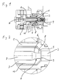
- Figure 1 shows a spindle 1 and a feed member 3, which interlock to form a coaxial gap 10.
- the spindle 1 has an axial channel 2 for transporting the coolant and / or lubricant.
- the free flow cross-section of the channel 7 provided in the feed element 3 is smaller in the region of the transition into the axial channel 2 of the spindle 1 than the free flow cross-section of the axial channel 2 of the spindle 1.
- the channel 7, which is cylindrical in the feed element 3, has a throttle point 6 on the mouth side, which in passes a cylindrical end portion 8.
- the size of the transition gap 9 between the free end of the feed member 3 and the axial channel 2 of the spindle 1 is essentially equal to the radial extent of the gap 10 of the coaxial gap seal.
- the transition gap 9 is connected via a frustoconical gap 5 to the sealing gap 10 running in the axial direction.
- the opening 4 of the feed member 3 is designed as a nozzle.
- FIG. 2 shows a detailed view of the transition area of the coolant and / or lubricant from the feed element 3 to the axial channel 2 of the spindle 1 according to FIG. 1.
Landscapes
- Engineering & Computer Science (AREA)
- General Engineering & Computer Science (AREA)
- Mechanical Engineering (AREA)
- Auxiliary Devices For Machine Tools (AREA)
- Casting Support Devices, Ladles, And Melt Control Thereby (AREA)
- Drilling And Boring (AREA)
Claims (10)
Applications Claiming Priority (2)
| Application Number | Priority Date | Filing Date | Title |
|---|---|---|---|
| DE4022895A DE4022895A1 (de) | 1990-07-18 | 1990-07-18 | Spindelkopfspeisung mit sogeffekt |
| DE4022895 | 1990-07-18 |
Publications (4)
| Publication Number | Publication Date |
|---|---|
| EP0467038A2 EP0467038A2 (fr) | 1992-01-22 |
| EP0467038A3 EP0467038A3 (en) | 1992-06-17 |
| EP0467038B1 true EP0467038B1 (fr) | 1994-08-10 |
| EP0467038B2 EP0467038B2 (fr) | 1998-07-29 |
Family
ID=6410550
Family Applications (1)
| Application Number | Title | Priority Date | Filing Date |
|---|---|---|---|
| EP91108036A Expired - Lifetime EP0467038B2 (fr) | 1990-07-18 | 1991-05-17 | Alimentation de broche avec effet de succion |
Country Status (5)
| Country | Link |
|---|---|
| EP (1) | EP0467038B2 (fr) |
| AT (1) | ATE109708T1 (fr) |
| DE (2) | DE4022895A1 (fr) |
| DK (1) | DK0467038T4 (fr) |
| ES (1) | ES2057660T5 (fr) |
Families Citing this family (1)
| Publication number | Priority date | Publication date | Assignee | Title |
|---|---|---|---|---|
| JP6892594B2 (ja) | 2017-03-14 | 2021-06-23 | スター精密株式会社 | 工作機械 |
Family Cites Families (8)
| Publication number | Priority date | Publication date | Assignee | Title |
|---|---|---|---|---|
| DE919026C (de) * | 1951-05-22 | 1954-10-11 | Friedrich Kupper | Vorrichtung zum Zufuehren des Schmiermittels in einen umlaufenden Messerkopf |
| DE1267920B (de) * | 1965-12-18 | 1968-05-09 | Buckau Wolf Maschf R | Vorrichtung zum Einfuehren eines unter Druck stehenden Mediums von einer nicht drehbaren Zuleitung in eine rotierende Hohlwelle |
| US3487748A (en) * | 1968-04-29 | 1970-01-06 | Contour Saws | Coolant applicator for rotary metal cutting tools |
| DE3007709A1 (de) * | 1980-02-29 | 1981-10-01 | Gleitlagertechnik Gmbh, 7000 Stuttgart | Einrichtung zum zufuehren von kuehlmittel bei werkzeugen |
| EP0126793B1 (fr) * | 1983-05-28 | 1986-08-27 | TBT Tiefbohrtechnik GmbH und Co. KG. | Dispositif d'aspiration d'un agent de refroidissement et/ou de graissage hors d'un trou sur une machine à percer des trous profonds |
| US4640652A (en) * | 1986-06-30 | 1987-02-03 | Scully-Jones Corp. | Coolant delivery system |
| DE3641190A1 (de) * | 1986-12-03 | 1988-07-28 | Koertner Reiner | Werkstoffbearbeitungs-vorrichtung |
| DE3742094C2 (de) * | 1987-12-11 | 1995-09-14 | Hellmerich Werkzeugmaschinen G | Mehrspindelkopf mit Kühl- und Schmiermittelvorrichtung |
-
1990
- 1990-07-18 DE DE4022895A patent/DE4022895A1/de not_active Withdrawn
-
1991
- 1991-05-17 ES ES91108036T patent/ES2057660T5/es not_active Expired - Lifetime
- 1991-05-17 DK DK91108036T patent/DK0467038T4/da active
- 1991-05-17 EP EP91108036A patent/EP0467038B2/fr not_active Expired - Lifetime
- 1991-05-17 DE DE59102479T patent/DE59102479D1/de not_active Expired - Fee Related
- 1991-05-17 AT AT91108036T patent/ATE109708T1/de not_active IP Right Cessation
Also Published As
| Publication number | Publication date |
|---|---|
| ES2057660T3 (es) | 1994-10-16 |
| ATE109708T1 (de) | 1994-08-15 |
| EP0467038B2 (fr) | 1998-07-29 |
| DE59102479D1 (de) | 1994-09-15 |
| EP0467038A2 (fr) | 1992-01-22 |
| ES2057660T5 (es) | 1998-10-16 |
| EP0467038A3 (en) | 1992-06-17 |
| DK0467038T4 (da) | 1999-02-01 |
| DE4022895A1 (de) | 1992-01-23 |
| DK0467038T3 (da) | 1994-09-26 |
Similar Documents
| Publication | Publication Date | Title |
|---|---|---|
| DE69020885T2 (de) | Plasmabogenbrenner mit langer Düse. | |
| EP2428298B1 (fr) | Porte outil pour l'installation dans une machine-outil et procédé de fonctionnement d'une tel porte outil | |
| EP1166959B1 (fr) | Conduit pour liquide de refroidissement at porte-outil comprenant ce conduit | |
| EP0955123B1 (fr) | Dispositif pour le transfert d un fluide | |
| EP3829802B1 (fr) | Système d'outils de tournage avec support d'outil de tournage | |
| EP2345494A2 (fr) | Mandrin de serrage pour outils | |
| DE19861489B4 (de) | Verfahren und Vorrichtung zur Einspeisung von Kühl- und Schmiermittel in ein Werkzeug | |
| EP0615729A1 (fr) | Instrument médical notamment dentaire comportant un outil à refroidissement interne | |
| EP0467038B1 (fr) | Alimentation de broche avec effet de succion | |
| DE60013569T2 (de) | Vorrichtung für eine werkzeugspindel | |
| DE102015213379A1 (de) | Honwerkzeug für ein Honverfahren zum ressourcenschonenden Honen | |
| EP0850703B1 (fr) | Cage de laminoir à fils | |
| EP0319662B1 (fr) | Tête de broche | |
| EP3275589B1 (fr) | Dispositif de refroidissement d'une broche d'usinage et unité d'usinage de machine-outil avec un tel dispositif de refroidissement | |
| DE10145062B4 (de) | Strahlkopf | |
| DD204648A1 (de) | Durchflusssteuereinrichtung fuer gas- und fluessigmedien in einer werkzeugmaschinenarbeitsspindel | |
| DE202014103512U1 (de) | Werkzeugaufnahme mit Einstellmöglichkeit für ein Werkzeug | |
| DE60013570T2 (de) | Vorrichtung für eine werkzeugspindel | |
| DE4229227C1 (en) | Water-cooled inert gas welding torch with cooling circulation - has water supply and return hoses coupled to torch body, water supply and return channels through torch stem to nozzle and by=pass with valve connecting supply and return | |
| EP1291152A1 (fr) | Manchon de calibrage avec refroidissement intensif | |
| DE10144036C1 (de) | Brenner zum Schweißen und/oder Schneiden | |
| DE60013568T2 (de) | Vorrichtung für eine werkzeugspindel | |
| DE3532004A1 (de) | Verfahren zum betrieb einer vorrichtung mit mitlaufender zange zum fuehren oder spannen von stangenmaterial in drehmaschinen oder dergleichen und dafuer geeignete vorrichtung | |
| EP0094984A1 (fr) | Chalumeau soudeur ou coupeur à l'arc | |
| EP0331947B1 (fr) | Manchon de serrage pour électrodes dans des torches, notamment des torches pour soudage TIG |
Legal Events
| Date | Code | Title | Description |
|---|---|---|---|
| PUAI | Public reference made under article 153(3) epc to a published international application that has entered the european phase |
Free format text: ORIGINAL CODE: 0009012 |
|
| AK | Designated contracting states |
Kind code of ref document: A2 Designated state(s): AT BE CH DE DK ES FR GB GR IT LI LU NL SE |
|
| PUAL | Search report despatched |
Free format text: ORIGINAL CODE: 0009013 |
|
| AK | Designated contracting states |
Kind code of ref document: A3 Designated state(s): AT BE CH DE DK ES FR GB GR IT LI LU NL SE |
|
| 17P | Request for examination filed |
Effective date: 19920714 |
|
| 17Q | First examination report despatched |
Effective date: 19930903 |
|
| GRAA | (expected) grant |
Free format text: ORIGINAL CODE: 0009210 |
|
| ITF | It: translation for a ep patent filed | ||
| AK | Designated contracting states |
Kind code of ref document: B1 Designated state(s): AT BE CH DE DK ES FR GB GR IT LI LU NL SE |
|
| REF | Corresponds to: |
Ref document number: 109708 Country of ref document: AT Date of ref document: 19940815 Kind code of ref document: T |
|
| ET | Fr: translation filed | ||
| GBT | Gb: translation of ep patent filed (gb section 77(6)(a)/1977) |
Effective date: 19940809 |
|
| REF | Corresponds to: |
Ref document number: 59102479 Country of ref document: DE Date of ref document: 19940915 |
|
| REG | Reference to a national code |
Ref country code: DK Ref legal event code: T3 |
|
| REG | Reference to a national code |
Ref country code: ES Ref legal event code: FG2A Ref document number: 2057660 Country of ref document: ES Kind code of ref document: T3 |
|
| EAL | Se: european patent in force in sweden |
Ref document number: 91108036.4 |
|
| REG | Reference to a national code |
Ref country code: GR Ref legal event code: FG4A Free format text: 3013863 |
|
| PLBI | Opposition filed |
Free format text: ORIGINAL CODE: 0009260 |
|
| 26 | Opposition filed |
Opponent name: KUEMA WERKZEUGMASCHINENFABRIK GMBH & CO. KG Effective date: 19950510 |
|
| NLR1 | Nl: opposition has been filed with the epo |
Opponent name: KUEMA WERKZEUGMASCHINENFABRIK GMBH & CO. KG |
|
| PLBF | Reply of patent proprietor to notice(s) of opposition |
Free format text: ORIGINAL CODE: EPIDOS OBSO |
|
| PLAW | Interlocutory decision in opposition |
Free format text: ORIGINAL CODE: EPIDOS IDOP |
|
| PLAW | Interlocutory decision in opposition |
Free format text: ORIGINAL CODE: EPIDOS IDOP |
|
| PUAH | Patent maintained in amended form |
Free format text: ORIGINAL CODE: 0009272 |
|
| STAA | Information on the status of an ep patent application or granted ep patent |
Free format text: STATUS: PATENT MAINTAINED AS AMENDED |
|
| ITF | It: translation for a ep patent filed | ||
| 27A | Patent maintained in amended form |
Effective date: 19980729 |
|
| AK | Designated contracting states |
Kind code of ref document: B2 Designated state(s): AT BE CH DE DK ES FR GB GR IT LI LU NL SE |
|
| REG | Reference to a national code |
Ref country code: CH Ref legal event code: AEN Free format text: AUFRECHTERHALTUNG DES PATENTES IN GEAENDERTER FORM |
|
| ET3 | Fr: translation filed ** decision concerning opposition | ||
| NLR2 | Nl: decision of opposition | ||
| PG25 | Lapsed in a contracting state [announced via postgrant information from national office to epo] |
Ref country code: GR Free format text: THE PATENT HAS BEEN ANNULLED BY A DECISION OF A NATIONAL AUTHORITY Effective date: 19981007 |
|
| REG | Reference to a national code |
Ref country code: ES Ref legal event code: DC2A Kind code of ref document: T5 Effective date: 19980916 |
|
| NLR3 | Nl: receipt of modified translations in the netherlands language after an opposition procedure | ||
| GBTA | Gb: translation of amended ep patent filed (gb section 77(6)(b)/1977) | ||
| REG | Reference to a national code |
Ref country code: DK Ref legal event code: T4 |
|
| REG | Reference to a national code |
Ref country code: GB Ref legal event code: IF02 |
|
| PGFP | Annual fee paid to national office [announced via postgrant information from national office to epo] |
Ref country code: ES Payment date: 20020517 Year of fee payment: 12 |
|
| PGFP | Annual fee paid to national office [announced via postgrant information from national office to epo] |
Ref country code: GR Payment date: 20030422 Year of fee payment: 13 |
|
| PGFP | Annual fee paid to national office [announced via postgrant information from national office to epo] |
Ref country code: GB Payment date: 20030423 Year of fee payment: 13 |
|
| PGFP | Annual fee paid to national office [announced via postgrant information from national office to epo] |
Ref country code: NL Payment date: 20030519 Year of fee payment: 13 |
|
| PGFP | Annual fee paid to national office [announced via postgrant information from national office to epo] |
Ref country code: FR Payment date: 20030520 Year of fee payment: 13 |
|
| PGFP | Annual fee paid to national office [announced via postgrant information from national office to epo] |
Ref country code: AT Payment date: 20030522 Year of fee payment: 13 |
|
| PGFP | Annual fee paid to national office [announced via postgrant information from national office to epo] |
Ref country code: SE Payment date: 20030523 Year of fee payment: 13 Ref country code: DK Payment date: 20030523 Year of fee payment: 13 Ref country code: CH Payment date: 20030523 Year of fee payment: 13 Ref country code: BE Payment date: 20030523 Year of fee payment: 13 |
|
| PGFP | Annual fee paid to national office [announced via postgrant information from national office to epo] |
Ref country code: LU Payment date: 20030526 Year of fee payment: 13 |
|
| PGFP | Annual fee paid to national office [announced via postgrant information from national office to epo] |
Ref country code: DE Payment date: 20030625 Year of fee payment: 13 |
|
| PG25 | Lapsed in a contracting state [announced via postgrant information from national office to epo] |
Ref country code: LU Free format text: LAPSE BECAUSE OF NON-PAYMENT OF DUE FEES Effective date: 20040517 Ref country code: GB Free format text: LAPSE BECAUSE OF NON-PAYMENT OF DUE FEES Effective date: 20040517 Ref country code: AT Free format text: LAPSE BECAUSE OF NON-PAYMENT OF DUE FEES Effective date: 20040517 |
|
| PG25 | Lapsed in a contracting state [announced via postgrant information from national office to epo] |
Ref country code: SE Free format text: LAPSE BECAUSE OF NON-PAYMENT OF DUE FEES Effective date: 20040518 Ref country code: ES Free format text: LAPSE BECAUSE OF NON-PAYMENT OF DUE FEES Effective date: 20040518 |
|
| PG25 | Lapsed in a contracting state [announced via postgrant information from national office to epo] |
Ref country code: LI Free format text: LAPSE BECAUSE OF NON-PAYMENT OF DUE FEES Effective date: 20040531 Ref country code: CH Free format text: LAPSE BECAUSE OF NON-PAYMENT OF DUE FEES Effective date: 20040531 Ref country code: BE Free format text: LAPSE BECAUSE OF NON-PAYMENT OF DUE FEES Effective date: 20040531 |
|
| PG25 | Lapsed in a contracting state [announced via postgrant information from national office to epo] |
Ref country code: DK Free format text: LAPSE BECAUSE OF NON-PAYMENT OF DUE FEES Effective date: 20040601 |
|
| BERE | Be: lapsed |
Owner name: *HELLMERICH WERKZEUGMASCHINEN G.M.B.H. Effective date: 20040531 |
|
| PG25 | Lapsed in a contracting state [announced via postgrant information from national office to epo] |
Ref country code: NL Free format text: LAPSE BECAUSE OF NON-PAYMENT OF DUE FEES Effective date: 20041201 Ref country code: DE Free format text: LAPSE BECAUSE OF NON-PAYMENT OF DUE FEES Effective date: 20041201 |
|
| EUG | Se: european patent has lapsed | ||
| REG | Reference to a national code |
Ref country code: DK Ref legal event code: EBP |
|
| GBPC | Gb: european patent ceased through non-payment of renewal fee |
Effective date: 20040517 |
|
| REG | Reference to a national code |
Ref country code: CH Ref legal event code: PL |
|
| PG25 | Lapsed in a contracting state [announced via postgrant information from national office to epo] |
Ref country code: FR Free format text: LAPSE BECAUSE OF NON-PAYMENT OF DUE FEES Effective date: 20050131 |
|
| NLV4 | Nl: lapsed or anulled due to non-payment of the annual fee |
Effective date: 20041201 |
|
| REG | Reference to a national code |
Ref country code: FR Ref legal event code: ST |
|
| PG25 | Lapsed in a contracting state [announced via postgrant information from national office to epo] |
Ref country code: IT Free format text: LAPSE BECAUSE OF NON-PAYMENT OF DUE FEES;WARNING: LAPSES OF ITALIAN PATENTS WITH EFFECTIVE DATE BEFORE 2007 MAY HAVE OCCURRED AT ANY TIME BEFORE 2007. THE CORRECT EFFECTIVE DATE MAY BE DIFFERENT FROM THE ONE RECORDED. Effective date: 20050517 |
|
| REG | Reference to a national code |
Ref country code: ES Ref legal event code: FD2A Effective date: 20040518 |