EP3829802B1 - Système d'outils de tournage avec support d'outil de tournage - Google Patents
Système d'outils de tournage avec support d'outil de tournage Download PDFInfo
- Publication number
- EP3829802B1 EP3829802B1 EP19739852.2A EP19739852A EP3829802B1 EP 3829802 B1 EP3829802 B1 EP 3829802B1 EP 19739852 A EP19739852 A EP 19739852A EP 3829802 B1 EP3829802 B1 EP 3829802B1
- Authority
- EP
- European Patent Office
- Prior art keywords
- turning tool
- bore
- coolant
- nozzle body
- outlet
- Prior art date
- Legal status (The legal status is an assumption and is not a legal conclusion. Google has not performed a legal analysis and makes no representation as to the accuracy of the status listed.)
- Active
Links
Images



Classifications
-
- B—PERFORMING OPERATIONS; TRANSPORTING
- B23—MACHINE TOOLS; METAL-WORKING NOT OTHERWISE PROVIDED FOR
- B23Q—DETAILS, COMPONENTS, OR ACCESSORIES FOR MACHINE TOOLS, e.g. ARRANGEMENTS FOR COPYING OR CONTROLLING; MACHINE TOOLS IN GENERAL CHARACTERISED BY THE CONSTRUCTION OF PARTICULAR DETAILS OR COMPONENTS; COMBINATIONS OR ASSOCIATIONS OF METAL-WORKING MACHINES, NOT DIRECTED TO A PARTICULAR RESULT
- B23Q11/00—Accessories fitted to machine tools for keeping tools or parts of the machine in good working condition or for cooling work; Safety devices specially combined with or arranged in, or specially adapted for use in connection with, machine tools
- B23Q11/10—Arrangements for cooling or lubricating tools or work
-
- B—PERFORMING OPERATIONS; TRANSPORTING
- B23—MACHINE TOOLS; METAL-WORKING NOT OTHERWISE PROVIDED FOR
- B23B—TURNING; BORING
- B23B27/00—Tools for turning or boring machines; Tools of a similar kind in general; Accessories therefor
- B23B27/10—Cutting tools with special provision for cooling
-
- B—PERFORMING OPERATIONS; TRANSPORTING
- B23—MACHINE TOOLS; METAL-WORKING NOT OTHERWISE PROVIDED FOR
- B23B—TURNING; BORING
- B23B27/00—Tools for turning or boring machines; Tools of a similar kind in general; Accessories therefor
- B23B27/14—Cutting tools of which the bits or tips or cutting inserts are of special material
- B23B27/16—Cutting tools of which the bits or tips or cutting inserts are of special material with exchangeable cutting bits or cutting inserts, e.g. able to be clamped
- B23B27/1677—Cutting tools of which the bits or tips or cutting inserts are of special material with exchangeable cutting bits or cutting inserts, e.g. able to be clamped with plate-like cutting inserts clamped by a clamping member acting almost perpendicularly on the chip-forming plane and at the same time upon the wall of a hole in the insert
-
- B—PERFORMING OPERATIONS; TRANSPORTING
- B23—MACHINE TOOLS; METAL-WORKING NOT OTHERWISE PROVIDED FOR
- B23Q—DETAILS, COMPONENTS, OR ACCESSORIES FOR MACHINE TOOLS, e.g. ARRANGEMENTS FOR COPYING OR CONTROLLING; MACHINE TOOLS IN GENERAL CHARACTERISED BY THE CONSTRUCTION OF PARTICULAR DETAILS OR COMPONENTS; COMBINATIONS OR ASSOCIATIONS OF METAL-WORKING MACHINES, NOT DIRECTED TO A PARTICULAR RESULT
- B23Q11/00—Accessories fitted to machine tools for keeping tools or parts of the machine in good working condition or for cooling work; Safety devices specially combined with or arranged in, or specially adapted for use in connection with, machine tools
- B23Q11/10—Arrangements for cooling or lubricating tools or work
- B23Q11/1076—Arrangements for cooling or lubricating tools or work with a cutting liquid nozzle specially adaptable to different kinds of machining operations
Definitions
- the present invention relates to a turning tool system with a turning tool holder.
- turning tools in which the cutting edge that engages the material to be machined is made of a replaceable cutting insert made of a particularly hard and wear-resistant material, such as cemented carbide, cermet or a cutting ceramic, which is attached to a seat on a turning tool holder made of a tougher material, such as steel.
- a particularly hard and wear-resistant material such as cemented carbide, cermet or a cutting ceramic
- a tougher material such as steel.
- coolant is supplied to the area of the cutting edges via coolant hoses and nozzles designed separately from the turning tool
- turning tools have been increasingly used in recent years in which an internal coolant guide is implemented, which has at least one coolant channel that runs through the interior of the turning tool holder.
- the term nozzle is understood to mean a structure that enables a directed jet to emerge, without this structure necessarily having to have a focusing or flow rate-increasing design.
- the problem often arises in practice that the nozzles from which the coolant flows towards the cutting edge are subject to severe wear due to the chips generated during turning.
- the problem often arises that the nozzles prevent the chips generated during turning from flowing away freely.
- EP 3 219 421 A1 describes a tool holder with fluid supply channels for supercritical CO 2 .
- MQL minimum quantity lubrication
- the nozzle body Since the nozzle body is designed to be replaceable, it can be replaced in the event of wear in a simple and cost-effective manner. In the event that the nozzle body is in the way of the intended turning operation, it can also be removed and replaced with a blind plug if necessary. Since the inner coolant channel extends through the shaft section and the nozzle outlet area angled to it, which can preferably be designed in one piece or monolithically, a particularly compact design is possible. Furthermore, the inner coolant channel can be formed in this way without major changes in the flow cross-section, whereby an undesirable pressure drop and undesirable separation of the coolant can be avoided.
- the nozzle body is attached to the machining section via the clamping element arranged in the turning tool holder, which extends transversely to the longitudinal axis of the shaft section, the fastening mechanism is well protected against both chips and the coolant used.
- the nozzle body can also be attached very quickly and the part of the nozzle body protruding from the surface of the machining section does not need to be provided with disruptive engagement surfaces for a screwing tool.
- the clamping element is arranged in a transverse bore that communicates with the bore.
- the transverse bore can, for example, extend essentially perpendicular to the bore.
- the transverse bore is a threaded bore with an internal thread that interacts with an external thread on the clamping element.
- the nozzle body can be attached to the processing section particularly quickly and reliably.
- the clamping element is designed as a grub screw (i.e. a screw without a laterally protruding screw head), a particularly compact implementation of the fastening mechanism is achieved.
- the recess is a ring-shaped groove running around the shaft area.
- the recess can be produced in a particularly simple and cost-effective manner by turning during the manufacture of the nozzle body.
- the recess has a clamping surface that runs obliquely to a longitudinal axis of the shaft region, onto which a holding surface of the clamping element acts in a wedge-shaped manner, so that the nozzle body is clamped against the surface of the processing section.
- the nozzle body is attached to the processing section particularly reliably using the principle of the inclined plane and the fastening mechanism is very insensitive to manufacturing tolerances.
- the clamping surface can particularly preferably run at an angle of between 20° and 70° to the longitudinal axis of the shaft section, preferably between 35° and 55°.
- a first anti-rotation element is arranged on the surface of the machining section, which interacts with a second anti-rotation element on an underside of the nozzle outlet area to prevent rotation of the nozzle body about a longitudinal axis of the shaft area.
- the first anti-twisting element is a projection and the second anti-twisting element is a recess in the underside of the nozzle outlet area, a particularly simple and cost-effective manufacture of the anti-twisting mechanism is also possible.
- the second anti-twisting element can be formed by a pin that is arranged in a further bore extending from the surface of the machining section, which enables a particularly quick and cost-effective manufacture of the turning tool holder.
- the pin can, for example, simply be pressed into the further bore or be provided with an external thread that interacts with an internal thread in the further bore.
- the coolant outlet is arranged such that a coolant jet emerging from the nozzle body is directed onto a chip surface of a at the cutting insert arranged on the seat. In this case, particularly efficient cooling of the turning tool and the machined surface of the workpiece is provided.
- annular sealing element is arranged between an outer circumferential surface of the shaft area and an inner circumferential surface of the bore.
- the sealing element can be formed, for example, by an O-ring arranged in a circumferential groove. If the sealing element is arranged on a side of the recess facing away from the nozzle outlet area, then the fastening mechanism for the nozzle body is also reliably protected against contamination and contact with the coolant by the sealing element.
- At least one further coolant outlet with a bore extending from the surface is formed on the machining section to the side of the seat.
- the further coolant outlet can preferably be designed to be essentially identical to the first coolant outlet.
- the cutting edge can be cooled particularly efficiently by supplying two coolant jets to the chip surface side.
- the further coolant outlet makes it possible, for example, for a coolant jet to be supplied to the area of the cutting edge via the further coolant outlet and a nozzle body arranged there, instead of the first coolant outlet.
- the bore of the first coolant outlet can be closed off by a blind plug. This can be particularly advantageous if the arrangement of the nozzle body in the bore of the first coolant outlet would hinder the flow of chips or would otherwise spatially hinder the turning operation.
- the first coolant outlet and the further coolant outlet are designed in such a way that the nozzle body can be inserted either into the bore of the first coolant outlet or into the bore of the further coolant outlet can be used.
- the same nozzle body can therefore be used both at the first coolant outlet and at the further coolant outlet and, if necessary, the same blind plug can be used to close either the bore of the first coolant outlet or the bore of the further coolant outlet.
- the coolant channel formed in the nozzle body is free of abrupt cross-sectional changes.
- a strong drop in pressure of the coolant via the nozzle body is reliably prevented and the coolant jet can be supplied to the area of the cutting edge at high pressure.
- undesirable separation of the coolant can be prevented, which is particularly advantageous in the case of so-called minimum quantity lubrication (MQL).
- the coolant channel extends through the nozzle body in a spatially curved manner.
- the coolant channel can extend through the nozzle body in particular in an arc shape, without abrupt changes in direction. In this case, an undesirably high pressure drop and the risk of the coolant separating are particularly reliably avoided.
- the nozzle body is made of a different material than the rest of the turning tool holder.
- the nozzle body can preferably be made of a harder and more wear-resistant material, such as cemented carbide. In this case, the nozzle body does not wear out as quickly, even when it comes into contact with, for example, running-off chips.
- the turning tool system has at least one blind plug that can be inserted into the bore instead of the nozzle body in order to seal it fluid-tight.
- the first coolant outlet can be reliably sealed and, if provided, another coolant outlet can be used instead if the Arrangement of the nozzle body in the bore of the first coolant outlet would hinder the intended turning operation.
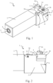
- the turning tool holder 1 is described below with reference to the Fig. 1 to Fig. 12 described.
- the turning tool holder 1 is designed as a so-called monoblock holder, but it should be noted that the turning tool holder 1 can also have other designs.
- the turning tool holder 1 has a clamping section 2 for clamping to a tool holder of a processing machine and a processing section 3 which is formed in one piece or monolithically with the clamping section 2 and on which a seat 4 is formed for receiving an exchangeable cutting insert 20.
- the turning tool holder 1 can be made of steel or a relatively tough hard metal, for example.
- the specific example shows an implementation in which the seat 4 is designed such that the cutting insert 20 is fastened to the seat 4 via a fastening screw 21, other conventional designs are also possible, such as fastening via a clamping claw or the like.
- the cutting edge 22 which comes into engagement with the material to be machined is formed in a manner known per se on the cutting insert 20.
- the cutting insert 20 is made of a hard and wear-resistant material and can in particular be made of cemented carbide, cermet or a cutting ceramic.
- the cutting insert 20 can in particular, it can be designed as an indexable insert which has a plurality of cutting areas which can be used one after the other.
- the turning tool holder 1 has an internal coolant guide which is designed to supply coolant through the interior of the turning tool holder 1 to the machining section 3.
- the internal coolant guide has at least one first coolant inlet 5, via which coolant can be supplied into the internal coolant guide.
- first coolant inlet 5 is shown, which is formed on one end face of the clamping section 2
- the turning tool holder 1 can preferably have a plurality of alternatively usable coolant inlets 5, which are each connected in a communicating manner to the internal coolant guide.
- the coolant inlets which are not specifically required can be closed with a closure element 6, as shown in Fig. 1 is shown as an example for the first coolant inlet 5.
- the turning tool holder 1 in the concrete example shown has a first coolant outlet 7a and a further coolant outlet 7b, which are each formed on an upper surface 8 of the machining section 3 laterally from the seat 4. Both the first coolant outlet 7a and the second coolant outlet 7b are designed in the embodiment to supply coolant to a chip surface of the replaceable cutting insert 20.
- the embodiment further comprises a third coolant outlet 9 which is also in fluid communication with the internal coolant guide and via which coolant can be supplied to a free surface of the cutting insert 20.
- first coolant outlet 7a and the further coolant outlet 7b are essentially identical to one another apart from their spatial position, only the first coolant outlet 7a is described in more detail below and the description applies equally to the further coolant outlet 7b.
- the first coolant outlet 7a has a bore 10 which extends from the surface 8 of the machining section 3 into the material of the turning tool holder 1 and is in fluid communication with the first coolant inlet 5 and possibly further coolant inlets (if present) via the internal coolant guide.
- the bore 10 is designed as a cylindrical bore whose longitudinal axis extends perpendicular to the surface 8.
- the bore 10 is provided in particular with a smooth wall.
- a replaceable nozzle body 30 is inserted in the bore 10 of the first coolant outlet 7a, which is described in more detail below.
- the nozzle body 30 can preferably be made of a different material than the rest of the turning tool holder, in particular of a harder and more wear-resistant material.
- the nozzle body 30 can be made of hard metal. In this case, it is particularly resistant to wear caused by running off chips.
- the nozzle body 30 is in the Fig. 3 and Fig. 4 furthermore also shown individually.
- the nozzle body 30 is formed in one piece or monolithically and has a shaft region 31 which is designed such that it can be inserted into the bore 10 and a nozzle outlet region 32 which is angled thereto.
- the shaft region 31 is formed rotationally symmetrically with respect to a longitudinal axis L which is in Fig. 4 is shown schematically.
- an annular circumferential recess is formed on the outer circumference of the shaft region, in which an annular sealing element 40 is arranged.
- the annular sealing element 40 is realized as an O-ring made of rubber.
- the shaft region 31 and the annular sealing element 40 are dimensioned such that the shaft region 31 can be introduced into the bore 10 and the annular sealing element 40 is arranged sealingly between the outer circumferential surface of the shaft region 31 and the inner circumferential surface of the bore 10. In this way, the annular sealing element 40 prevents undesired coolant passage between the outer peripheral surface of the shaft area 31 and the inner peripheral surface of the bore 10.
- the angled nozzle outlet region 32 of the nozzle body 30 is aligned such that an underside of the nozzle outlet region 32 rests on the surface 8 of the machining section 3 when the shaft region 31 is inserted into the bore 10.
- a first anti-twist element 11 is arranged on the surface 8 of the machining section 3, which interacts with a second anti-twist element 33 that is arranged on the underside of the nozzle outlet region 32.
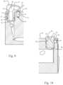
- the second anti-twist element 33 is designed as a recess in the underside of the nozzle outlet region 32 and the first anti-twist element 11 is designed as a projection engaging therein, as shown in particular in Fig. 9 can be seen.
- This can be implemented in a particularly simple and cost-effective manner.
- a reverse design is also possible, in which the first anti-twisting element 11 is designed as a recess and the second anti-twisting element 33 as a projection.
- the first anti-twisting element 11 is formed by a pin 12 which is inserted into a bore 13 extending from the surface 8 of the processing section 3, which enables a particularly cost-effective implementation.
- the pin 12 can, for example, be pressed into a smooth-walled bore 13 or the pin 12 can be provided with an external thread which interacts with a corresponding internal thread in the bore 13.
- the nozzle body 30 has an outlet opening 35 for a coolant jet at the nozzle outlet area 32, which is aligned via the interaction of the first anti-twist element 11 and the second anti-twist element 33 such that the coolant jet is directed onto a chip surface of a cutting insert 20 arranged on the seat 4.
- An inner coolant channel 36 extends through the shaft region 31 and the nozzle outlet region 32 angled thereto, said channel being designed to guide coolant from the inner coolant guide to the outlet opening 35.
- the inner coolant channel 36 extends through the nozzle body 30 in a spatially curved manner and is free of abrupt cross-sectional changes, so that the coolant in the nozzle body 30 is gently deflected in the direction of the outlet opening 35.
- the inner coolant channel 36 extends essentially parallel and coaxially to the longitudinal axis L.
- the shaft area 31 of the nozzle body 30 is provided with a recess 37.
- the recess 37 is designed in the embodiment as a ring-shaped groove running around the shaft area 31.
- the groove runs in particular coaxially to the longitudinal axis L in a ring-shaped manner, which enables particularly simple and cost-effective production.
- the recess 37 also has a substantially trapezoidal cross-sectional profile, as in Fig. 4 and in Fig. 6 As can be seen particularly in Fig. 6
- a transverse bore 14 is formed in the machining section 3 of the turning tool holder 1 and is connected to the bore 10 in a communicating manner.
- the transverse bore 14 extends transversely to the bore 10 and consequently also transversely to the longitudinal axis L of the shaft region 31.
- the transverse bore 14 can extend perpendicularly to the longitudinal axis L.
- the transverse bore 14 is formed as a threaded bore with an internal thread and extends to a side surface of the machining section 3.
- a clamping element 16 is arranged in the transverse bore 14 and is designed to engage in the recess 37 on the shaft area 31 in order to fasten the nozzle body 30 to the processing section 3.
- the clamping element 16 is provided with an external thread which is connected to the Internal thread in the transverse bore 14.
- a side of the clamping element 16 facing away from the bore 10 is provided with an engagement structure for a screwing tool, via which the clamping element 16 can be actuated with a screwing tool that is introduced into the transverse bore from the side surface of the processing section 3.
- the engagement structure can be designed, for example, as a slot for a slotted screwdriver, as a Phillips slot, as an internal hexagon or the like.
- the clamping element 16 is designed as a grub screw in the specific embodiment shown.
- the recess 37 on the shaft region 31 of the nozzle body 30 has a clamping surface 37a which runs obliquely to the longitudinal axis L of the shaft region 31 and is caused by the trapezoidal cross-sectional profile of the recess 37.
- the clamping surface 37a is aligned obliquely in such a way that it moves away from the longitudinal axis L with increasing distance from the nozzle outlet region 32, i.e. the outer circumference of the shaft region 31 widens with increasing distance from the nozzle outlet region 32.
- the end face of the clamping element 16 facing the bore 10 is laterally bevelled or chamfered so that a holding surface 16a which also runs obliquely to the longitudinal axis L is formed.
- the outer circumference of the clamping element 16 thus tapers in the direction of the bore 10.
- the position of the recess 37 on the shaft area 31 and the position of the transverse bore 14 are coordinated with one another in such a way that the holding surface 16a of the clamping element 16 acts in a wedge-shaped manner according to the principle of the inclined plane on the clamping surface 37a of the recess 37 in such a way that the nozzle body 30 is pulled into the bore 10 when the clamping element 16 is screwed into the transverse bore 14. In this way, the nozzle body 30 is clamped against the surface 8 of the processing section 3, whereby the first anti-twisting element 11 and the second anti-twisting element 33 are also held in positive engagement.
- the recess 37 is on the shaft area 31 between the nozzle outlet area 32 and the annular sealing element 40 so that the clamping mechanism formed by the clamping element 16 and the recess 37 is protected from the coolant.
- the further coolant outlet 7b is designed in a manner corresponding to the first coolant outlet 7a. Consequently, a bore 10 and a transverse bore 14 with a clamping element 16 are also provided and a first anti-twisting element 11 is also provided on the surface 8 of the machining section 3.
- the nozzle body 30 can be inserted either into the bore 10 of the first coolant outlet 7a or into the bore 10 of the further coolant outlet 7b. Furthermore, it is possible, for example, to insert a nozzle body 30 into both the bore 10 of the first coolant outlet 7a and the bore 10 of the second coolant outlet 7b, as is shown, for example, in Fig. 11 is shown.
- the bore 10 of the first coolant outlet 7a or the bore 10 of the further coolant outlet 7b can be closed with a blind plug 50, which is described below.
- a blind plug 50 which is described below.
- both the first coolant outlet 7a nor the second coolant outlet 7b can be closed with respective blind plugs 50.
- the blind plug 50 is in Fig. 8 shown in a side view without an annular sealing element 40, in Fig. 7 in a perspective view with an annular sealing element 40 arranged thereon.
- the Blind plug 50 has a shaft portion 51, the outer peripheral surface of which is substantially identical to the shaft portion 31 of the nozzle body 30, as shown in the Fig. 7 and Fig. 8 can be seen.
- the annular sealing element 40 is not shown.
- the shaft region 51 of the blind plug has a recess 37 with a clamping surface 37a and a circumferential depression in which the annular sealing element 40 is received.
- the blind plug 50 has a flat cover region 52 which has a slightly larger cross section than the bore 10 and which is designed to be so flat that it does not protrude greatly from the surface 8 of the processing section 3 when the shaft section 51 is received in the bore 10.
- the blind plug 50 can be fastened in the same way with the clamping element 16 in the bore 10 of the first coolant outlet 7a and in the bore of the second coolant outlet 7b as was previously described for the nozzle body 30.
Landscapes
- Engineering & Computer Science (AREA)
- Mechanical Engineering (AREA)
- Cutting Tools, Boring Holders, And Turrets (AREA)
- Auxiliary Devices For Machine Tools (AREA)
Claims (13)
- Système d'outil de tournage comportant un support d'outil de tournage (1), le support d'outil de tournage (1) ayant :une partie de serrage (2) servant à la liaison à un logement d'outil d'une machine d'usinage etune partie d'usinage (3) comportant un siège (4) servant au logement d'un insert de coupe (20) interchangeable, un guide de réfrigérant servant à l'acheminement de réfrigérant jusqu'à la partie d'usinage (3) étant réalisé dans le support d'outil de tournage (1), lequel guide présente au moins une première entrée de réfrigérant (5) et au moins une première sortie de réfrigérant (7a) disposée latéralement par rapport au siège (4) sur la partie d'usinage (3),la première sortie de réfrigérant (7a) présentant un alésage (10) disposé latéralement par rapport au siège (4), s'étendant à partir d'une surface (8) de la partie d'usinage (3), alésage dans lequel est inséré un corps de buse (30) interchangeable qui a une région tige (31) insérée dans l'alésage (10) et une région de sortie de buse (32) réalisée de manière inclinée par rapport à celle-ci, disposée sur la surface (8) de la partie d'usinage (3),un canal de réfrigérant intérieur (36) s'étendant à travers la région tige (31) et la région de sortie de buse (32) inclinée par rapport à celle-ci, caractérisé en ce quela région tige (31) présente, sur une surface périphérique extérieure, un évidement (37) dans lequel vient en prise un élément de serrage (16) disposé dans le support d'outil de tournage (1), disposé transversalement par rapport à un axe longitudinal (L) de la région tige (31), élément de serrage à l'aide duquel le corps de buse (30) est fixé au support d'outil de tournage (1) ;au moins une autre sortie de réfrigérant (7b) comportant un alésage (10) s'étendant à partir de la surface (8) est réalisée sur la partie d'usinage (3) latéralement par rapport au siège (4),la première sortie de réfrigérant (7a) et l'autre sortie de réfrigérant (7b) sont réalisées de telle sorte que le corps de buse (30) peut être inséré sélectivement dans l'alésage (10) de la première sortie de réfrigérant (7a) ou dans l'alésage (10) de l'autre sortie de réfrigérant (7b),et le système d'outil de tournage a au moins un bouchon borgne (50)qui peut être inséré au lieu du corps de buse (30) dans l'alésage (10) de la première sortie de réfrigérant (7a) ou dans l'alésage de l'autre sortie de réfrigérant (7b), afin de fermer ceux-ci de manière étanche aux fluides.
- Système d'outil de tournage selon la revendication 1, l'élément de serrage (16) étant disposé dans un alésage transversal (14) relié de manière communicante à l'alésage (10).
- Système d'outil de tournage selon la revendication 2, l'alésage transversal (14) étant un alésage fileté comportant un filetage intérieur qui coopère avec un filetage extérieur sur l'élément de serrage (16).
- Système d'outil de tournage selon l'une des revendications 1 à 3, l'évidement (37) étant une rainure entourant de manière annulaire la région tige (31).
- Système d'outil de tournage selon l'une des revendications précédentes, l'évidement (37) présentant une surface de serrage (37a) s'étendant de manière oblique par rapport à un axe longitudinal (L) de la région tige (31), surface sur laquelle agit en forme de coin une surface de retenue (16a) de l'élément de serrage (16), de sorte que le corps de buse (30) soit serré contre la surface (8) de la partie d'usinage (3).
- Système d'outil de tournage selon l'une des revendications précédentes, un premier élément de fixation antirotation (11) étant disposé sur la surface (8) de la partie d'usinage (3), lequel coopère avec un deuxième élément de fixation antirotation (33) sur un côté inférieur de la région de sortie de buse (32) pour empêcher une rotation du corps de buse (30) autour d'un axe longitudinal (L) de la région tige (31).
- Système d'outil de tournage selon la revendication 6, le premier élément de fixation antirotation (11) étant une saillie et la deuxième fixation antirotation (33) étant un renfoncement dans le côté inférieur de la région de sortie de buse (32).
- Système d'outil de tournage selon l'une des revendications précédentes, la première sortie de réfrigérant (7a) étant disposée de telle sorte qu'un jet de réfrigérant sortant du corps de buse (30) est orienté vers une face de coupe d'un insert de coupe (20) disposé sur le siège (4).
- Système d'outil de tournage selon l'une des revendications précédentes, un élément d'étanchéité annulaire (40) étant disposé entre une surface périphérique extérieure de la région tige (31) et une surface périphérique intérieure de l'alésage (10).
- Système d'outil de tournage selon la revendication 9, l'élément d'étanchéité (40) étant disposé sur un côté de l'évidement (37) opposé à la région de sortie de buse (32).
- Système d'outil de tournage selon l'une des revendications précédentes, le canal de réfrigérant (36) réalisé dans le corps de buse (30) étant dépourvu de changements abrupts de section transversale.
- Système d'outil de tournage selon l'une des revendications précédentes, le canal de réfrigérant (36) s'étendant de manière incurvée spatialement à travers le corps de buse (30).
- Système d'outil de tournage selon l'une des revendications précédentes, le corps de buse (30) étant réalisé à partir d'un autre matériau que le reste du support d'outil de tournage (1).
Applications Claiming Priority (2)
| Application Number | Priority Date | Filing Date | Title |
|---|---|---|---|
| ATGM155/2018U AT16570U1 (de) | 2018-08-01 | 2018-08-01 | Drehwerkzeug-Halter |
| PCT/AT2019/060210 WO2020023985A1 (fr) | 2018-08-01 | 2019-06-27 | Support d'outil de tournage |
Publications (3)
| Publication Number | Publication Date |
|---|---|
| EP3829802A1 EP3829802A1 (fr) | 2021-06-09 |
| EP3829802C0 EP3829802C0 (fr) | 2025-02-19 |
| EP3829802B1 true EP3829802B1 (fr) | 2025-02-19 |
Family
ID=69146827
Family Applications (1)
| Application Number | Title | Priority Date | Filing Date |
|---|---|---|---|
| EP19739852.2A Active EP3829802B1 (fr) | 2018-08-01 | 2019-06-27 | Système d'outils de tournage avec support d'outil de tournage |
Country Status (8)
| Country | Link |
|---|---|
| US (1) | US20210308773A1 (fr) |
| EP (1) | EP3829802B1 (fr) |
| JP (1) | JP7312243B2 (fr) |
| KR (1) | KR102560935B1 (fr) |
| CN (1) | CN112351851B (fr) |
| AT (1) | AT16570U1 (fr) |
| ES (1) | ES3015170T3 (fr) |
| WO (1) | WO2020023985A1 (fr) |
Families Citing this family (6)
| Publication number | Priority date | Publication date | Assignee | Title |
|---|---|---|---|---|
| EP3623083B1 (fr) * | 2018-09-11 | 2022-11-09 | Walter Ag | Outil de tournage |
| JP7559650B2 (ja) * | 2021-03-30 | 2024-10-02 | 三菱マテリアル株式会社 | クーラント吐出部材および刃先交換式切削工具 |
| CN113695610B (zh) * | 2021-09-03 | 2022-08-05 | 哈尔滨理工大学 | 一种省力车刀仿生设计方法 |
| WO2023079549A1 (fr) * | 2021-11-04 | 2023-05-11 | No Screw Ltd. | Plaquette de coupe avec canaux de refroidissement, buse, plaque de base et porte-outil pour celui-ci |
| CN114425628B (zh) * | 2022-04-07 | 2022-07-19 | 长沙学院 | 一种塔式起重机标准节加工中心及加工方法 |
| CN120715240B (zh) * | 2025-09-01 | 2025-10-31 | 泰州同创展示道具有限公司 | 一种五金配件车削设备 |
Citations (4)
| Publication number | Priority date | Publication date | Assignee | Title |
|---|---|---|---|---|
| DE2234389A1 (de) * | 1972-07-13 | 1974-01-24 | Bernhard Rau | Aufnahmevorrichtung fuer auswechselbare werkzeugkoepfe bei bohrstangen |
| US4848198A (en) * | 1988-04-21 | 1989-07-18 | Kennametal Inc. | Chip breaking tool holder |
| JPH07266104A (ja) * | 1994-03-23 | 1995-10-17 | Toshiba Tungaloy Co Ltd | バイト |
| US20130220089A1 (en) * | 2012-02-23 | 2013-08-29 | Iscar, Ltd. | Cutting tool with internal fluid delivery system |
Family Cites Families (41)
| Publication number | Priority date | Publication date | Assignee | Title |
|---|---|---|---|---|
| DE600758C (de) * | 1933-07-04 | 1934-07-31 | Wlodzimierz Zagrodzki | Runder Formstahl fuer die Metallbearbeitung durch Drehen u. a. mit in der Umfangsrichtung unterteiltem Schneidenteil |
| US4699047A (en) * | 1985-01-25 | 1987-10-13 | Nabisco Brands, Inc. | Paste spreader apparatus for shredded wheat |
| JP2701514B2 (ja) * | 1989-06-15 | 1998-01-21 | 三菱マテリアル株式会社 | スローアウエイチップのクランプ機構 |
| MX9205453A (es) * | 1992-09-25 | 1994-05-31 | Kennametal Inc | Portaherramientas para romper astillas con tapa deorificio ajustable. |
| JP3317783B2 (ja) * | 1994-07-08 | 2002-08-26 | 東芝タンガロイ株式会社 | 旋削工具 |
| JPH08257807A (ja) * | 1995-03-24 | 1996-10-08 | Toshiba Tungaloy Co Ltd | 給油穴付きのバイト |
| JPH09183002A (ja) * | 1995-12-29 | 1997-07-15 | Sumitomo Electric Ind Ltd | 内部給油式バイト |
| JPH1076404A (ja) * | 1996-02-28 | 1998-03-24 | Sumitomo Electric Ind Ltd | 旋削用バイト |
| AU7716098A (en) * | 1997-06-05 | 1998-12-21 | Gregory S. Antoun | Tool holder with integral coolant passage and replaceable nozzle |
| SE513480C2 (sv) * | 1998-01-27 | 2000-09-18 | Sandvik Ab | Skärverktyg |
| SE514938C2 (sv) * | 1999-09-02 | 2001-05-21 | Sandvik Ab | Skärverktyg |
| US7097257B2 (en) * | 2004-09-15 | 2006-08-29 | Sandvik Intellectual Property Ab | Cutting tool with nozzle for spraying water on cutter bit |
| AT9195U1 (de) * | 2006-01-30 | 2007-06-15 | Ceratizit Austria Gmbh | Schneidwerkzeug |
| US20070283794A1 (en) * | 2006-06-13 | 2007-12-13 | Giannetti Enrico R | Machine tool holder having internal coolant supply and cutter retaining and coolant distribution cutter insert retaining clamp assembly |
| SE530581C2 (sv) * | 2006-11-28 | 2008-07-08 | Sandvik Intellectual Property | Verktyg och grundkropp för spånavskiljande innefattande två kanaler för en fluid |
| US7883299B2 (en) * | 2007-01-18 | 2011-02-08 | Kennametal Inc. | Metal cutting system for effective coolant delivery |
| US7762166B2 (en) * | 2007-02-28 | 2010-07-27 | Giannetti Enrico R | Multiple machine tool support block and tool post having internal coolant supply |
| DE202007009943U1 (de) * | 2007-07-17 | 2007-09-13 | Kennametal Inc. | Werkzeughalter mit Schneideinsatz |
| IL204235A (en) * | 2010-03-02 | 2013-04-30 | Iscar Ltd | Variable cooling distribution for milling with elongated release canal |
| IL206283A0 (en) * | 2010-06-10 | 2010-11-30 | Iscar Ltd | Cutting tool and nozzle therefor |
| AU2011333341A1 (en) * | 2010-11-24 | 2013-07-11 | No Screw Ltd. | Cutting tool with cooling mechanism and a cutting insert and tool holder therefor |
| DE102011016148B4 (de) * | 2011-03-28 | 2024-06-06 | Hartmetall-Werkzeugfabrik Paul Horn Gmbh | Werkzeug zur spanenden Bearbeitung eines Werkstücks mit seitlichem Kühlmittelaustritt und Halter für das Werkzeug |
| DE102012219490A1 (de) * | 2011-10-26 | 2013-05-02 | Ceramtec Gmbh | Werkzeugsystem |
| US8827598B2 (en) * | 2011-11-22 | 2014-09-09 | Kennametal Inc. | Cutting assembly with enhanced coolant delivery |
| US8573900B1 (en) * | 2012-04-19 | 2013-11-05 | Iscar, Ltd. | Cutting tool and cutting tool holder having lever pin |
| US8985913B2 (en) * | 2012-11-13 | 2015-03-24 | Iscar, Ltd. | Cutting tool holder with internal coolant passage having a compressible member |
| DE102013100104B4 (de) * | 2013-01-08 | 2022-08-11 | Kennametal Inc. | Rotations-Schneidwerkzeug und Werkzeugeinheit |
| US20140270999A1 (en) * | 2013-03-16 | 2014-09-18 | Hsien-Jen Huang | Coolant delivery device for cutting tools |
| US9427807B2 (en) * | 2013-05-13 | 2016-08-30 | Dennis P. Flolo | Clamp to hold a cutting insert on a tool holder |
| US9387538B2 (en) * | 2013-05-31 | 2016-07-12 | Ntm, Inc. | Tool holder for machine tool, machine tool assembly, and methods |
| EP2813305B1 (fr) * | 2013-06-12 | 2016-03-23 | Satisloh AG | Tour Fast Tool |
| KR101958072B1 (ko) * | 2013-10-18 | 2019-03-13 | 니뽄 도쿠슈 도교 가부시키가이샤 | 바이트용 홀더 및 절삭 공구 |
| JP6550759B2 (ja) * | 2015-01-23 | 2019-07-31 | 三菱マテリアル株式会社 | バイト |
| CN204725233U (zh) * | 2015-05-26 | 2015-10-28 | 无锡金球机械有限公司 | 数控刨槽机气动冷却装置 |
| EP3112063B1 (fr) * | 2015-06-30 | 2023-08-09 | Seco Tools Ab | Outil de coupe |
| US10596634B2 (en) * | 2015-06-30 | 2020-03-24 | Seco Tools Ab | Cutting tool with a nozzle with a coolant channel |
| WO2017056969A1 (fr) * | 2015-09-29 | 2017-04-06 | 株式会社タンガロイ | Élément d'ancrage d'insert de coupe et outil de coupe |
| JP6874292B2 (ja) * | 2016-07-21 | 2021-05-19 | 三菱マテリアル株式会社 | バイト |
| JP2018012172A (ja) * | 2016-07-21 | 2018-01-25 | 三菱マテリアル株式会社 | バイト |
| EP3219421A1 (fr) * | 2016-09-09 | 2017-09-20 | Seco Tools Ab | Porte-outils avec conduits d'alimentation en fluide pour co2 supercritique |
| CN107829688B (zh) * | 2017-11-21 | 2024-04-12 | 中南大学 | 一种旋冲震荡射流式pdc钻头 |
-
2018
- 2018-08-01 AT ATGM155/2018U patent/AT16570U1/de not_active IP Right Cessation
-
2019
- 2019-06-27 WO PCT/AT2019/060210 patent/WO2020023985A1/fr not_active Ceased
- 2019-06-27 CN CN201980044292.XA patent/CN112351851B/zh active Active
- 2019-06-27 ES ES19739852T patent/ES3015170T3/es active Active
- 2019-06-27 KR KR1020217005145A patent/KR102560935B1/ko active Active
- 2019-06-27 EP EP19739852.2A patent/EP3829802B1/fr active Active
- 2019-06-27 JP JP2021505766A patent/JP7312243B2/ja active Active
- 2019-06-27 US US17/264,933 patent/US20210308773A1/en not_active Abandoned
Patent Citations (4)
| Publication number | Priority date | Publication date | Assignee | Title |
|---|---|---|---|---|
| DE2234389A1 (de) * | 1972-07-13 | 1974-01-24 | Bernhard Rau | Aufnahmevorrichtung fuer auswechselbare werkzeugkoepfe bei bohrstangen |
| US4848198A (en) * | 1988-04-21 | 1989-07-18 | Kennametal Inc. | Chip breaking tool holder |
| JPH07266104A (ja) * | 1994-03-23 | 1995-10-17 | Toshiba Tungaloy Co Ltd | バイト |
| US20130220089A1 (en) * | 2012-02-23 | 2013-08-29 | Iscar, Ltd. | Cutting tool with internal fluid delivery system |
Also Published As
| Publication number | Publication date |
|---|---|
| CN112351851A (zh) | 2021-02-09 |
| JP7312243B2 (ja) | 2023-07-20 |
| US20210308773A1 (en) | 2021-10-07 |
| KR20210042924A (ko) | 2021-04-20 |
| WO2020023985A1 (fr) | 2020-02-06 |
| ES3015170T3 (en) | 2025-04-29 |
| CN112351851B (zh) | 2023-07-21 |
| JP2022503506A (ja) | 2022-01-12 |
| EP3829802C0 (fr) | 2025-02-19 |
| KR102560935B1 (ko) | 2023-07-27 |
| EP3829802A1 (fr) | 2021-06-09 |
| AT16570U1 (de) | 2020-01-15 |
Similar Documents
| Publication | Publication Date | Title |
|---|---|---|
| EP3829802B1 (fr) | Système d'outils de tournage avec support d'outil de tournage | |
| DE69727338T2 (de) | Schnell auswechselbare Düsenanordnung zum Wasserstrahlschneiden | |
| DE112011102930B4 (de) | Schneideinsatz-Anordnung und Schneidanordnung | |
| DE69902371T2 (de) | Schneidwerkzeug mit düse | |
| EP2666567B1 (fr) | Dispositif porte-outil | |
| DE69520147T3 (de) | Werkzeugschaft mit abnehmbaren ende | |
| AT396663B (de) | Spannbüchse, insbesondere federnde klemmhülse | |
| EP3501701A1 (fr) | Système d'outillage et procédé d'usinage par tournage | |
| DE112017004141B4 (de) | Schneidwerkzeug und Verfahren zur Herstellung eines maschinell-bearbeiteten Produkts unter Verwendung desselben | |
| DE102015108904A1 (de) | Werkzeughalter mit verbesserter interner Kühlmittelzufuhr | |
| EP2911817B1 (fr) | Dispositif de serrage avec coin doté d'un conduit de fluide de refroidissement et procédé de fabrication d'un tel dispositif de serrage | |
| EP2999566B1 (fr) | Outil rotatif avec alimentation interne de fluide de refroidissement et/ou de lubrifiant | |
| DE112016006041B4 (de) | Halter für ein Schneidwerkzeug, Schneidwerkzeug und Verfahren zum Herstellen eines maschinell-bearbeiteten Produkts | |
| WO2019097074A1 (fr) | Outil de filetage à la volée | |
| EP1536905B1 (fr) | Outil a percer presentant des matrices de decoupage alternatif, et matrices de decoupage alternatif destinees a un outil a percer de ce type | |
| DE19861489B4 (de) | Verfahren und Vorrichtung zur Einspeisung von Kühl- und Schmiermittel in ein Werkzeug | |
| DE4307280A1 (de) | Werkzeughalter | |
| DE102014116856A1 (de) | Kombinationswerkzeug zur Bearbeitung von Zylinderbohrungen | |
| EP3170601B1 (fr) | Dispositif de moulage ou de taraudage de filets et procédé de fabrication d'un dispositif de moulage ou de taraudage de filets | |
| WO2018029013A1 (fr) | Logement d'outil | |
| DE3033626A1 (de) | Drehmeissel | |
| DE69428746T3 (de) | Ein Metallschneidewerkzeug | |
| EP2283954B1 (fr) | Plaquette de coupe pour un outil de façonnage et outil de façonnage | |
| DE10227687A1 (de) | Vorrichtung zum Leiten eines fluiden Mediums zum Arbeitsbereich eines Gewindeerzeugungswerkzeuges | |
| DE202017007546U1 (de) | Wirbelwerkzeug |
Legal Events
| Date | Code | Title | Description |
|---|---|---|---|
| STAA | Information on the status of an ep patent application or granted ep patent |
Free format text: STATUS: UNKNOWN |
|
| STAA | Information on the status of an ep patent application or granted ep patent |
Free format text: STATUS: THE INTERNATIONAL PUBLICATION HAS BEEN MADE |
|
| PUAI | Public reference made under article 153(3) epc to a published international application that has entered the european phase |
Free format text: ORIGINAL CODE: 0009012 |
|
| STAA | Information on the status of an ep patent application or granted ep patent |
Free format text: STATUS: REQUEST FOR EXAMINATION WAS MADE |
|
| 17P | Request for examination filed |
Effective date: 20201216 |
|
| AK | Designated contracting states |
Kind code of ref document: A1 Designated state(s): AL AT BE BG CH CY CZ DE DK EE ES FI FR GB GR HR HU IE IS IT LI LT LU LV MC MK MT NL NO PL PT RO RS SE SI SK SM TR |
|
| DAV | Request for validation of the european patent (deleted) | ||
| DAX | Request for extension of the european patent (deleted) | ||
| STAA | Information on the status of an ep patent application or granted ep patent |
Free format text: STATUS: EXAMINATION IS IN PROGRESS |
|
| 17Q | First examination report despatched |
Effective date: 20240620 |
|
| GRAP | Despatch of communication of intention to grant a patent |
Free format text: ORIGINAL CODE: EPIDOSNIGR1 |
|
| STAA | Information on the status of an ep patent application or granted ep patent |
Free format text: STATUS: GRANT OF PATENT IS INTENDED |
|
| RIC1 | Information provided on ipc code assigned before grant |
Ipc: B23Q 11/10 20060101ALI20240927BHEP Ipc: B23B 27/10 20060101AFI20240927BHEP |
|
| INTG | Intention to grant announced |
Effective date: 20241106 |
|
| GRAS | Grant fee paid |
Free format text: ORIGINAL CODE: EPIDOSNIGR3 |
|
| GRAA | (expected) grant |
Free format text: ORIGINAL CODE: 0009210 |
|
| STAA | Information on the status of an ep patent application or granted ep patent |
Free format text: STATUS: THE PATENT HAS BEEN GRANTED |
|
| AK | Designated contracting states |
Kind code of ref document: B1 Designated state(s): AL AT BE BG CH CY CZ DE DK EE ES FI FR GB GR HR HU IE IS IT LI LT LU LV MC MK MT NL NO PL PT RO RS SE SI SK SM TR |
|
| REG | Reference to a national code |
Ref country code: GB Ref legal event code: FG4D Free format text: NOT ENGLISH |
|
| REG | Reference to a national code |
Ref country code: CH Ref legal event code: EP |
|
| REG | Reference to a national code |
Ref country code: IE Ref legal event code: FG4D Free format text: LANGUAGE OF EP DOCUMENT: GERMAN |
|
| REG | Reference to a national code |
Ref country code: DE Ref legal event code: R096 Ref document number: 502019012959 Country of ref document: DE |
|
| U01 | Request for unitary effect filed |
Effective date: 20250220 |
|
| U07 | Unitary effect registered |
Designated state(s): AT BE BG DE DK EE FI FR IT LT LU LV MT NL PT RO SE SI Effective date: 20250227 |
|
| REG | Reference to a national code |
Ref country code: ES Ref legal event code: FG2A Ref document number: 3015170 Country of ref document: ES Kind code of ref document: T3 Effective date: 20250429 |
|
| PG25 | Lapsed in a contracting state [announced via postgrant information from national office to epo] |
Ref country code: RS Free format text: LAPSE BECAUSE OF FAILURE TO SUBMIT A TRANSLATION OF THE DESCRIPTION OR TO PAY THE FEE WITHIN THE PRESCRIBED TIME-LIMIT Effective date: 20250519 |
|
| PG25 | Lapsed in a contracting state [announced via postgrant information from national office to epo] |
Ref country code: PL Free format text: LAPSE BECAUSE OF FAILURE TO SUBMIT A TRANSLATION OF THE DESCRIPTION OR TO PAY THE FEE WITHIN THE PRESCRIBED TIME-LIMIT Effective date: 20250219 |
|
| PGFP | Annual fee paid to national office [announced via postgrant information from national office to epo] |
Ref country code: GB Payment date: 20250618 Year of fee payment: 7 |
|
| PG25 | Lapsed in a contracting state [announced via postgrant information from national office to epo] |
Ref country code: IS Free format text: LAPSE BECAUSE OF FAILURE TO SUBMIT A TRANSLATION OF THE DESCRIPTION OR TO PAY THE FEE WITHIN THE PRESCRIBED TIME-LIMIT Effective date: 20250619 Ref country code: NO Free format text: LAPSE BECAUSE OF FAILURE TO SUBMIT A TRANSLATION OF THE DESCRIPTION OR TO PAY THE FEE WITHIN THE PRESCRIBED TIME-LIMIT Effective date: 20250519 |
|
| PG25 | Lapsed in a contracting state [announced via postgrant information from national office to epo] |
Ref country code: HR Free format text: LAPSE BECAUSE OF FAILURE TO SUBMIT A TRANSLATION OF THE DESCRIPTION OR TO PAY THE FEE WITHIN THE PRESCRIBED TIME-LIMIT Effective date: 20250219 |
|
| PG25 | Lapsed in a contracting state [announced via postgrant information from national office to epo] |
Ref country code: GR Free format text: LAPSE BECAUSE OF FAILURE TO SUBMIT A TRANSLATION OF THE DESCRIPTION OR TO PAY THE FEE WITHIN THE PRESCRIBED TIME-LIMIT Effective date: 20250520 |
|
| U20 | Renewal fee for the european patent with unitary effect paid |
Year of fee payment: 7 Effective date: 20250627 |
|
| PG25 | Lapsed in a contracting state [announced via postgrant information from national office to epo] |
Ref country code: SM Free format text: LAPSE BECAUSE OF FAILURE TO SUBMIT A TRANSLATION OF THE DESCRIPTION OR TO PAY THE FEE WITHIN THE PRESCRIBED TIME-LIMIT Effective date: 20250219 |
|
| PGFP | Annual fee paid to national office [announced via postgrant information from national office to epo] |
Ref country code: ES Payment date: 20250731 Year of fee payment: 7 |
|
| PGFP | Annual fee paid to national office [announced via postgrant information from national office to epo] |
Ref country code: CH Payment date: 20250701 Year of fee payment: 7 |
|
| PG25 | Lapsed in a contracting state [announced via postgrant information from national office to epo] |
Ref country code: CZ Free format text: LAPSE BECAUSE OF FAILURE TO SUBMIT A TRANSLATION OF THE DESCRIPTION OR TO PAY THE FEE WITHIN THE PRESCRIBED TIME-LIMIT Effective date: 20250219 |
|
| PG25 | Lapsed in a contracting state [announced via postgrant information from national office to epo] |
Ref country code: SK Free format text: LAPSE BECAUSE OF FAILURE TO SUBMIT A TRANSLATION OF THE DESCRIPTION OR TO PAY THE FEE WITHIN THE PRESCRIBED TIME-LIMIT Effective date: 20250219 |
|
| PLBE | No opposition filed within time limit |
Free format text: ORIGINAL CODE: 0009261 |
|
| STAA | Information on the status of an ep patent application or granted ep patent |
Free format text: STATUS: NO OPPOSITION FILED WITHIN TIME LIMIT |
|
| 26N | No opposition filed |
Effective date: 20251120 |
|
| PG25 | Lapsed in a contracting state [announced via postgrant information from national office to epo] |
Ref country code: MC Free format text: LAPSE BECAUSE OF FAILURE TO SUBMIT A TRANSLATION OF THE DESCRIPTION OR TO PAY THE FEE WITHIN THE PRESCRIBED TIME-LIMIT Effective date: 20250219 |
|
| PG25 | Lapsed in a contracting state [announced via postgrant information from national office to epo] |
Ref country code: IE Free format text: LAPSE BECAUSE OF NON-PAYMENT OF DUE FEES Effective date: 20250627 |