EP0467080B1 - Lichtübertragungssystem - Google Patents
Lichtübertragungssystem Download PDFInfo
- Publication number
- EP0467080B1 EP0467080B1 EP91109963A EP91109963A EP0467080B1 EP 0467080 B1 EP0467080 B1 EP 0467080B1 EP 91109963 A EP91109963 A EP 91109963A EP 91109963 A EP91109963 A EP 91109963A EP 0467080 B1 EP0467080 B1 EP 0467080B1
- Authority
- EP
- European Patent Office
- Prior art keywords
- optical
- optical fiber
- coupled
- piece
- communication system
- Prior art date
- Legal status (The legal status is an assumption and is not a legal conclusion. Google has not performed a legal analysis and makes no representation as to the accuracy of the status listed.)
- Expired - Lifetime
Links
Images

Classifications
-
- H—ELECTRICITY
- H04—ELECTRIC COMMUNICATION TECHNIQUE
- H04B—TRANSMISSION
- H04B10/00—Transmission systems employing electromagnetic waves other than radio-waves, e.g. infrared, visible or ultraviolet light, or employing corpuscular radiation, e.g. quantum communication
- H04B10/03—Arrangements for fault recovery
- H04B10/038—Arrangements for fault recovery using bypasses
-
- H—ELECTRICITY
- H04—ELECTRIC COMMUNICATION TECHNIQUE
- H04B—TRANSMISSION
- H04B10/00—Transmission systems employing electromagnetic waves other than radio-waves, e.g. infrared, visible or ultraviolet light, or employing corpuscular radiation, e.g. quantum communication
- H04B10/07—Arrangements for monitoring or testing transmission systems; Arrangements for fault measurement of transmission systems
- H04B10/071—Arrangements for monitoring or testing transmission systems; Arrangements for fault measurement of transmission systems using a reflected signal, e.g. using optical time domain reflectometers [OTDR]
-
- H—ELECTRICITY
- H04—ELECTRIC COMMUNICATION TECHNIQUE
- H04B—TRANSMISSION
- H04B10/00—Transmission systems employing electromagnetic waves other than radio-waves, e.g. infrared, visible or ultraviolet light, or employing corpuscular radiation, e.g. quantum communication
- H04B10/27—Arrangements for networking
- H04B10/272—Star-type networks or tree-type networks
-
- H—ELECTRICITY
- H04—ELECTRIC COMMUNICATION TECHNIQUE
- H04B—TRANSMISSION
- H04B10/00—Transmission systems employing electromagnetic waves other than radio-waves, e.g. infrared, visible or ultraviolet light, or employing corpuscular radiation, e.g. quantum communication
- H04B10/29—Repeaters
- H04B10/291—Repeaters in which processing or amplification is carried out without conversion of the main signal from optical form
- H04B10/2912—Repeaters in which processing or amplification is carried out without conversion of the main signal from optical form characterised by the medium used for amplification or processing
Definitions
- the present invention relates to optical communication systems.
- the present invention provides a novel configuration of optical communication systems comprising an optical transmission line consisting of optical fibers, and optical fiber amplifiers.
- Optical communication systems using an optical fiber as a signal transmission line have been developed. These systems benefit from the low loss and wide band properties of the optical fiber. Therefore, with regard to the use of optical fibers in optical communication systems, various technologies and applications such as coherent light transmission systems, intensity-modulation/direct-detection systems, etc., have been studied.
- An optical fiber amplifier which uses an amplification effect of an Er-added (Erbium added) optical fiber or the like.
- An Er-added optical fiber is fabricated by doping a conventional optical fiber material with the rare earth element of Erbium.
- Such an optical fiber amplifier has a number of features such as high gain, low insertion loss, no polarization dependence, low noise, and high saturation output, etc..
- a successful non-repeating transmission experiment conducted on this type of amplifier resulted in a bit rate of 1.8Gb/sec for a distance of 212 km (The Institute of Electronics, Information and Communication Engineers of Japan, Light Communication System Study Society OCS 89-3 (K. Hagimoto, et al., PD 15, Optical Fiber Communication Conference '89)).
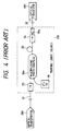
- Fig. 4 is a schematic diagram of a basic configuration of an optical fiber amplifier using an Er-added optical fiber.
- the optical fiber amplifier 210 (surrounded by the dotted line in Fig. 4) comprises an optical fiber 31 having an input terminal connected to an optical transmitter 200, an optical fiber 32 having an output terminal connected to an optical receiver 202, and an Er-added optical fiber 35 coupled between the optical fibers 31 and 32 through optical isolators 33 and 34.
- An pumping light source 36 is coupled with the Er-added optical fiber 35 through a multiplexing photo-coupler 36a.
- a filter 35a is inserted between the optical isolator 34 and optical fiber 32.
- Optical isolators 33 and 34 are non-reciprocal optical elements which transmit light in one direction only.
- the optical isolators 33 and 34 suppress the laser oscillation of the Er-added optical fiber 35. Therefore, in this system, all light signals are prevented from propagating to the transmitter from the receiver by the optical isolator 33 or 34.
- OTDR optical time domain reflectometer
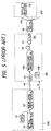
- Figure 5 is a schematic diagram of an example of an optical communication system using an optical fiber amplifier comprising an Er-added fiber.
- An optical signal is transmitted from a center office 400 via an optical fiber amplifier 410 to a subscriber 420.
- An OTDR 41 and an optical transmitter 42 are provided in the center office 400.
- the OTDR 41 and the optical transmitter 42 are connected to an optical fiber 44 through a common multiplexing photo-coupler 43.
- the optical fiber 44 acts as a transmission line and is connected to an Er-added optical fibers 46 through an optical isolator 45, and the end terminal of the Er-added optical fiber 46 is connected to an input port of a star coupler 48 through an optical isolator 47.
- An output port of the star coupler 48 is connected to a plurality of optical fibers 49a which are each connected to a receiver 49.
- the optical isolator 45 is connected to the Er-added optical fiber 46 through a multiplexing photo-coupler 46a which is adapted to inject pumping laser light provided by a semiconductor laser 46b to the Er-added optical fiber 46.
- a filter 46c is inserted after the optical isolator 47 and the star coupler 48.
- An optical signal transmitted from the center office 400 is amplified by the Er-added optical fiber 46 excited by a semiconductor laser of the 1.48 ⁇ m band, and then propagates to the each receiver 49 through the star coupler 48 and optical fiber 49a. Then, by using the OTDR 41 mounted with a semiconductor laser, for example, of the 1.31 ⁇ m band range, it is possible to monitor the conditions of the optical fiber 44 at the center office 400.
- the optical isolators are inserted to the optical transmission line constituted by the optical fiber 44, the Er-added optical fiber 46 and the star coupler 48, it is impossible to transmit a optical signal from a receiver 49 to the center office 400.
- the region capable of being monitored by the OTDR 41 is limited to the section A from the center office 400 to the optical isolator 45.
- Document EP-A-0 445 364 which represents a prior art document according to Article 54(3) EPC discloses an optical communication system with a wavelength multiplex means and an optical amplifier wherein wavelength selective couplers are disposed at each end of the amplifier. Signals with the operation wavelength are supplied to the amplifier over first terminals of the couplers while signals with the second wavelength travel along a bypass connection between second terminates of the couplers.
- the coupler for optical communication of document JP-A-59-91745 is provided with a bypass circuit between branches of two directional couplers and with photoelectric and electrooptic converters between other branches. Thereby, it is possible to dispose an amplifier between the photoelectric converters. It is not known from this reference to monitor the conditions in the entire optical coupler in particular in the optical amplifier.
- an optical communication system comprising the features of claim 1.
- Advantageous embodiments of the invention are defined in the dependent claims.
- a novel configuration of an optical communication system is proposed which comprises an optical fiber line coupled to an optical fiber amplifier such as an Er-added optical fiber or the like, and an optical transmission line to by-pass the optical fiber amplifier to provide bi-directional transmission and to allow back scattering light to propagate towards a transmitter.
- the optical communication system uses the optical fiber as a optical signal transmission line.
- the optical fiber line includes a two-piece trunk line optical fiber with each piece having first and second terminals. One terminal of the first piece is coupled to a center office.
- the optical fiber amplifier has first and second terminals with an optical isolator coupled to each terminal.
- the second terminal of the first piece of the trunk line optical fiber is coupled to the optical isolator coupled to the first terminal of the optical fiber amplifier and the first terminal of the second piece of the trunk line optical fiber is coupled to the optical isolator coupled to the second terminal of the optical fiber amplifier.
- the optical communication system further comprises subscriber optical fibers.
- Each subscriber optical fiber has a start terminal coupled with the second terminal of the second piece of the trunk line optical fiber and an end terminal coupled with a respective receiver.
- the by-pass optical transmission line constitutes an optical fiber having first and second terminals.
- the first terminal of the by-pass optical transmission line optical fiber is coupled to both the first piece of the trunk line optical fiber and the optical isolator coupled to the first terminal of the optical fiber amplifier through a first multiplexing/demultiplexing photo-coupler.
- the second terminal of the by-pass light transmission line optical fiber is coupled to both the second piece of the trunk line optical fiber and the optical isolator coupled to the second terminal of the optical fiber amplifier through a second multiplexing/demultiplexing photo-coupler.
- the main feature of the optical communication system according to the present invention is that the by-pass optical transmission line is in parallel to the optical fiber amplifier and thus permits optical signals to propagate from the subscriber back to the center office.
- optical isolators which are non-reciprocal elements have been used to prevent oscillation in the optical fiber amplifier. Therefore, optical signals are prevented from propagating in a direction other than a predetermined transmission direction.
- an optical fiber line bypasses the optical fiber amplifier and the optical isolators disposed at both ends of the optical fiber amplifier. Therefore, an optical signal propagating from the subscriber to the center office travels through this by-pass optical fiber line.
- bi-directional optical signal communication is possible and the OTDR is available to monitor the entire optical fiber line.
- predetermined addresses are assigned to each respective receivers in advance and a call signal is added to a portion of an optical signal transmitted from the center office. Therefore, it is possible to detect when a call signal is issued to the subscribers successfully and if any subsriber has generated no response to the call signal, faults is presumed to exist in the optical fiber line of the subscriber that has not generated a response.
- the pumping light is supplied from the center office by using another optical fiber, it is also possible to monitor the operation conditions of the optical fiber amplifier through this independent optical fiber for pumping. That is, a branching coupler is inserted after the second terminal of the optical fiber amplifier to tap an amplified signal and to return the tapping signal to the center office through the above-mentioned independent optical fiber. Therefore, it is possible to monitor the operation conditions of both the optical fiber amplifier and an optical fiber line used for communication.
- This optical fiber amplifier monitoring can be used not only to detect faults with the optical fiber amplifier but also to stabilize the signal quality or signal level propagating to a subsriber.
- the optical fiber line and optical fiber amplifier are made up of passive elements, the system is easily built and maintained and is highly reliable.
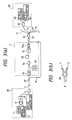
- Fig. 1(a) is a schematic diagram of the basic configuration of the optical communication system according to the present invention.
- this optical communication system includes an OTDR 1, an optical receiver 2 and an optical transmitter 3 collectively grouped as a center office 20.
- the optical transmitter 3 is further coupled to a multiplexing/demultiplexing photo-coupler 4.
- the OTDR 1 and the optical receiver 2 are selectively coupled to the multiplexing/demultiplexing photo-coupler 4 through the optical switch 6.
- a trunk line optical fiber 5 has first and second pieces, each having first and second terminals, and the multiplexing/demultiplexing photo-coupler 4 is coupled to the first terminal of the first piece of the trunk optical fiber 5.
- An optical fiber amplifier 7 comprises an Er-added optical fiber 73 having first and second terminals.
- Optical isolators 71 and 72 are coupled to the first terminal and second terminal of Er-added optical fiber 73, respectively.
- a semiconductor laser 75 coupled to the Er-added optical fiber 73 through a multiplexing photo-coupler 74, injects pumping light into the Er-added optical fiber 73.
- the optical isolator 71 is coupled to the second terminal of the first piece of the trunk line optical fiber 5.
- a filter 73a is coupled to the optical isolator 72 and first terminal of the second piece of the trunk line optical fiber 5.
- By-pass optical fiber 8 has first and second terminals and multiplexing/demultiplexing photo-coupler 9 couples the first terminal of by-pass optical fiber 8 to the second terminal of the first piece of trunk line optical fiber 5 and the optical isolator 71.
- Optical fibers for subscriber 11 each comprise first and second terminals.
- a first terminal of each optical fiber 11 is coupled to the second terminal of the second piece of the trunk line optical fiber 5 and to the second terminal of by-pass optical fiber 8 through a star coupler 10.
- Optical receivers 13 and optical transmitters 14 are provided for each subscriber 30 such that one optical receiver 13 and one optical transmitter 14 are coupled through a multiplexing/demultiplexing photo-coupler 12 to a second terminal of each optical fiber 11.
- the branching ratio has low dependency on wavelength.
- the optical switch 6 is switched to permit signal transmission from the optical transmitter 3.
- a optical signal for example, may have a wavelength of 1.55 ⁇ m.
- An optical signal sent out from the optical transmitter 3 propagates to a subscriber 30 through the multiplexing/demultiplexing photo-coupler 4, the trunk line optical fiber 5, the optical fiber amplifier 7, the star coupler 10 and the receiver station optical fiber for subscribers 11. In the subscriber 30, this optical signal is received by an optical receiver 13 through the multiplexing/demultiplexing photo-coupler 12.
- an optical signal having a wavelength of 1.31 ⁇ m can be transmitted from the optical transmitter 14 of the subscriber 30 to the center office 20 through the optical fiber for subscriber 11, the star coupler 10, the by-pass optical fiber 8, the multiplexing photo-coupler 9, the trunk line optical fiber 5 and the multiplexing/demultiplexing photo-coupler 4.
- this optical signal is received by the optical receiver 2.
- the optical switch 6 is switched to the OTDR 1.
- Fig. 1(b) is a schematic diagram of an alternative embodiment of center office 20. Parts being the same as those in Fig. 1(a) are referenced correspondingly.
- the OTDR 1 is coupled to the optical switch 6 through a selection optical switch 1a.
- the selection optical switch 1a selectively couples OTDR 1 to the optical switch 6 and to terminals 1b. Therefore, the OTDR 1 can be connected to the optical switch by the selection optical switch 1a only when the OTDR 1 is used by the optical communication system shown in Fig. 1(a). Otherwise, by switching the selection optical switch 1a, the OTDR 1 can be used by other equipment (not shown) connected to the selection light switch 1a at terminals 1b.
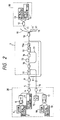
- Fig. 2 is a schematic diagram of an alternative embodiment of a high-functional optical communication system according to the invention. Parts being the same as those in the optical communication system shown in Fig. 1(a) are referenced correspondingly.
- the center office 20 is provided with an OTDR 18 and a optical receiver 19 coupled to a optical switch 17, and a semiconductor laser 75 for supplying pumping light to an optical fiber amplifier 7.
- An optical fiber 16 is provided having first and second terminals.
- the optical switch 17 and the semiconductor laser 75 are coupled to the first terminal of optical fiber 16 through multiplexing/demultipexing photo-coupler 15.
- the second terminal of the optical fiber 16 is coupled to the Er-added optical fiber 73 and the optical isolator 71 by photo-coupler 74.
- tapped signal from the output of the optical fiber amplifier by inserting a branching photo coupler 76 between the Er-added optical fiber 73 and the optical isolator 72 is coupled to branch optical fiber 77, and provided to the second terminal of the optical fiber for supplying pumping light 16 through the photo-coupler 74. This arrangement permits the tapped signal to return to the center office 20 through the optical fiber for supplying pumping light 16.
- OTDR 1 monitors the conditions of the optical fiber as described for the Fig. 1(a) embodiment
- the Fig. 2 embodiment also enables the operation conditions, the fault production, etc. of the optical fiber amplifier 7 to be monitored at the center office 20 through the optical fiber for supplying pumping light 16 as follows.
- the optical fiber amplifier 7 a portion of an optical signal amplified by an Er-added optical fiber 73, for example, 1/100 of the optical signal, is removed by the branching photo-coupler 76 and provided to the optical fiber 16 through branch optical fiber 77 and photo-coupler 74. Therefore, by switching the optical switch 17 to access the optical receiver 19, it is possible to monitor, at the center office 20, the conditions of the optical signal which has been amplified by the optical fiber amplifier 7. If the output is decreased due to disconnection, breakage of an optical fiber, or the like in the optical fiber amplifier 7, these conditions can be detected at the center office 20. In addition, by chenging a driving current for the semiconductor laser 75, the amount of pumping light provided can be controlled and therefore the receiving level of the optical receiver 19 is kept constant. This permits AGC (Automatic Gain Control) of the optical fiber amplifier 7.
- AGC Automatic Gain Control
- a decrease in the output power of the optical fiber amplifier 7 also could be due to degradations in the semiconductor laser 75.
- the output power of the semiconductor laser 75 can be monitored by a photodiode included in the semiconductor laser nudule.
- the conditions of the optical fiber for suppleying pumping light 16 can be monitored through the OTDR 18 by switching the optical switch 17 to access the OTDR 18.
- the operation of the optical transmitter 3 in the center office 20 also can be monitored by a photodiode disposed in the optical transmitter 3.
- photo-couplers 4, 9, 10, 12, 15, 74 and 76, trunk line optical fiber 5, optical fiber for supplying pumping light 16, optical isolators 71 and 72, Er-added optical fiber 73, filter 73a, and receiver station optical fiber for subscriber 11 are passive elements. This provides high reliability and easy maintenance becouse all components in the field are passive.
- each subscriber 30 is given its own address in advance, and a optical signal including a call signal is transmitted from the center office 20 to each of the respective subscribers 30 sequentially.
- a optical transmitter 14 in each subscriber 30 transmits a predetermined signal in to call from the center office 20, and the optical receiver 2 in the center office 20 receives the predetermined signals from the subscribers 30 sequentially. Therefore, if a receiver station 30 gives no response, this indicates that the receiver station optical fiber for subscribers 11 connected to that subscribere is defective.
- the above wavelengths are merely examples of possible wavelengths that can be used.
- the optical signal wavelengths used by the OTDRs and the optical signals propagating from the subscriber 30 to the center office 20 are different, it is possible to replace the optical switches provided in the center office 20 with photo-couplers.
- the optical fiber amplifier 7 may comprise an element other than an Er-added optical fiber.
- Fig. 3(a) is a schematic diagram of another embodiment of the optical communication system according to the present invention, which has the same basic configuration and system functions as the optical communication system shown in Fig. 1(a). Parts being the same as those in the optical communication system shown in Fig. 1(a) are referenced correspondingly.
- This embodiment differs from the Embodiment in Fig. 1(a) such that trunk line optical fiber 5 is coupled to the by-pass optical fiber 8 by optical circulators 21 and 22.
- the first terminal of the bypass optical fiber 8 is coupled with the trunk line optical fiber 5 by the optical circulator 21 and not by a multiplexing photo-coupler (the multiplexing photocoupler 9 in the optical communication system shown in Fig. 1(a)).
- the second terminal of the by-pass optical fiber 8 is coupled with the trunk line optical fiber 5 by the optical circulator 22 and not by the star coupler 10.
- Fig. 3(b) is a schematic diagram which explains the function of a optical circulator used as a multiplexing/demultiplexing photo-coupler in the optical communication system of this embodiment.
- An optical circulator 20 has three or more input/output ports X, Y and Z, and couples an optical signal injected from a certain port with a adjacent port on a certain side. That is, the following coupling is realized by this example.
- port X ⁇ port Y port Y ⁇ port Z port Z ⁇ port X Details of an optical circulator are described in Chapter 10, etc., of "Optical Integrated Circuit", edited by The Japan Society of Applied Physics/Optics Social Meeting, published by Asakura Shoten.
- an optical signal transmitted from the optical transmitter 3 of the center office 20 is coupled with only the optical fiber amplifier 7 by the optical circulator 21 and is not coupled with the by-pass optical fiber 8.
- an optical signal transmitted from the subscriber 30 or back scattering light is coupled with only the by-pass optical fiber 8 by the optical circulator 22 and is not transmitted to the optical fiber amplifier 7.
- the present invention demonstrates that bi-directional optical signal transmission can be achieved in an optical transmission line which uses an optical fiber amplifier having optical isolators.
- the present invention can be applied not only to an optical communication system using an optical fiber amplifier but also to an optical communication system comprising, for example, a semiconductor laser amplifier including optical isolators.
Landscapes
- Engineering & Computer Science (AREA)
- Physics & Mathematics (AREA)
- Electromagnetism (AREA)
- Computer Networks & Wireless Communication (AREA)
- Signal Processing (AREA)
- Computing Systems (AREA)
- Optical Communication System (AREA)
- Light Guides In General And Applications Therefor (AREA)
- Lasers (AREA)
Claims (7)
- Ein optisches Kommunikationssystem, umfassend:eine erste optische Fasereinrichtung (5) zum Übertragen optischer Signale in einer ersten Richtung, wobei die genannte erste, optische Fasereinrichtung aus Teilen besteht, wobei jedes der genannten Teile ein erstes und ein zweites Ende hat;eine Einrichtung (7), die mit dem genannten zweiten Ende des genannten ersten Teils der genannten ersten, optischen Fasereinrichtung (5) und mit dem genannten ersten Ende eines zweiten Teils der genannten ersten, optischen Fasereinrichtung (5) gekoppelt ist, um die genannten optischen Signale zu verstärken, die in der genannten ersten Richtung übertragen werden;eine Einrichtung (4, 20), die mit dem genannten ersten Ende des genannten ersten Teils der genannten ersten, optischen Fasereinrichtung (5) gekoppelt ist, um die genannten optischen Signale, die in der genannten ersten Richtung übertragen werden, der genannten ersten, optischen Fasereinrichtung (5) zu liefern;eine Einrichtung (13, 30), die mit dem genannten zweiten Ende des genannten zweiten Teils der genannten ersten, optischen Fasereinrichtung (5) gekoppelt ist, um die genannten optischen Signale zu empfangen, die in der genannten ersten Richtung übertragen werden; undeine erste Einrichtung (1) zum Überwachen von Zuständen der genannten ersten, optischen Fasereinrichtung (5), dadurch gekennzeichnet, daß es des weiteren umfaßteine zweite, optische Fasereinrichtung (8) zum Übertragen der genannten optischen Signale in einer zweiten Richtung, wobei die genannte zweite Richtung im wesentlichen zu der genannten ersten Richtung entgegengesetzt ist, die genannte zweite, optische Fasereinrichtung (8) ein erstes Ende mit dem genannten ersten Teil der genannten ersten, optischen Fasereinrichtung (5) gekoppelt hat und ein zweites Ende mit dem genannten zweiten Teil der genannten erste, optischen Fasereinrichtung (5) gekoppelt hat, wobei die genannte zweite, optische Fasereinrichtung (8) die genannte Verstärkungseinrichtung (7) umgeht;eine dritte, optische Fasereinrichtung (16), die ein erstes und ein zweites Ende aufweist, um eine Einrichtung zum Einspeisen von Pumplicht (75) in eine verstärkende, optische Faser (73) in der genannten Verstärkereinrichtung (7) zu koppeln, wobei das genannte erste Ende der genannten dritten, optischen Faser (16) mit der genannten Einspeisungseinrichtung (75) gekoppelt ist und das genannte zweite Ende der genannten dritten, optischen Faser (16) mit der genannten verstärkenden, optischen Faser (73) gekoppelt ist;eine zweite Einrichtung (18) zum Überwachen von Zuständen der genannten dritten, optischen Faser (16);eine erste Empfangseinrichtung (19) zum Empfangen optischer Signale, die von der genannten Verstärkungseinrichtung (7) verstärkt worden sind, und zum Überwachen von Betriebsbedingungen der genannten Verstärkungseinrichtung nach Maßgabe der genannten verstärkten, optischen Signale; undeine erste Schaltereinrichtung (17) zum selektiven Koppeln der genannten zweiten Überwachungseinrichtung (18) und der genannten zweiten Empfangseinrichtung (19) mit dem genannten ersten Ende der genannten dritten, optischen Faser (16); unddaß die genannte erste Überwachungseinrichtung (1) auch die Zustände der genannten zweiten, optischen Fasereinrichtung (8) überwacht.
- Ein optisches Kommunikationssystem wie in Anspruch 1, worindie genannte verstärkende, optische Faser eine optische Faser (73) mit Er-Zusatz ist;die genannte Einspeisungseinrichtung für Pumplicht ein Halbleiterlaser (75) zum Einspeisen von Pumplicht in die genannte optische Faser mit Er-Zusatz ist; unddie genannte Verstärkungseinrichtung (7) ferner umfaßt:eine Photokopplereinrichtung (74) zum Koppeln des genannten Halbleiterlasers mit der genannten optischen Faser mit Er-Zusatz; undzwei optische Richtleiter (71, 72), wobei jede der genannten optischen Richtleiter an entgegengesetzten Enden der genannten Verstärkungseinrichtung (7) angeordnet ist, einer der genannten optischen Richtleiter (71) mit der genannten Photokopplereinrichtung gekoppelt ist und ein zweiter der genannten optischen Richtleiter (72) mit der genannten optischen Faser mit Er-Zusatz gekoppelt ist.
- Ein optisches Kommunikationssystem, wie in Anspruch 1 oder 2, worin die genannte optische Signalbereitstellungseinrichtung umfaßt:eine Photokopplereinrichtung (4) zum Koppeln der genannten optischen Signalbereitstellungseinrichtung mit dem genannten ersten Ende des genannten ersten Teils der genannten ersten, optischen Fasereinrichtung (5);eine zweite Lichtempfangseinrichtung (2) zum Empfangen der genannten optischen Signale, die in der genannten zweiten Richtung übertragen werden;eine zweite Schaltereinrichtung (6) zum selektiven Koppeln der genannten Überwachungseinrichtung (1) und der genannten ersten Lichtempfangseinrichtung (2) mit dem genannten zweiten Photokoppler (4); undeine optische Signalerzeugungseinrichtung (3), die mit der genannten zweiten Photokopplereinrichtung (4) gekoppelt ist, um die genannten optischen Signale dem genannten ersten Ende des genannten ersten Teils der genannten ersten, optischen Fasereinrichtung (5) zuzuführen.
- Ein optisches Kommunikationssystem, wie in Anspruch 1, das ferner eine oder mehrere Bestimmungseinrichtungen (11) umfaßt, von denen jede umfaßt:eine optische Faserkopplungseinrichtung (10) zum Koppeln der genannten Bestimmungseinrichtung mit dem genannten zweiten Ende des genannten zweiten Teils der genannten erste, optischen Fasereinrichtung (5);eine Einrichtung (13) zum Empfangen der genannten Lichtsignale, die in der genannten ersten Richtung übertragen werden;eine Einrichtung (14) zum Bereitstellen der genannten Lichtsignale, die in der genannten zweiten Richtung übertragen werden, für die genannte zweite, optische Fasereinrichtung (8); undeine Photokopplereinrichtung (12) zum Koppeln der genannten Empfangseinrichtung (13) und der genannten Lichtsignalerzeugungseinrichtung (14) mit der genannten optischen Faserkopplungseinrichtung (10).
- Ein optisches Kommunikationssystem, wie in Anspruch 1, das ferner umfaßt:eine Photokopplereinrichtung (9) zum Koppeln des genannten ersten Teils der genannten ersten, optischen Fasereinrichtung (5) mit dem genannten ersten Ende der genannten zweiten, optischen Fasereinrichtung (8); undeine zweite Photokopplereinrichtung (10) zum Koppeln des genannten zweiten Endes des genannten zweiten Teils der genannten ersten, optischen Fasereinrichtung (5) mit der genannten wenigstens einen der genannten Bestimmungseinrichtungen (11).
- Ein optisches Kommunikationssystem, wie in Anspruch 3, worin die genannte optische Signalbereitstellungseinrichtung (20) des weiteren eine dritte Schaltereinrichtung (la) umfaßt, die zwischen der genannten Überwachungseinrichtung (1) und der genannten zweiten Schaltereinrichtung (6) zum selektiven Koppeln der genannten Überwachungseinrichtung (1) mit einem einer Mehrzahl von Verbindungsanschlüssen (1b) gekoppelt ist.
- Ein optisches Kommunikationssystem, wie in Anspruch 1, ferner umfassend:eine erste optische Richtungsgabel (21) zum Koppeln des genannten ersten Endes der genannten zweiten, optischen Fasereinrichtung (8) mit dem genannten ersten Teil der genannten ersten, optischen Fasereinrichtung (5), undeine zweite optische Richtungsgabel (22) zum Koppeln des genannten zweiten Endes der genannten zweiten, optischen Fasereinrichtung (8) mit dem genannten zweiten Teil der genannten ersten, optischen Fasereinrichtung (5).
Applications Claiming Priority (2)
| Application Number | Priority Date | Filing Date | Title |
|---|---|---|---|
| JP161077/90 | 1990-06-19 | ||
| JP02161077A JP3100386B2 (ja) | 1990-06-19 | 1990-06-19 | 光通信システム |
Publications (2)
| Publication Number | Publication Date |
|---|---|
| EP0467080A1 EP0467080A1 (de) | 1992-01-22 |
| EP0467080B1 true EP0467080B1 (de) | 1997-03-12 |
Family
ID=15728191
Family Applications (1)
| Application Number | Title | Priority Date | Filing Date |
|---|---|---|---|
| EP91109963A Expired - Lifetime EP0467080B1 (de) | 1990-06-19 | 1991-06-18 | Lichtübertragungssystem |
Country Status (7)
| Country | Link |
|---|---|
| EP (1) | EP0467080B1 (de) |
| JP (1) | JP3100386B2 (de) |
| AU (1) | AU632697B2 (de) |
| CA (1) | CA2044919C (de) |
| DE (1) | DE69125065T2 (de) |
| FI (1) | FI103236B (de) |
| NO (1) | NO308499B1 (de) |
Families Citing this family (11)
| Publication number | Priority date | Publication date | Assignee | Title |
|---|---|---|---|---|
| GB9022681D0 (en) * | 1990-10-18 | 1990-11-28 | British Telecomm | Passive optical network |
| DE69228087T2 (de) * | 1991-05-27 | 1999-08-05 | The Furukawa Electric Co., Ltd., Tokio/Tokyo | Optischer Verstärker |
| IT1279126B1 (it) * | 1995-04-18 | 1997-12-04 | Sip | Amplificatore ottico bidirezionale a fibra attiva. |
| GB9526176D0 (en) * | 1995-12-21 | 1996-02-21 | Stc Submarine Systems Ltd | System fibre break detection in systems using ropas |
| JPH09261187A (ja) * | 1996-03-19 | 1997-10-03 | Fujitsu Ltd | 無中継光伝送システムのリモートアンプおよび障害点標定方法 |
| JP3107033B2 (ja) * | 1998-03-09 | 2000-11-06 | 日本電気株式会社 | 光増幅装置とこれを含む光伝送装置の伝送路破断点検出方法および光増幅装置を用いた双方向波長多重光伝送装置 |
| US9410866B2 (en) | 2012-08-29 | 2016-08-09 | Telefonaktiebolaget L M Ericsson (Publ) | Device for monitoring an optical fibre |
| BR112013023723A2 (pt) * | 2013-03-05 | 2016-12-13 | Ericsson Telecomunicações S A | disposição de amplificador óptico |
| EP2819321A1 (de) * | 2013-06-27 | 2014-12-31 | Alcatel Lucent | Paketoptischer Add-Drop-Multiplex-Knoten für ein optisches Ringnetzwerk |
| JP7424391B2 (ja) * | 2019-12-04 | 2024-01-30 | 日本電気株式会社 | 光ファイバセンシングシステム、中継装置及びセンシング方法 |
| JPWO2024214272A1 (de) * | 2023-04-14 | 2024-10-17 |
Family Cites Families (5)
| Publication number | Priority date | Publication date | Assignee | Title |
|---|---|---|---|---|
| JPS581859B2 (ja) * | 1975-02-14 | 1983-01-13 | 株式会社日立製作所 | ヒカリチユウケイキ |
| JPS56140257U (de) * | 1980-03-24 | 1981-10-23 | ||
| JPS5991745A (ja) * | 1982-11-18 | 1984-05-26 | Yamatake Honeywell Co Ltd | 光通信用結合装置 |
| JPS59188249A (ja) * | 1984-03-22 | 1984-10-25 | Hitachi Ltd | 光中継増幅器 |
| JPH021631A (ja) * | 1988-06-09 | 1990-01-05 | Fujitsu Ltd | 光ケーブル通信方式 |
-
1990
- 1990-06-19 JP JP02161077A patent/JP3100386B2/ja not_active Expired - Lifetime
-
1991
- 1991-06-17 NO NO912327A patent/NO308499B1/no not_active IP Right Cessation
- 1991-06-18 AU AU78488/91A patent/AU632697B2/en not_active Ceased
- 1991-06-18 CA CA002044919A patent/CA2044919C/en not_active Expired - Fee Related
- 1991-06-18 DE DE69125065T patent/DE69125065T2/de not_active Expired - Fee Related
- 1991-06-18 FI FI912962A patent/FI103236B/fi active
- 1991-06-18 EP EP91109963A patent/EP0467080B1/de not_active Expired - Lifetime
Also Published As
| Publication number | Publication date |
|---|---|
| FI103236B1 (fi) | 1999-05-14 |
| EP0467080A1 (de) | 1992-01-22 |
| NO912327L (no) | 1991-12-20 |
| AU632697B2 (en) | 1993-01-07 |
| CA2044919C (en) | 1996-06-11 |
| FI912962A7 (fi) | 1991-12-20 |
| AU7848891A (en) | 1992-01-02 |
| DE69125065D1 (de) | 1997-04-17 |
| NO308499B1 (no) | 2000-09-18 |
| JPH0451620A (ja) | 1992-02-20 |
| CA2044919A1 (en) | 1991-12-20 |
| FI912962A0 (fi) | 1991-06-18 |
| DE69125065T2 (de) | 1997-06-19 |
| FI103236B (fi) | 1999-05-14 |
| NO912327D0 (no) | 1991-06-17 |
| JP3100386B2 (ja) | 2000-10-16 |
Similar Documents
| Publication | Publication Date | Title |
|---|---|---|
| US5214728A (en) | Light communication system | |
| CA2014551C (en) | Optical branching equipment and optical network using the same | |
| CA2093259C (en) | Frequency dependent optical isolator | |
| EP0847158A2 (de) | Vorrichtung zum optischen Wellenlängen-Multiplexen und Demultiplexen und optisches Nachrichtenübertragungssystem, das diese verwendet | |
| US4899043A (en) | Fault monitoring system for optical fiber communication systems | |
| US6580530B1 (en) | Optical communication system | |
| JPH0637717A (ja) | 光中継器の監視制御方式 | |
| JPH08204636A (ja) | 光通信システム | |
| EP0467080B1 (de) | Lichtübertragungssystem | |
| WO1997012265A2 (en) | Optical amplifier internal input monitoring signal tap | |
| EP0506753B1 (de) | Verlustfreie optische komponente | |
| CA2174286A1 (en) | Bidirectional optical amplifier using an active fibre | |
| WO1995015625A1 (en) | Bidirectional optical amplifier | |
| US6809846B2 (en) | Optical switch and optical network | |
| EP0982881B1 (de) | Optischer Verstärker, Übertragungsgerät, Übertragungssystem und Verfahren | |
| JP2714611B2 (ja) | 光中継器及びそれを使った光伝送路網 | |
| Chen et al. | Demonstration of in-service supervisory repeaterless bidirectional wavelength-division-multiplexing transmission system | |
| JP3557025B2 (ja) | 方向切替型光増幅器と同増幅器を用いたバス型一芯光通信システム | |
| JPH039625A (ja) | 光通信システムの障害監視方式 | |
| JP2732746B2 (ja) | 光増幅器の入出力光パワーのモニタ方法 | |
| US6023543A (en) | Bidirectional optical link, and device for amplifying such link | |
| JPH02281831A (ja) | 光シャットダウン方式 | |
| JP3260839B2 (ja) | 光増幅器 | |
| JPH05284114A (ja) | 光中継器監視装置 | |
| JPH09116494A (ja) | 波長分割多重海底分岐方式 |
Legal Events
| Date | Code | Title | Description |
|---|---|---|---|
| PUAI | Public reference made under article 153(3) epc to a published international application that has entered the european phase |
Free format text: ORIGINAL CODE: 0009012 |
|
| AK | Designated contracting states |
Kind code of ref document: A1 Designated state(s): BE DE FR GB IT NL |
|
| 17P | Request for examination filed |
Effective date: 19920316 |
|
| 17Q | First examination report despatched |
Effective date: 19940208 |
|
| GRAG | Despatch of communication of intention to grant |
Free format text: ORIGINAL CODE: EPIDOS AGRA |
|
| GRAH | Despatch of communication of intention to grant a patent |
Free format text: ORIGINAL CODE: EPIDOS IGRA |
|
| GRAH | Despatch of communication of intention to grant a patent |
Free format text: ORIGINAL CODE: EPIDOS IGRA |
|
| GRAA | (expected) grant |
Free format text: ORIGINAL CODE: 0009210 |
|
| AK | Designated contracting states |
Kind code of ref document: B1 Designated state(s): BE DE FR GB IT NL |
|
| REF | Corresponds to: |
Ref document number: 69125065 Country of ref document: DE Date of ref document: 19970417 |
|
| ITF | It: translation for a ep patent filed | ||
| ET | Fr: translation filed | ||
| PLBE | No opposition filed within time limit |
Free format text: ORIGINAL CODE: 0009261 |
|
| STAA | Information on the status of an ep patent application or granted ep patent |
Free format text: STATUS: NO OPPOSITION FILED WITHIN TIME LIMIT |
|
| 26N | No opposition filed | ||
| PGFP | Annual fee paid to national office [announced via postgrant information from national office to epo] |
Ref country code: FR Payment date: 20010611 Year of fee payment: 11 Ref country code: DE Payment date: 20010611 Year of fee payment: 11 |
|
| PGFP | Annual fee paid to national office [announced via postgrant information from national office to epo] |
Ref country code: GB Payment date: 20010613 Year of fee payment: 11 |
|
| PGFP | Annual fee paid to national office [announced via postgrant information from national office to epo] |
Ref country code: NL Payment date: 20010628 Year of fee payment: 11 |
|
| PGFP | Annual fee paid to national office [announced via postgrant information from national office to epo] |
Ref country code: BE Payment date: 20010816 Year of fee payment: 11 |
|
| REG | Reference to a national code |
Ref country code: GB Ref legal event code: IF02 |
|
| PG25 | Lapsed in a contracting state [announced via postgrant information from national office to epo] |
Ref country code: GB Free format text: LAPSE BECAUSE OF NON-PAYMENT OF DUE FEES Effective date: 20020618 |
|
| PG25 | Lapsed in a contracting state [announced via postgrant information from national office to epo] |
Ref country code: BE Free format text: LAPSE BECAUSE OF NON-PAYMENT OF DUE FEES Effective date: 20020630 |
|
| BERE | Be: lapsed |
Owner name: *NIPPON TELEGRAPH AND TELEPHONE CORP. Effective date: 20020630 Owner name: *SUMITOMO ELECTRIC INDUSTRIES LTD Effective date: 20020630 |
|
| PG25 | Lapsed in a contracting state [announced via postgrant information from national office to epo] |
Ref country code: NL Free format text: LAPSE BECAUSE OF NON-PAYMENT OF DUE FEES Effective date: 20030101 Ref country code: DE Free format text: LAPSE BECAUSE OF NON-PAYMENT OF DUE FEES Effective date: 20030101 |
|
| GBPC | Gb: european patent ceased through non-payment of renewal fee |
Effective date: 20020618 |
|
| PG25 | Lapsed in a contracting state [announced via postgrant information from national office to epo] |
Ref country code: FR Free format text: LAPSE BECAUSE OF NON-PAYMENT OF DUE FEES Effective date: 20030228 |
|
| NLV4 | Nl: lapsed or anulled due to non-payment of the annual fee |
Effective date: 20030101 |
|
| REG | Reference to a national code |
Ref country code: FR Ref legal event code: ST |
|
| PG25 | Lapsed in a contracting state [announced via postgrant information from national office to epo] |
Ref country code: IT Free format text: LAPSE BECAUSE OF NON-PAYMENT OF DUE FEES;WARNING: LAPSES OF ITALIAN PATENTS WITH EFFECTIVE DATE BEFORE 2007 MAY HAVE OCCURRED AT ANY TIME BEFORE 2007. THE CORRECT EFFECTIVE DATE MAY BE DIFFERENT FROM THE ONE RECORDED. Effective date: 20050618 |