EP0467209A2 - Compteur de distance - Google Patents
Compteur de distance Download PDFInfo
- Publication number
- EP0467209A2 EP0467209A2 EP91111479A EP91111479A EP0467209A2 EP 0467209 A2 EP0467209 A2 EP 0467209A2 EP 91111479 A EP91111479 A EP 91111479A EP 91111479 A EP91111479 A EP 91111479A EP 0467209 A2 EP0467209 A2 EP 0467209A2
- Authority
- EP
- European Patent Office
- Prior art keywords
- fare
- display
- distance
- odometer
- route
- Prior art date
- Legal status (The legal status is an assumption and is not a legal conclusion. Google has not performed a legal analysis and makes no representation as to the accuracy of the status listed.)
- Withdrawn
Links
- 230000001960 triggered effect Effects 0.000 claims abstract description 7
- 238000001514 detection method Methods 0.000 claims description 7
- 230000004913 activation Effects 0.000 claims description 3
- 230000003068 static effect Effects 0.000 claims description 2
- 238000006243 chemical reaction Methods 0.000 description 2
- 239000004973 liquid crystal related substance Substances 0.000 description 2
- 238000000034 method Methods 0.000 description 2
- 238000000926 separation method Methods 0.000 description 2
- 230000003213 activating effect Effects 0.000 description 1
- 239000000654 additive Substances 0.000 description 1
- 230000000996 additive effect Effects 0.000 description 1
- 230000005540 biological transmission Effects 0.000 description 1
- 238000010586 diagram Methods 0.000 description 1
- 238000011156 evaluation Methods 0.000 description 1
- 238000007689 inspection Methods 0.000 description 1
- 230000011664 signaling Effects 0.000 description 1
Images

Classifications
-
- G—PHYSICS
- G07—CHECKING-DEVICES
- G07B—TICKET-ISSUING APPARATUS; FARE-REGISTERING APPARATUS; FRANKING APPARATUS
- G07B13/00—Taximeters
- G07B13/02—Details; Accessories
-
- G—PHYSICS
- G01—MEASURING; TESTING
- G01C—MEASURING DISTANCES, LEVELS OR BEARINGS; SURVEYING; NAVIGATION; GYROSCOPIC INSTRUMENTS; PHOTOGRAMMETRY OR VIDEOGRAMMETRY
- G01C22/00—Measuring distance traversed on the ground by vehicles, persons, animals or other moving solid bodies, e.g. using odometers, using pedometers
- G01C22/02—Measuring distance traversed on the ground by vehicles, persons, animals or other moving solid bodies, e.g. using odometers, using pedometers by conversion into electric waveforms and subsequent integration, e.g. using tachometer generator
Definitions
- the invention relates to an odometer for the purpose of displaying a distance traveled in a rental car with a driver.
- the vehicles are equipped with a calibrated odometer.
- the device which can be switched on by the driver by means of an operating process by operating a switch, shows on a multi-digit counter the total distance traveled from the start of the service trip.
- a table is available to the driver for converting the distance traveled, from which the driver determines the ticket price to which he is entitled, taking into account additional influencing factors. It is therefore up to the driver to select and apply the "right tariff" from the table when converting it into a fare.
- the table also contains tariffs that include factors that increase the fare and, if used incorrectly, only give the customer an increased fare. Influencing factors that increase the fare are e.g. B. journeys on Sundays and public holidays, at night and the like, where an increase in the service amounts seems justified. However, higher tariffs should only be used for the special shifts provided. Such disadvantages due to incorrect handling must be avoided.
- a direct i.e. H. an immediate running display of a fare instead of the previous distance display at the distance counter of the type mentioned at the beginning is not permitted.
- the immediate display of fare amounts is reserved for the device training of a taximeter for a mode of operation in the taxi vehicle area.
- the object of the invention is to avoid the stated disadvantages and to design a distance counter of the type described in the introduction in such a way that a fare determination and display can be triggered on request in addition to the usual distance display.
- the solution for a distance counter of the type explained at the outset is characterized by a continuous display of the distance traveled in the operational mode of the rental car and a simultaneous internal calculation of a fare based on a permanent registration of distance and waiting time elements.
- the solution described in the exemplary embodiment provides that the previous odometer is expanded in such a way that an internal calculation of a fare takes place in parallel to the function of the odometer display, with little expenditure on circuit and control means. Due to the amount of travel distance constantly displayed while driving and the practically "in the background", i.e. H. unnoticed from the outside, the fare that can be determined from route and waiting time elements can thus comply with the approval regulations. With the mode of internal price calculation using fixed parameters that runs parallel to the route display, the cumbersome and time-consuming determination of the fare using a price table is no longer necessary. In addition, any attempt at fraudulent use of the fare table is prevented. By completely eliminating the price table, any attempt at manipulation in determining the fare is prevented and replaced by automatic pricing that cannot be influenced by the driver.
- the illustration shown in FIG. 1 shows the front of an odometer 1 according to the type described below.
- the odometer 1 is a calibrated device for determining a total distance traveled in a rental vehicle.
- the basis for determining the distance traveled is a pulse generator (not shown in more detail), which provides a certain number of pulses on the input side of the device electronics for each wheel revolution and converts the values using vehicle-specific constants distance traveled shows continuously.
- the conversion of the route impulse sequence into route units, for example of the dimension meters and kilometers, is controlled by a microprocessor and the result is scanned in a display field 2.
- the display field 2 is an LC display module (liquid crystal display) or liquid crystal display module 3, which is designed for scanning a large number of numbers and symbols according to the application.
- the display module 3 is held in a front housing frame 4 of the device.
- the display field 2 has a six-digit main display 5, a four-digit secondary display 6, and a single-digit function level display 7.
- the display elements 5, 6, 7 are 7-segment displays which, by means of appropriate control, represent digits, but which can also display word symbols due to segment combinations which can be controlled as desired.
- six freely parameterizable flags F1 to F6 are provided in display zone 2, which serve, for example, to support the display of special functions in the individual operating states. Under certain operating conditions (for example, when the vehicle speed is below a specified minimum speed), time elements can also be included in the registration of the service.
- a time symbol 8 in the display field 2 signals that time elements are currently flowing into the registry and are included in the overall evaluation at the end of a tour, equivalent to route elements.
- a word symbol "Error” (9) is provided, which indicates a fault and, in conjunction with an assigned code number, localizes the fault.
- this continuously registers the distance traveled in kilometers (kilometers) in the operating mode as a distance counter, for example by additive scanning and display of 100 m route sections in the main display.
- buttons S1, S2, S3, S4 are arranged on the front display and operator side, to which certain key switch functions are assigned depending on the operating state of the device.
- the button switch S1 is used to switch on the device and at the same time to switch on the desired function level and to call up all assigned parameters, starting from the "FREE" operating state indicated in the display field by the flag F3.
- a standard function of the button switch S2 is to activate a display of an internally determined fare parallel to the current route by actuating it when the vehicle is at a standstill, and alternately to display the total fare in the main display 5 by hiding the previously active display of the route traveled.
- buttons S4 and S3 additional amounts (extras) can be opened by repeated actuation, the sum of the selected additional amounts being displayed in the secondary display 6.
- the button switch S3 With a further operation of the button switch S3, the sum of the fare plus surcharges and finally can be shown in the main display 5 when the vehicle is at a standstill.
- the total separation can again be brought about and the partial amounts in the main (5) and secondary displays 6 can be shown separately again.
- a total separation of the type described can also be brought about automatically after a definable or parameterizable time has elapsed.
- the secondary display 6 In addition to the display of surcharges, the secondary display 6 also shows a price / per km during a journey and minutes of waiting time.
- the internally calculated fare during a trip count during a trip is formed below a defined trip speed by gradually increasing the ticket price in definable time intervals and above this set speed by gradually increasing the ticket price in definable trip intervals.
- the internal calculation of the fare is done by adding increment amounts from path and time intervals in the form of a defined overlay of the two interval types.
- the calculation of a fare can trigger a calculation of a basic price, which guarantees the acceptance of a minimum fare.
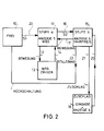
- Function symbol a according to item 11 in the status graph according to FIG. 2 symbolizes the normal operating mode of the distance counter and, during the movement of the vehicle, passes the continuously determined distance for registration via a movement transmission line 12 into the path counter 13. If the vehicle is stopped, a feedback "standstill" is sent to the function stage 11 via a line 14. In this operating state of the vehicle, as already explained, actuation of the button switch S2 can trigger the display of the fare determined up to that point in parallel. On the other hand the state of "standstill" of the vehicle is recognized by a detection device (in FIG.
- the detection device also detects when the vehicle starts moving again from a standstill phase, with the result that a line 17 signaling the movement switches back the static fare display 15 (in FIG. 5) into the running route display 11.
- the operating mode can be selected as a distance counter or as a taximeter, which can be selected using switch-on locks and switch-on releases determined in the control area.
- Activation of the switch-on locks or releases for controlling one or the other operating mode can be achieved by introducing time and / or calendar parameters, by means of which a correspondingly predetermined functional sequence can be controlled automatically in the device.
- a device 18 for entering a surcharge is coupled in connection with the operating mode "display fare" in the functional position 15, such that the surcharge amounts can be entered via the button switch S4 by repeated actuation and can be represented in the secondary display 6 and as such by activating a flag F 6 can be marked.
- the device 18 is connected via a line 20 and a return line 21 to the functional level b or 15 (display 5, fare).
- a display of a route tariff can be triggered, a distinctive arrow or flag F 4 being controllable for distinction, or a corresponding print on a sheet 19 in front of the display module 3 marked.
- the sequence of a travel order is as follows: The distance counter is switched on by pressing the button switch S1 via a switch-on line 23 from a "FREE" position 10 to the functional level a or 11. The distance counter 13 is activated and the result when the vehicle is moving is shown as the distance traveled in the main display 5.
- the fare determined internally "in the background" is increased iteratively according to distance and time intervals.
- the fare includes a basic amount, which is displayed as the minimum fare, and guarantees a minimum income.
- the latter is the case when the distance counter is switched, for example, by the key switch S2 to the billing or functional level b according to item 15, without, for example, a profitable distance-forming route being traveled.
- function stage b or 15 is activated by pressing the key switch S2 via line 16. The fare determined up to that point is hereby displayed in the main display 5. If the journey is continued, the device automatically switches back to functional level a with the current route display in the main display 5, e.g. B. by the detection of a vehicle movement.
- function stage 15 "fare display” is switched manually to the FREE position (10) via a reset line 22 by actuating a key switch S1 or S2.
- a ', a "etc. can be defined in the odometer, which then, for example, only depend on the time / calendar Allow specified function level for activation.
Landscapes
- Physics & Mathematics (AREA)
- General Physics & Mathematics (AREA)
- Engineering & Computer Science (AREA)
- Radar, Positioning & Navigation (AREA)
- Remote Sensing (AREA)
- Devices For Checking Fares Or Tickets At Control Points (AREA)
Applications Claiming Priority (2)
| Application Number | Priority Date | Filing Date | Title |
|---|---|---|---|
| DE4023110 | 1990-07-20 | ||
| DE19904023110 DE4023110A1 (de) | 1990-07-20 | 1990-07-20 | Wegstreckenzaehler |
Publications (2)
| Publication Number | Publication Date |
|---|---|
| EP0467209A2 true EP0467209A2 (fr) | 1992-01-22 |
| EP0467209A3 EP0467209A3 (en) | 1992-12-02 |
Family
ID=6410685
Family Applications (1)
| Application Number | Title | Priority Date | Filing Date |
|---|---|---|---|
| EP19910111479 Withdrawn EP0467209A3 (en) | 1990-07-20 | 1991-07-10 | Distance counter |
Country Status (2)
| Country | Link |
|---|---|
| EP (1) | EP0467209A3 (fr) |
| DE (1) | DE4023110A1 (fr) |
Families Citing this family (3)
| Publication number | Priority date | Publication date | Assignee | Title |
|---|---|---|---|---|
| DE4304838C2 (de) | 1993-02-17 | 1996-01-25 | Daimler Benz Ag | Vorrichtung zur Bestimmung von Wegebenutzungsgebühren |
| DE4327385A1 (de) * | 1993-08-14 | 1995-02-16 | Horst Dr Baehring | Anlage zur Erfassung der von einem Kraftfahrzeug zurückgelegten Wegstrecke |
| DE29803130U1 (de) | 1998-02-16 | 1998-04-23 | Rabe, Stephan, 13403 Berlin | Wegstreckenzähler |
Family Cites Families (9)
| Publication number | Priority date | Publication date | Assignee | Title |
|---|---|---|---|---|
| GB1571085A (en) * | 1975-12-15 | 1980-07-30 | Heritier F | Taximeters |
| DE2608251A1 (de) * | 1976-02-28 | 1977-09-08 | Licentia Gmbh | Taxameter |
| DE2900201A1 (de) * | 1979-01-04 | 1980-07-17 | Regency Line Ltd | Rohrverbinder |
| JPS56611A (en) * | 1979-06-14 | 1981-01-07 | Nissan Motor Co Ltd | Navigate meter |
| EP0083578A1 (fr) * | 1981-02-13 | 1983-07-20 | Ovo Ide Och Produktutveckling Ab | Systeme d'ordinateur pour vehicules |
| DE3218093C2 (de) * | 1982-05-13 | 1984-02-23 | Verena Hermann | Elektronische Vorrichtung zur Kontrolle der Betriebsbedingungen eines Taxis |
| DD209922A1 (de) * | 1982-09-24 | 1984-05-23 | Robotron Elektronik | Elektronisches taxameter mit quittungsausgabe |
| US4642787A (en) * | 1984-07-30 | 1987-02-10 | Motorola, Inc. | Field presettable electronic odometer |
| DE3440798C1 (de) * | 1984-11-08 | 1986-05-22 | Mannesmann Kienzle GmbH, 7730 Villingen-Schwenningen | Anordnung fuer die Einschaltung von Tarifstufen |
-
1990
- 1990-07-20 DE DE19904023110 patent/DE4023110A1/de not_active Ceased
-
1991
- 1991-07-10 EP EP19910111479 patent/EP0467209A3/de not_active Withdrawn
Also Published As
| Publication number | Publication date |
|---|---|
| DE4023110A1 (de) | 1992-01-23 |
| EP0467209A3 (en) | 1992-12-02 |
Similar Documents
| Publication | Publication Date | Title |
|---|---|---|
| DE4304838C2 (de) | Vorrichtung zur Bestimmung von Wegebenutzungsgebühren | |
| EP2915153B1 (fr) | Système d'assistance à la conduite | |
| EP0001416B1 (fr) | Système électronique de contrôle d'un parc de stationnement | |
| EP2160567A1 (fr) | Utilisation d'un appareil de navigation mobile comme assistant de contrôle de temps de stationnement | |
| DE1774560A1 (de) | Elektronisches Taximeter | |
| DE2134838C3 (de) | Taxameter mit Einrichtungen zur elektronischen Fahrpreisberechnung | |
| EP0406663A2 (fr) | Dispositif pour augmenter (arrondir) un prix de voyage | |
| EP0463557A1 (fr) | Dispositif de mesure portatif | |
| DE102016225750B4 (de) | Verfahren und Einrichtung zur Registrierung von Interaktionen eines Fahrzeugs mit virtuellen Wegmarken | |
| DE102009025278A1 (de) | Verfahren und Gerät zur Bewertung der Fahrzeugabnutzung zur Abrechnung von zur Nutzung überlassenen Kraftfahrzeugen | |
| DE4023110A1 (de) | Wegstreckenzaehler | |
| DE3022120A1 (de) | Navigationsinstrument fuer fahrzeuge | |
| DE4305324A1 (de) | Vorrichtung zum Erheben einer Straßenbenutzungsgebühr | |
| DE3143047C2 (de) | Parkzeitanzeigevorrichtung | |
| EP1257973A1 (fr) | Mise en activite a cout controle d'une automobile | |
| WO1999034338A1 (fr) | Dispositif pour la determination des frais de stationnement | |
| EP0632409B1 (fr) | Taximètre électronique pour comptabiliser un parcours basé sur un prix fixe | |
| DE102022200128A1 (de) | Verfahren zum Betreiben eines Parksystems für einen vorgegebenen Parkbereich für zumindest ein Kraftfahrzeug, Computerprogrammprodukt sowie Parksystem | |
| DE2362216C2 (de) | Einrichtung zur Anzeige der Preisstufen in einem Fahrzeug für Zonen- oder Teilstreckentarife | |
| DE4332646B4 (de) | Verfahren und Vorrichtung zur Begrenzung der Nutzungsdauer eines münzbetätigten Automaten | |
| DE4416125A1 (de) | Einrichtung zur Erhebung der Autobahnmaut | |
| DE9418779U1 (de) | Parkuhr für Fahrzeuge, insbesondere Kraftfahrzeuge | |
| JPS5896387A (ja) | パ−キング表示装置 | |
| DE10130179A1 (de) | Taxameter | |
| DD209922A1 (de) | Elektronisches taxameter mit quittungsausgabe |
Legal Events
| Date | Code | Title | Description |
|---|---|---|---|
| PUAI | Public reference made under article 153(3) epc to a published international application that has entered the european phase |
Free format text: ORIGINAL CODE: 0009012 |
|
| AK | Designated contracting states |
Kind code of ref document: A2 Designated state(s): DE FR GB IT NL |
|
| PUAL | Search report despatched |
Free format text: ORIGINAL CODE: 0009013 |
|
| AK | Designated contracting states |
Kind code of ref document: A3 Designated state(s): DE FR GB IT NL |
|
| RAP1 | Party data changed (applicant data changed or rights of an application transferred) |
Owner name: MANNESMANN KIENZLE GMBH (HR B1220) |
|
| STAA | Information on the status of an ep patent application or granted ep patent |
Free format text: STATUS: THE APPLICATION IS DEEMED TO BE WITHDRAWN |
|
| 18D | Application deemed to be withdrawn |
Effective date: 19930603 |