EP0467221A2 - Procédé et installation pour la préparation de particules sphériques à partir d'une phase liquide - Google Patents
Procédé et installation pour la préparation de particules sphériques à partir d'une phase liquide Download PDFInfo
- Publication number
- EP0467221A2 EP0467221A2 EP91111545A EP91111545A EP0467221A2 EP 0467221 A2 EP0467221 A2 EP 0467221A2 EP 91111545 A EP91111545 A EP 91111545A EP 91111545 A EP91111545 A EP 91111545A EP 0467221 A2 EP0467221 A2 EP 0467221A2
- Authority
- EP
- European Patent Office
- Prior art keywords
- liquid
- drops
- liquid phase
- drop
- cooling medium
- Prior art date
- Legal status (The legal status is an assumption and is not a legal conclusion. Google has not performed a legal analysis and makes no representation as to the accuracy of the status listed.)
- Granted
Links
Images

Classifications
-
- C—CHEMISTRY; METALLURGY
- C03—GLASS; MINERAL OR SLAG WOOL
- C03B—MANUFACTURE, SHAPING, OR SUPPLEMENTARY PROCESSES
- C03B19/00—Other methods of shaping glass
- C03B19/10—Forming beads
- C03B19/1005—Forming solid beads
- C03B19/1055—Forming solid beads by extruding, e.g. dripping molten glass in a gaseous atmosphere
-
- B—PERFORMING OPERATIONS; TRANSPORTING
- B01—PHYSICAL OR CHEMICAL PROCESSES OR APPARATUS IN GENERAL
- B01J—CHEMICAL OR PHYSICAL PROCESSES, e.g. CATALYSIS OR COLLOID CHEMISTRY; THEIR RELEVANT APPARATUS
- B01J2/00—Processes or devices for granulating materials, e.g. fertilisers in general; Rendering particulate materials free flowing in general, e.g. making them hydrophobic
- B01J2/18—Processes or devices for granulating materials, e.g. fertilisers in general; Rendering particulate materials free flowing in general, e.g. making them hydrophobic using a vibrating apparatus
-
- B—PERFORMING OPERATIONS; TRANSPORTING
- B22—CASTING; POWDER METALLURGY
- B22F—WORKING METALLIC POWDER; MANUFACTURE OF ARTICLES FROM METALLIC POWDER; MAKING METALLIC POWDER; APPARATUS OR DEVICES SPECIALLY ADAPTED FOR METALLIC POWDER
- B22F1/00—Metallic powder; Treatment of metallic powder, e.g. to facilitate working or to improve properties
- B22F1/06—Metallic powder characterised by the shape of the particles
- B22F1/065—Spherical particles
-
- B—PERFORMING OPERATIONS; TRANSPORTING
- B22—CASTING; POWDER METALLURGY
- B22F—WORKING METALLIC POWDER; MANUFACTURE OF ARTICLES FROM METALLIC POWDER; MAKING METALLIC POWDER; APPARATUS OR DEVICES SPECIALLY ADAPTED FOR METALLIC POWDER
- B22F9/00—Making metallic powder or suspensions thereof
- B22F9/02—Making metallic powder or suspensions thereof using physical processes
- B22F9/06—Making metallic powder or suspensions thereof using physical processes starting from liquid material
- B22F9/08—Making metallic powder or suspensions thereof using physical processes starting from liquid material by casting, e.g. through sieves or in water, by atomising or spraying
-
- B—PERFORMING OPERATIONS; TRANSPORTING
- B23—MACHINE TOOLS; METAL-WORKING NOT OTHERWISE PROVIDED FOR
- B23K—SOLDERING OR UNSOLDERING; WELDING; CLADDING OR PLATING BY SOLDERING OR WELDING; CUTTING BY APPLYING HEAT LOCALLY, e.g. FLAME CUTTING; WORKING BY LASER BEAM
- B23K35/00—Rods, electrodes, materials, or media, for use in soldering, welding, or cutting
- B23K35/02—Rods, electrodes, materials, or media, for use in soldering, welding, or cutting characterised by mechanical features, e.g. shape
- B23K35/0222—Rods, electrodes, materials, or media, for use in soldering, welding, or cutting characterised by mechanical features, e.g. shape for use in soldering or brazing
- B23K35/0244—Powders, particles or spheres; Preforms made therefrom
-
- C—CHEMISTRY; METALLURGY
- C03—GLASS; MINERAL OR SLAG WOOL
- C03B—MANUFACTURE, SHAPING, OR SUPPLEMENTARY PROCESSES
- C03B19/00—Other methods of shaping glass
- C03B19/10—Forming beads
- C03B19/109—Glass-melting furnaces specially adapted for making beads
-
- B—PERFORMING OPERATIONS; TRANSPORTING
- B22—CASTING; POWDER METALLURGY
- B22F—WORKING METALLIC POWDER; MANUFACTURE OF ARTICLES FROM METALLIC POWDER; MAKING METALLIC POWDER; APPARATUS OR DEVICES SPECIALLY ADAPTED FOR METALLIC POWDER
- B22F9/00—Making metallic powder or suspensions thereof
- B22F9/02—Making metallic powder or suspensions thereof using physical processes
- B22F9/06—Making metallic powder or suspensions thereof using physical processes starting from liquid material
- B22F9/08—Making metallic powder or suspensions thereof using physical processes starting from liquid material by casting, e.g. through sieves or in water, by atomising or spraying
- B22F9/082—Making metallic powder or suspensions thereof using physical processes starting from liquid material by casting, e.g. through sieves or in water, by atomising or spraying atomising using a fluid
- B22F2009/086—Cooling after atomisation
-
- B—PERFORMING OPERATIONS; TRANSPORTING
- B22—CASTING; POWDER METALLURGY
- B22F—WORKING METALLIC POWDER; MANUFACTURE OF ARTICLES FROM METALLIC POWDER; MAKING METALLIC POWDER; APPARATUS OR DEVICES SPECIALLY ADAPTED FOR METALLIC POWDER
- B22F2998/00—Supplementary information concerning processes or compositions relating to powder metallurgy
Definitions
- the invention relates to a method and a device for producing spherical particles in the grain size range from 5 .mu.m to 5 mm with a narrow grain spectrum from the liquid phase by generating drops by means of vibrating nozzles and solidifying the drops formed in a gaseous or liquid cooling medium.
- spherical particles in the size range from 5 .mu.m to 5 mm there is a wide range of applications, for example in the field of powder processing, since such particles can be handled dust-free and are free-flowing.
- the uniformity of the particles and their narrow grain distribution enable good space filling, for example when loading molds or chromatographic columns. They are also suitable as catalyst supports.
- Spherical particles made of metals or alloys are u. a. used in soldering technology, whereby the requirements for the narrowest possible grain distribution are constantly increasing.
- the interest in microspheres made from organic substances instead of dusting powder is also constantly increasing, for example in the animal feed sector due to its good meterability or in the pharmaceutical industry in the manufacture of pharmaceuticals with a sustained release effect.
- microspheres with a monodisperse distribution which are based on the division of liquid jets by the action of mechanical vibrations on the liquid, the use of periodic vibrations, e.g. of electromagnetic vibration systems, monodisperse drops, which are solidified in different ways.
- the drops are usually solidified by chemical processes such as precipitation and / or dehydration.
- these processes are not suitable for producing spherical particles from liquid phases with a high melting point.
- DE-PS 27 25 924 also describes a method for casting molten substances under vibration through a nozzle and for producing spherical particles by solidification of the drops in a cooled drop line.
- a major disadvantage of this method is that the droplets are cooled and solidified in a temperature gradient, which is difficult to control, particularly at higher temperatures. Here, too, particles stick together in the cooling section at higher temperatures.
- a corresponding device had to be constructed.
- This object is achieved in that the liquid phase flowing to the nozzles, the vibrating nozzles and the droplets formed are kept at a constant temperature until the stabilization of their spherical shape, which is 1 to 10 ° C above the melting temperature of the liquid phase, and that the droplets solidify suddenly after their stabilization by quenching with a gaseous or liquid cooling medium, the working temperature of which is at least 100 ° C. below the melting temperature of the liquid phase.
- the spherical drops are preferably quenched by being colder by at least 100 ° C. than the drop temperature Cooling medium through constant supply of the cooling medium in cocurrent with the direction of the drop. Liquids whose working temperatures are close to the boiling point of these cooling liquids have proven particularly useful as cooling media.
- Liquid nitrogen, liquid argon or liquid carbonic acid are advantageously used for this, but water mist with working temperatures of 80 to 95 ° C. can also be used.
- This process is particularly suitable for ball diameters from 20 ⁇ m to 2 mm and meltable organic and inorganic substances with melting points up to 1500 ° C.
- the liquid phases can also contain suspended solids.
- the process of droplet formation from a vibrating liquid jet, including droplet formation into a ball, takes place in the present method in very short periods of time from a few milliseconds to a microsecond.
- the further fate of the round drops, such as the immediate solidification into a ball or the undesirable formation of the so-called drop shape due to the action of frictional forces, as well as the undesirable melting of the falling drops into larger particles of all conceivable shapes, depends on the speed at which the drops be solidified in this molten state.
- the remaining heat is then dissipated in a cooling tower and in a cooled collecting vessel, where the solid particles can no longer fuse.
- the cooling medium used can be both a gas, steam or mist, and a liquid with the lowest possible viscosity. It has been found that the cheapest way of dissipating heat by means of a cooling medium at the lowest possible temperature, at least 100 ° C. below the atomizing temperature, is when the flow of the cooling medium is aligned with the droplet jets or the direction in which the drops fall. According to the invention, the drops come into contact with the cold cooling medium for the first time when they have the exact spherical shape. This can also be done by blowing the drops onto the side with the cooling medium, but cooling in the same direction is more advantageous.
- evaporating liquid nitrogen or evaporating liquid carbonic acid is preferably used as the cooling medium.
- a mist of the finest drops of a liquid close to the boiling point is advantageously used as the cooling medium.
- the heat of solidification of the drops can be rapidly dissipated by the sudden heat consumption when the liquid cooling medium evaporates.
- Such a process is particularly economical when using the finest water mist at 80 to 95 C.
- the vibrating nozzles are preferably driven by electromagnetic vibration systems, for very high frequencies by piezoelectric or magnetostrictive vibration systems. With high throughputs, nozzle plates with up to 100 nozzles can be used.
- an apparatus which consists of a reservoir for the liquid phase, egg nem with a vibration exciter connected nozzle head with one or more nozzles, a feed line between the reservoir and nozzle head, a drop line, a coolant supply and a receptacle for the spherical particles.
- the device is characterized in that the feed line for the liquid phase, or a part thereof, the nozzle head and a variable part of the drop drop section above the coolant supply is enclosed by a container with thermally insulating walls, which has an opening on the underside in the area of the drop drop section having.
- the container is preferably provided with gas lines in order to flush it with inert gas, the temperature in the interior having to be kept constant in the range from 0.3 to 0.5%.
- the feed line for the liquid phase has a spiral section. This makes it possible to move the nozzle head up or down by small amounts to set the required drop drop distance. With larger displacements, the connection between the nozzle head and the vibration exciter must be shortened or lengthened.
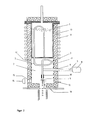
- FIGS. 1 and 2 Exemplary embodiments of the device according to the invention are shown schematically in FIGS. 1 and 2.
- the device is characterized in that the vibrating nozzle head (4), the feed line (2) for the liquid phase from the storage container (1) to the nozzle head (4) and a section of the drop drop section (6) until the formation of the exact spherical shape in one sealed, isothermal container (7) are arranged, the temperature of which can be kept constant in the range from 50 to 1500 ° C., preferably to 0.3 to 0.5%.
- the isothermal space can be flushed with an inert gas which is supplied and discharged via pipes (12).
- the vibration generator (8) is arranged outside the isothermal container (7) and mechanically coupled to the nozzle head (4) using a heat-insulating bushing (9) in such a way that the transmission of vibrations in the temperature range up to 1,500 C is ensured.
- the liquid is metered from the storage container (1) to the nozzle head (4) through a feed line (2) which has a spiral section (3).
- the oscillating total mass in the isothermal container (7) is kept constant in the range 0.1 to 1 kg by additional compensating masses (10).
- the container (7) has walls (13) made of a thermally insulating material and only has a larger opening in the area of the drop drop section (6).
- the liquid phase is conveyed through the feed line (2) in the isothermal container (7) and fed to the nozzle at the nozzle head (4).
- the vibration generator (8) which is located outside the isothermal container (7), causes the nozzle head (4) to oscillate periodically with the aid of a rigid connection (5), as a result of which the liquid jet flowing out of the nozzle disintegrates into uniform drops.
- the rigid connection (5) is in a heat-insulating bushing (9) and transmits the vibrations of the vibration generator (8) to the hot nozzle. In Figure 1, this is shown in a vertical version, in Figure 2 in a horizontal version.
- the substance to be dripped is melted in the storage container (1) or is already present as a melt.
- the temperature of the liquid in this container may be slightly more than 10 ° C above the melting temperature, and the temperature fluctuation may also be slightly greater than 0.5%.
- the feed line (2) which leads from the storage container (1) to the nozzle, is initially arranged outside the isothermal container (7) in the embodiment according to FIG. 1 and must therefore be heated and thermally insulated.
- the heater (11) can consist of electrical resistance wires.
- the liquid phase enters the feed line (2) inside the isothermal container (7), it takes on the temperature set there from 1 to 10 ° C. above its melting point.
- the dwell time required for this can preferably be adapted to the throughput in an ascending branch and an extension of the feed line (2) in the isothermal container (7).
- the materials used must be adapted to the respective requirements that are to be processed processing substances are determined. This can cause the weight of the vibrating mass to change from case to case.
- the use of differently sized nozzle heads (4) with more or fewer nozzles also changes the weight.
- compensating masses are preferably attached in front of or on the nozzle head (4), which ensure that the total oscillated total mass is almost constant in all cases.
- the process of droplet formation from a jet of liquid flowing from a nozzle depends, among other things. on the surface tension, density and viscosity of the liquid phase. Therefore, the drop distance (6) from the nozzle to the formation of the spherical shape must be determined empirically for each liquid.
- a stroboscopic lamp (14) is used, the light flashes of which make the process observable through the viewing window (15).
- a slight phase shift in the frequency of the stroboscopic lamp compared to that of the vibration generator even enables the oscillation processes of the drops to be observed after different falling distances, so that the point at which the drops have assumed a spherical shape can be precisely located.
- the falling drops are quenched with the cooling medium by blowing on the drops from the coolant supply (16), which is distributed uniformly around the nozzle head (4).
- the distance between the coolant supply (16) and the drops is a few centimeters. This ensures that the required temperature gradient of at least 100 ° C is maintained in a controlled manner.
- a nozzle plate with several nozzles of the same size and the same bore can be used on the nozzle head (4).
- the resulting increased mass is compensated for by a corresponding reduction in the balancing mass.
- the optimal number of nozzles on a nozzle plate is determined by the desired throughput, the geometrical possible conditions and the required cooling.
- the adaptation to the vibration system is not a problem.
- high-purity silver nitrate of melting point 209 C was melted in the storage container (1) and the temperature was raised to 225 C.
- the supply line (2) leading from there to the isothermal container (7) of a heating cabinet was heated to 220 ° C.
- the accuracy of the temperature control was better than + 1 C, correspondingly less than 0.5%.
- the diameter of the nozzle opening on the nozzle head (4) was 350 ⁇ m.
- the vibration that was transmitted from the vibration generator (8) to the nozzle head (4) had a frequency of 800 Hz.
- the flow rate of silver nitrate melt was 28.5 g / min., corresponding to 7.2 ml / min, taking into account the density of 3.96 g / cm 3 at the melting point. This corresponds to a throughput of 1.71 kg of silver nitrate per hour and nozzle, corresponding to the formation of 48,000 drops per minute and nozzle.
- the drop distance (6) was set to 5 cm after this drop distance had been assessed as optimal using the stroboscope (14).
- the drops were blown on both sides with compressed air from two nozzles of the coolant supply (16) with a diameter of 10 mm.
- the air metering for both nozzles was 500 l / h, the distance between the nozzles and the drops was set to 2 cm.
- the compressed air was at room temperature, so that the hot silver nitrate drops solidified very quickly at the temperature difference of 200 ° C. A slight suction in the direction of the drops resulted in a direct flow of drops and cooling gas and prevented cold air from entering the isothermal container (7).
- a total of 940 g of silver nitrate microspheres were produced.
- the yield of the sieve fraction 630-800 ⁇ m was 98.5%.
- the diameter distribution was measured on a representative sample, giving an average diameter of 653 ⁇ m with a percentage standard deviation of 3.6%.
- the balls were glassy, colorless to white and were characterized by very good roundness.
- the same experiment was carried out using a 10-fold nozzle head (4) with ten identical nozzles with a diameter of 350 ⁇ m.
- the temperature in the storage container (1) was 223 C and in the isothermal container (7) 216 ° C with a fluctuation range of less than 0.5%.
- the flow was 334 g / min, corresponding to 84.4 ml / min. This corresponds to a throughput of 20 kg of silver nitrate per hour.
- a soft solder alloy consisting of 63 percent by weight tin and 37 percent by weight lead, with a melting point of 183 ° C. was melted in the storage container (1), as shown in FIG. 1, and heated to 190 ° C., with temperature fluctuations of ⁇ 3 ° C. With a gas pressure of 0.79 bar, the melt was fed through the feed line (2) to the nozzle in the isothermal container (7).
- the temperature of the isothermal container (7) was adjusted to 187 ° C, the fluctuation range was less than 1 C.
- the nozzle opening had a diameter of 120 ⁇ m.
- the nozzle was excited by the vibration generator (8) to periodically vibrate at a frequency of 1,900 hertz.
- the isothermal container (7) was flushed with nitrogen gas of the "purest" quality until it was free of air.
- the gas above the melt in the storage container (1) and the cooling medium also consisted of pure nitrogen.
- the liquid alloy throughput was 7.2 g / min, from which 114,000 drops / min were formed. These drops were blown on both sides with pure nitrogen gas of 20 C from the nozzles of the coolant supply (16). The gas was discharged downwards in a cocurrent with the microspheres by gentle suction. After a drop distance of 3.5 m, which was additionally cooled to -10 ° C., the microspheres were collected in a container and then sieved.
- the yield of the 180-250 ⁇ m sieve fraction was 91.5%.
- a representative sample of 1,003 microspheres from this batch of sieves was measured.
- the mean diameter was 232 ⁇ m and the percentage standard deviation was 2.5%.
- the average weight of the microspheres was 63.4 ⁇ g, corresponding to a density of 9.60 g / cm 3 .
- the spheres showed a good roundness: more than 96% of all particles had a diameter ratio of large axis to small axis better than 1.03. Oxygen analysis of the microspheres showed values of less than 100 ppm.
- the frequency of the vibration excitation by the vibration generator (8) was 9,550 Hertz, with 573,000 drops being formed per minute.
- the throughput was 2.10 g / min per nozzle. This corresponds to a quantity of 756 g / h for the 6-fold nozzle plate.
- microspheres were sieved, yields of 93.8 and 88.3% of the sieve fraction 50-125 ⁇ m being achieved. Representative samples of these microspheres were measured to give mean diameters of 92 ⁇ m and 90 ⁇ m and percentage standard deviations of 7.6% and 9.8%, respectively.
- a device according to FIG. 2 was used to produce microspheres from silver solder.
- the silver solder used had a degree of purity of 99.9%, was oxide-free and had a melting point of 960 C.
- a stainless steel crucible was used as the storage container (1) for the silver melt, which was surrounded by insulation and was heated with the aid of an induction coil.
- a resistance-heated furnace room with heating (11) and insulation Below the steel crucible was a resistance-heated furnace room with heating (11) and insulation.
- the metering of the silver melt to the nozzle was carried out in a feed line (2), also made of stainless steel, which led through the bottom of the crucible into the isothermal container (7) and was shaped there into a spiral, whereby a certain elasticity was achieved.
- the rigid connection (5) between the vibration generator (8) and the nozzle head (4) was fastened below the spiral.
- the nozzle was also made of stainless steel and was firmly connected to the feed line (2).
- the silver melt was heated to 974 C, a temperature fluctuation of ⁇ 6 C occurring.
- the melt was metered through the feed line (2) in the isothermal container (7) to the nozzle head (4).
- the temperature in the isothermal container (7) was adjusted to 966 C with a fluctuation range of ⁇ 3 ⁇ C, corresponding to ⁇ 0.3%.
- the isothermal container (7) was rinsed air-free with pure starch.
- a periodic vibration of the frequency 200 Hz was transmitted from the vibration generator (8) to the nozzle head (4) via the rigid connection (5).
- the jet of liquid flowing out of the nozzle disintegrated into 12,000 drops per minute.
- the silver drops were blown laterally out of the nozzles (16) with argon gas from room temperature and thus suddenly solidified at the temperature difference of several hundred degrees.
- the microspheres were completely cooled and collected in a cooled steel sheet baffle in a steel container after collection.
- Example 3 Similar to Example 3, a device according to FIG. 2 was used for the production of spherical glass beads.
- the storage container (1), the feed line (2) and the nozzle head (4) with the pouring nozzles were made of platinum.
- the glass beads were made from soda-lime glass with the composition 65% by weight SiO 2 , 15% by weight Na 2 0 and 20% by weight CaO + MgO.
- the temperature of the glass melt in the storage container (1) was 1,450 ° C., in the isothermal container (7) 1,420 ° C. were set with an accuracy of ⁇ 5 ° C.
- the liquid glass was metered in at an air pressure of 1.30 bar through the feed line (2) to the single nozzle with a diameter of 520 ⁇ m. Under the influence of the vibrations of the vibration generator (8) of 500 Hz, uniform glass drops formed in the drop section (6), which were quenched 60 mm below the nozzle in the compressed air stream. The hot glass beads fell into a cooling pipe and were collected on the floor in a tub of water.
- the average diameter of the glass beads was determined to be 995 ⁇ m from a representative sample with a percentage standard deviation of 5.2%.
- the throughput was 2.25 kg glass per hour in the form of 1.8 million glass beads.
Landscapes
- Chemical & Material Sciences (AREA)
- Engineering & Computer Science (AREA)
- Organic Chemistry (AREA)
- Manufacturing & Machinery (AREA)
- Materials Engineering (AREA)
- Nanotechnology (AREA)
- Mechanical Engineering (AREA)
- Chemical Kinetics & Catalysis (AREA)
- Manufacture Of Metal Powder And Suspensions Thereof (AREA)
- Glanulating (AREA)
- Physical Or Chemical Processes And Apparatus (AREA)
- Processing And Handling Of Plastics And Other Materials For Molding In General (AREA)
Applications Claiming Priority (2)
| Application Number | Priority Date | Filing Date | Title |
|---|---|---|---|
| DE4022648 | 1990-07-17 | ||
| DE4022648A DE4022648C2 (de) | 1990-07-17 | 1990-07-17 | Verfahren und Vorrichtung zur Herstellung von kugelförmigen Teilchen aus flüssiger Phase |
Publications (3)
| Publication Number | Publication Date |
|---|---|
| EP0467221A2 true EP0467221A2 (fr) | 1992-01-22 |
| EP0467221A3 EP0467221A3 (en) | 1992-09-30 |
| EP0467221B1 EP0467221B1 (fr) | 1995-10-04 |
Family
ID=6410409
Family Applications (1)
| Application Number | Title | Priority Date | Filing Date |
|---|---|---|---|
| EP91111545A Expired - Lifetime EP0467221B1 (fr) | 1990-07-17 | 1991-07-11 | Procédé et installation pour la préparation de particules sphériques à partir d'une phase liquide |
Country Status (9)
| Country | Link |
|---|---|
| US (1) | US5183493A (fr) |
| EP (1) | EP0467221B1 (fr) |
| JP (1) | JPH0712422B2 (fr) |
| AT (1) | ATE128640T1 (fr) |
| CA (1) | CA2047151A1 (fr) |
| DE (2) | DE4022648C2 (fr) |
| DK (1) | DK0467221T3 (fr) |
| ES (1) | ES2077729T3 (fr) |
| GR (1) | GR3017886T3 (fr) |
Cited By (10)
| Publication number | Priority date | Publication date | Assignee | Title |
|---|---|---|---|---|
| WO1995013176A1 (fr) * | 1993-11-10 | 1995-05-18 | Nukem Gmbh | Procede et dispositif de production de particules en plastique |
| US5550170A (en) * | 1993-09-25 | 1996-08-27 | Huels Aktiengesellschaft | Process for the production of foam beads |
| WO1999003626A1 (fr) * | 1997-07-14 | 1999-01-28 | Aeroquip Corporation | Appareil et procede de production de spheres de taille et de forme uniformes |
| EP0905218A3 (fr) * | 1997-09-26 | 1999-11-03 | IRT-Innovative Recycling Technologie GmbH | Procédé de fabrication d'un granulat pour la création de germes d'allumage dans des combustibles et des combustibles propulseurs |
| WO2001000311A1 (fr) * | 1999-06-28 | 2001-01-04 | Boehringer Ingelheim Pharma Kg | Procede et dispositif pour la production de pastilles |
| DE10120612A1 (de) * | 2001-04-26 | 2002-11-21 | Omg Ag & Co Kg | Verfahren und Vorrichtung zur Herstellung von kugelförmigen Metallteilchen |
| DE102008036094A1 (de) | 2008-08-04 | 2010-02-11 | Brace Capital Gmbh | Sphärische Halbleitermetall Granulate |
| CN103008672A (zh) * | 2012-12-14 | 2013-04-03 | 大连理工大学 | 脉冲小孔多振动杆喷射法高效制备均一球形微粒子的方法及装置 |
| WO2016169795A1 (fr) * | 2015-04-21 | 2016-10-27 | Basf Se | Procédé de production de particules comprenant une cire hydrocarbonée en phase continue et un pesticide dispersé dans la phase continue en produisant des gouttelettes avec une buse vibrante |
| WO2017017153A1 (fr) * | 2015-07-28 | 2017-02-02 | Umicore Ag & Co. Kg | Acide bis(oxalato)platinique "on the rocks" |
Families Citing this family (41)
| Publication number | Priority date | Publication date | Assignee | Title |
|---|---|---|---|---|
| DE4031952A1 (de) * | 1990-10-09 | 1992-04-16 | Degussa | Verfahren zur herstellung von staubfreiem silbernitrat |
| US5294242A (en) * | 1991-09-30 | 1994-03-15 | Air Products And Chemicals | Method for making metal powders |
| DE4201589C1 (fr) * | 1992-01-22 | 1993-07-22 | Degussa Ag, 6000 Frankfurt, De | |
| DE4242645C2 (de) * | 1992-12-17 | 1997-12-18 | Deutsche Forsch Luft Raumfahrt | Verfahren und Einrichtung zur Herstellung von Metallkügelchen annähernd gleichen Durchmessers |
| US5609919A (en) * | 1994-04-21 | 1997-03-11 | Altamat Inc. | Method for producing droplets |
| US5683720A (en) * | 1994-10-28 | 1997-11-04 | Fuisz Technologies Ltd. | Liquiflash particles and method of making same |
| US6083430A (en) * | 1994-10-28 | 2000-07-04 | Fuisz Technologies Ltd. | Method of preparing a dosage unit by direct tableting and product therefrom |
| US6319507B1 (en) * | 1997-05-02 | 2001-11-20 | Kobo Products, Inc. | Agar gel bead composition and method |
| DE19801832C2 (de) * | 1998-01-14 | 2000-01-20 | Juergen Schulze | Verfahren und Vorrichtung zur Herstellung von kugelförmigen Teilchen nahezu gleichen Durchmessers |
| DE19845126A1 (de) * | 1998-09-30 | 2000-04-06 | Marco Systemanalyse Entw | Verfahren zur Tropfenbildung |
| EE200100660A (et) * | 1999-06-07 | 2003-04-15 | Byk Gulden Lomberg Chemische Fabrik Gmbh | Ravimvorm happe suhtes labiilsete toimeainete jaoks, toimeaine üksus, selle valmistamismeetod ja mikrokerake |
| US6284279B1 (en) * | 1999-12-03 | 2001-09-04 | Avecia, Inc. | Phenothiazine in prill form and method for making the same |
| DE10032137B4 (de) * | 2000-07-01 | 2009-04-02 | Allessachemie Gmbh | Verfahren zur Herstellung von Phenothiazin-Granulat mit verbesserten Eigenschaften |
| AU2001288660A1 (en) * | 2000-09-01 | 2002-03-13 | Fry's Metals, Inc. D/B/A Alpha Metals, Inc. | Rapid surface cooling of solder droplets by flash evaporation |
| US6579479B1 (en) | 2000-11-09 | 2003-06-17 | Honeywell International Inc. | Methods of forming a plurality of spheres; and pluralities of spheres |
| US6706959B2 (en) | 2000-11-24 | 2004-03-16 | Clean Venture 21 Corporation | Photovoltaic apparatus and mass-producing apparatus for mass-producing spherical semiconductor particles |
| WO2003000741A1 (fr) | 2001-06-22 | 2003-01-03 | Sekisui Chemical Co., Ltd. | Procede de preparation de particules de resine, particules de resine et appareil permettant de preparer lesdites particules |
| DE10160597A1 (de) * | 2001-12-10 | 2003-06-26 | Hte Ag The High Throughput Exp | Herstellung und Formgebung von Formkörpern mit Hilfe von Tiefkühl- und Trocknungs-Verfahren |
| BRPI0417492A (pt) * | 2003-12-09 | 2007-05-29 | Pfizer | composições compreendendo um inibidor de protease de hiv |
| WO2005096785A2 (fr) * | 2004-04-09 | 2005-10-20 | Synergy Innovations, Inc. | Systeme et procede de fabrication de particules spheriques dispersees d'une seule taille |
| EP1739212A1 (fr) * | 2004-04-21 | 2007-01-03 | Kyosemi Corporation | Appareil de fabrication de cristaux granulaires de type a compte-gouttes capillaire et procede de fabrication de cristaux granulaires |
| DE102004026725A1 (de) * | 2004-05-28 | 2005-12-15 | Cavis Microcaps Gmbh | Modulares Düsensystem zur Erzeugung von Tropfen aus Flüssigkeiten unterschiedlicher Viskosität |
| US7867613B2 (en) * | 2005-02-04 | 2011-01-11 | Oxane Materials, Inc. | Composition and method for making a proppant |
| US7491444B2 (en) * | 2005-02-04 | 2009-02-17 | Oxane Materials, Inc. | Composition and method for making a proppant |
| US8012533B2 (en) * | 2005-02-04 | 2011-09-06 | Oxane Materials, Inc. | Composition and method for making a proppant |
| ATE531895T1 (de) * | 2005-02-04 | 2011-11-15 | Oxane Materials Inc | Zusammensetzung und verfahren zur herstellung eines stützmittels |
| US8047288B2 (en) | 2007-07-18 | 2011-11-01 | Oxane Materials, Inc. | Proppants with carbide and/or nitride phases |
| KR101822208B1 (ko) * | 2009-11-02 | 2018-01-25 | 맨카인드 코포레이션 | 약학적 조성물을 극저온 과립화하는 장치 및 방법 |
| MX2012007248A (es) * | 2009-12-22 | 2012-07-30 | Oxane Materials Inc | Un consolidante que tiene un material de vidrio-ceramica. |
| EP2519473A4 (fr) | 2009-12-31 | 2016-12-07 | Halliburton Energy Services Inc | Particules de céramique ayant disposition et/ou taille de pores et/ou de microsphères réglées et procédé pour leur fabrication |
| WO2011094106A1 (fr) | 2010-01-29 | 2011-08-04 | Oxane Materials, Inc. | Agent de soutènement auto-durci à haute résistance et procédés de fabrication associés |
| JP5768956B2 (ja) * | 2010-12-24 | 2015-08-26 | 芝浦メカトロニクス株式会社 | 固体粒子の製造装置及び固体粒子の製造方法 |
| CA2828642A1 (fr) | 2011-03-02 | 2012-09-07 | Basf Se | Microcapsules d'acide alcansulfonique et leur utilisation lors de forages profonds |
| US8863841B2 (en) | 2011-03-02 | 2014-10-21 | Basf Se | Alkanesulfonic acid microcapsules and use thereof in deep wells |
| US9315719B2 (en) | 2011-07-13 | 2016-04-19 | Halliburton Energy Services, Inc. | Low surface friction proppants |
| EP3099639B1 (fr) * | 2014-01-27 | 2017-12-20 | Ingenieurbüro Franke GlasTechnologie-Service | Procédé et dispositif pour la fabrication de billes de verre creuses |
| JP6296036B2 (ja) * | 2015-10-13 | 2018-03-20 | トヨタ自動車株式会社 | 溶湯温度管理方法 |
| DE102015224974A1 (de) * | 2015-12-11 | 2017-06-14 | Forschungsinstitut Für Anorganische Werkstoffe - Glas Keramik Gmbh | Verfahren und Vorrichtung zum Herstellen von einen sinterfähigen Stoff enthaltenden Mikrokugeln |
| EP3797861A1 (fr) * | 2019-09-24 | 2021-03-31 | Casale Sa | Procédé et syteme de commande d'un godet de grelonage vibrant dans un procédé de grelonage d'urée |
| CN117123788B (zh) * | 2023-08-29 | 2026-02-13 | 中国机械总院集团宁波智能机床研究院有限公司 | 一种铜核球及其制备方法、装置 |
| CN117428198A (zh) * | 2023-10-30 | 2024-01-23 | 云南前沿液态金属研究院有限公司 | 一种bga金属球形颗粒的制备方法 |
Family Cites Families (18)
| Publication number | Priority date | Publication date | Assignee | Title |
|---|---|---|---|---|
| US2968833A (en) * | 1957-05-17 | 1961-01-24 | Phillips Petroleum Co | Method and apparatus for prilling ammonium nitrate |
| JPS5030781A (fr) * | 1973-07-21 | 1975-03-27 | ||
| US4419303A (en) * | 1976-02-02 | 1983-12-06 | Scott Anderson | Method for producing large diameter high purity sodium amalgam particles |
| DE2725924C3 (de) * | 1977-06-08 | 1980-11-06 | Hobeg Hochtemperaturreaktor-Brennelement Gmbh, 6450 Hanau | Verfahren zur Herstellung kugelförmiger Teilchen aus niedrigschmelzenden organischen Substanzen |
| JPS5623882A (en) * | 1979-08-07 | 1981-03-06 | Snow Brand Milk Prod Co Ltd | Preparation of frozen material of granular shape |
| FR2471827A1 (fr) * | 1979-12-21 | 1981-06-26 | Extramet Sa | Dispositif pour la production de granules metalliques uniformes |
| CA1154213A (fr) * | 1981-07-07 | 1983-09-27 | Cominco Ltd. | Granulation du soufre |
| JPS5910333A (ja) * | 1982-07-12 | 1984-01-19 | Nippon Kagaku Sangyo Kk | 有機酸金属塩の造粒方法 |
| JPS5925904A (ja) * | 1982-08-04 | 1984-02-10 | Toyo Alum Kk | 金属粉製造装置および金属粉製造方法 |
| JPS59136127A (ja) * | 1983-01-21 | 1984-08-04 | Kanegafuchi Chem Ind Co Ltd | 液滴生成法およびそれに用いる装置 |
| DE3319508A1 (de) * | 1983-05-03 | 1984-11-08 | BBC Aktiengesellschaft Brown, Boveri & Cie., Baden, Aargau | Vorrichtung und verfahren zur zerstaeubung von fluessigen metallen zwecks erzeugung eines feinkoernigen pulvers |
| FR2571980A1 (fr) * | 1984-10-22 | 1986-04-25 | Extramet Sa | Procede et dispositif de fabrication de micro-billes calibrees et micro-billes obtenues. |
| JPS61221310A (ja) * | 1985-03-26 | 1986-10-01 | Agency Of Ind Science & Technol | 金属或は合金等の微粉末製造方法とその装置 |
| US4774037A (en) * | 1986-09-26 | 1988-09-27 | The United States Of America As Represented By The United States Department Of Energy | Method for producing solid or hollow spherical particles of chosen chemical composition and of uniform size |
| JPH0628720B2 (ja) * | 1986-11-12 | 1994-04-20 | 鐘淵化学工業株式会社 | 均一液滴の製造装置 |
| DE3735787A1 (de) * | 1987-09-22 | 1989-03-30 | Stiftung Inst Fuer Werkstoffte | Verfahren und vorrichtung zum zerstaeuben mindestens eines strahls eines fluessigen stoffs, vorzugsweise geschmolzenen metalls |
| JPH0829014B2 (ja) * | 1987-10-02 | 1996-03-27 | 井関農機株式会社 | 歩行型田植機 |
| JPH02227130A (ja) * | 1989-02-28 | 1990-09-10 | Taisho Pharmaceut Co Ltd | 球形微小凍結粒子の製造法 |
-
1990
- 1990-07-17 DE DE4022648A patent/DE4022648C2/de not_active Expired - Fee Related
-
1991
- 1991-07-08 US US07/726,803 patent/US5183493A/en not_active Expired - Lifetime
- 1991-07-11 DK DK91111545.9T patent/DK0467221T3/da active
- 1991-07-11 AT AT91111545T patent/ATE128640T1/de not_active IP Right Cessation
- 1991-07-11 ES ES91111545T patent/ES2077729T3/es not_active Expired - Lifetime
- 1991-07-11 DE DE59106612T patent/DE59106612D1/de not_active Expired - Lifetime
- 1991-07-11 EP EP91111545A patent/EP0467221B1/fr not_active Expired - Lifetime
- 1991-07-16 CA CA002047151A patent/CA2047151A1/fr not_active Abandoned
- 1991-07-17 JP JP3177020A patent/JPH0712422B2/ja not_active Expired - Lifetime
-
1995
- 1995-10-25 GR GR950402994T patent/GR3017886T3/el unknown
Cited By (16)
| Publication number | Priority date | Publication date | Assignee | Title |
|---|---|---|---|---|
| US5550170A (en) * | 1993-09-25 | 1996-08-27 | Huels Aktiengesellschaft | Process for the production of foam beads |
| WO1995013176A1 (fr) * | 1993-11-10 | 1995-05-18 | Nukem Gmbh | Procede et dispositif de production de particules en plastique |
| EP1275434A3 (fr) * | 1997-07-14 | 2004-08-04 | Alpha Metals (Korea) Ltd. | Appareil et procédé de production de spheres de tailles et de formes uniformes |
| WO1999003626A1 (fr) * | 1997-07-14 | 1999-01-28 | Aeroquip Corporation | Appareil et procede de production de spheres de taille et de forme uniformes |
| US5891212A (en) * | 1997-07-14 | 1999-04-06 | Aeroquip Corporation | Apparatus and method for making uniformly |
| US6083454A (en) * | 1997-07-14 | 2000-07-04 | Aeroquip Corporation | Apparatus and method for making uniformly sized and shaped spheres |
| USRE39224E1 (en) * | 1997-07-14 | 2006-08-08 | Alpha Metals (Korea) Ltd. | Apparatus and method for making uniformly sized and shaped spheres |
| EP0905218A3 (fr) * | 1997-09-26 | 1999-11-03 | IRT-Innovative Recycling Technologie GmbH | Procédé de fabrication d'un granulat pour la création de germes d'allumage dans des combustibles et des combustibles propulseurs |
| WO2001000311A1 (fr) * | 1999-06-28 | 2001-01-04 | Boehringer Ingelheim Pharma Kg | Procede et dispositif pour la production de pastilles |
| DE10120612A1 (de) * | 2001-04-26 | 2002-11-21 | Omg Ag & Co Kg | Verfahren und Vorrichtung zur Herstellung von kugelförmigen Metallteilchen |
| DE102008036094A1 (de) | 2008-08-04 | 2010-02-11 | Brace Capital Gmbh | Sphärische Halbleitermetall Granulate |
| CN103008672A (zh) * | 2012-12-14 | 2013-04-03 | 大连理工大学 | 脉冲小孔多振动杆喷射法高效制备均一球形微粒子的方法及装置 |
| CN103008672B (zh) * | 2012-12-14 | 2015-08-19 | 大连理工大学 | 脉冲小孔多振动杆喷射法高效制备均一球形微粒子的方法及装置 |
| WO2016169795A1 (fr) * | 2015-04-21 | 2016-10-27 | Basf Se | Procédé de production de particules comprenant une cire hydrocarbonée en phase continue et un pesticide dispersé dans la phase continue en produisant des gouttelettes avec une buse vibrante |
| WO2017017153A1 (fr) * | 2015-07-28 | 2017-02-02 | Umicore Ag & Co. Kg | Acide bis(oxalato)platinique "on the rocks" |
| CN107922304A (zh) * | 2015-07-28 | 2018-04-17 | 优美科股份公司及两合公司 | “带冰”的双(草酸)合铂酸 |
Also Published As
| Publication number | Publication date |
|---|---|
| DE4022648C2 (de) | 1994-01-27 |
| US5183493A (en) | 1993-02-02 |
| GR3017886T3 (en) | 1996-01-31 |
| ATE128640T1 (de) | 1995-10-15 |
| DK0467221T3 (da) | 1996-02-19 |
| EP0467221B1 (fr) | 1995-10-04 |
| ES2077729T3 (es) | 1995-12-01 |
| DE4022648A1 (de) | 1992-01-23 |
| EP0467221A3 (en) | 1992-09-30 |
| JPH0712422B2 (ja) | 1995-02-15 |
| JPH04227043A (ja) | 1992-08-17 |
| DE59106612D1 (de) | 1995-11-09 |
| CA2047151A1 (fr) | 1992-01-18 |
Similar Documents
| Publication | Publication Date | Title |
|---|---|---|
| EP0467221B1 (fr) | Procédé et installation pour la préparation de particules sphériques à partir d'une phase liquide | |
| DE69814860T2 (de) | Verfahren und vorrichtung zur herstellung von kugeln mit uniformer grösse und form | |
| DE68917132T2 (de) | Verfahren und vorrichtung zum zerstäuben einer metallschmelze. | |
| DE69423959T2 (de) | Herstellung von pulver | |
| AT502777B1 (de) | Verfahren zur herstellung von partikeln aus einem keramischen werkstoff | |
| DE3505660A1 (de) | Vorrichtung und verfahren zum zerstaeuben instabiler schmelzstroeme | |
| DE2725924C3 (de) | Verfahren zur Herstellung kugelförmiger Teilchen aus niedrigschmelzenden organischen Substanzen | |
| EP0361396B1 (fr) | Procédé et installation de préparation d'une poudre amorphe d'une matière céramique ou métallique | |
| DE3730147A1 (de) | Verfahren zur herstellung von pulvern aus geschmolzenen stoffen | |
| EP0007352A1 (fr) | Granulats obtenus à partir de masses en fusion, procédé et dispositif de fabrication. | |
| EP1042093B1 (fr) | Procede et dispositif pour produire des poudres fines par atomisation de matieres fondues avec des gaz | |
| DE1583715C3 (de) | Verfahren zum Kühlen eines schmelzflüssigen Drahtes oder Fadens | |
| DE2725849B2 (de) | Vorrichtung zur Herstellung von kugelförmigen Teilchen | |
| DE1496434B2 (de) | Verfahren und Vorrichtung zur Herstellung von Glasperlen | |
| DE2634617A1 (de) | Verfahren zur herstellung von magnetitkugeln und einrichtung zur durchfuehrung des verfahrens | |
| DE69519334T2 (de) | Perlförmiges Vanillin oder Ethylvanillin und Verfahren zu deren Herstellung | |
| DE3126854C2 (de) | Verfahren und Vorrichtung zur Herstellung kugelförmiger Teilchen aus spontan reagierenden flüssigen Komponenten | |
| DE2635373A1 (de) | Verfahren und vorrichtung zur kontinuierlichen zuechtung von einkristallen bestimmter form | |
| DE3124200C2 (de) | Verfahren zur Herstellung von Schwefel in Granulatform | |
| DE60128119T2 (de) | Verfahren zur herstellung von pulver aus kernbrennstoffmetall oder -metalllegierung | |
| DE2518848A1 (de) | Prillierverfahren und vorrichtung zu dessen durchfuehrung | |
| EP1222147B1 (fr) | Procede et dispositif permettant de produire des poudres composees de particules sensiblement spheriques | |
| DE3150221A1 (de) | Verfahren und vorrichtung zur herstellung von metallpulver aus einer schmelze | |
| DE69520384T2 (de) | Kleine Kugeln von Kumarin und/oder Derivate und Verfahren zu deren Herstellung | |
| EP1108465A2 (fr) | Produits formés et coulant d'amide de nicotine et leur procédé de préparation |
Legal Events
| Date | Code | Title | Description |
|---|---|---|---|
| PUAI | Public reference made under article 153(3) epc to a published international application that has entered the european phase |
Free format text: ORIGINAL CODE: 0009012 |
|
| AK | Designated contracting states |
Kind code of ref document: A2 Designated state(s): AT BE CH DE DK ES FR GB GR IT LI LU NL SE |
|
| PUAL | Search report despatched |
Free format text: ORIGINAL CODE: 0009013 |
|
| AK | Designated contracting states |
Kind code of ref document: A3 Designated state(s): AT BE CH DE DK ES FR GB GR IT LI LU NL SE |
|
| 17P | Request for examination filed |
Effective date: 19921111 |
|
| 17Q | First examination report despatched |
Effective date: 19931207 |
|
| GRAA | (expected) grant |
Free format text: ORIGINAL CODE: 0009210 |
|
| AK | Designated contracting states |
Kind code of ref document: B1 Designated state(s): AT BE CH DE DK ES FR GB GR IT LI LU NL SE |
|
| REF | Corresponds to: |
Ref document number: 128640 Country of ref document: AT Date of ref document: 19951015 Kind code of ref document: T |
|
| REF | Corresponds to: |
Ref document number: 59106612 Country of ref document: DE Date of ref document: 19951109 |
|
| REG | Reference to a national code |
Ref country code: ES Ref legal event code: FG2A Ref document number: 2077729 Country of ref document: ES Kind code of ref document: T3 |
|
| ITF | It: translation for a ep patent filed | ||
| ET | Fr: translation filed | ||
| REG | Reference to a national code |
Ref country code: GR Ref legal event code: FG4A Free format text: 3017886 |
|
| GBT | Gb: translation of ep patent filed (gb section 77(6)(a)/1977) |
Effective date: 19951123 |
|
| REG | Reference to a national code |
Ref country code: DK Ref legal event code: T3 |
|
| PGFP | Annual fee paid to national office [announced via postgrant information from national office to epo] |
Ref country code: GR Payment date: 19960617 Year of fee payment: 6 |
|
| PGFP | Annual fee paid to national office [announced via postgrant information from national office to epo] |
Ref country code: SE Payment date: 19960618 Year of fee payment: 6 |
|
| PGFP | Annual fee paid to national office [announced via postgrant information from national office to epo] |
Ref country code: DK Payment date: 19960627 Year of fee payment: 6 |
|
| PGFP | Annual fee paid to national office [announced via postgrant information from national office to epo] |
Ref country code: BE Payment date: 19960711 Year of fee payment: 6 |
|
| PGFP | Annual fee paid to national office [announced via postgrant information from national office to epo] |
Ref country code: NL Payment date: 19960731 Year of fee payment: 6 |
|
| PLBE | No opposition filed within time limit |
Free format text: ORIGINAL CODE: 0009261 |
|
| STAA | Information on the status of an ep patent application or granted ep patent |
Free format text: STATUS: NO OPPOSITION FILED WITHIN TIME LIMIT |
|
| 26N | No opposition filed | ||
| PG25 | Lapsed in a contracting state [announced via postgrant information from national office to epo] |
Ref country code: DK Free format text: LAPSE BECAUSE OF NON-PAYMENT OF DUE FEES Effective date: 19970711 |
|
| REG | Reference to a national code |
Ref country code: DK Ref legal event code: EBP |
|
| PG25 | Lapsed in a contracting state [announced via postgrant information from national office to epo] |
Ref country code: SE Effective date: 19970712 |
|
| PGFP | Annual fee paid to national office [announced via postgrant information from national office to epo] |
Ref country code: AT Payment date: 19970724 Year of fee payment: 7 |
|
| PG25 | Lapsed in a contracting state [announced via postgrant information from national office to epo] |
Ref country code: BE Free format text: LAPSE BECAUSE OF NON-PAYMENT OF DUE FEES Effective date: 19970731 Ref country code: GR Free format text: LAPSE BECAUSE OF NON-PAYMENT OF DUE FEES Effective date: 19970731 |
|
| PGFP | Annual fee paid to national office [announced via postgrant information from national office to epo] |
Ref country code: ES Payment date: 19970925 Year of fee payment: 7 |
|
| PGFP | Annual fee paid to national office [announced via postgrant information from national office to epo] |
Ref country code: LU Payment date: 19970930 Year of fee payment: 7 |
|
| BERE | Be: lapsed |
Owner name: NUKEM G.M.B.H. Effective date: 19970731 |
|
| PG25 | Lapsed in a contracting state [announced via postgrant information from national office to epo] |
Ref country code: NL Free format text: LAPSE BECAUSE OF NON-PAYMENT OF DUE FEES Effective date: 19980201 |
|
| NLV4 | Nl: lapsed or anulled due to non-payment of the annual fee |
Effective date: 19980201 |
|
| EUG | Se: european patent has lapsed |
Ref document number: 91111545.9 |
|
| PG25 | Lapsed in a contracting state [announced via postgrant information from national office to epo] |
Ref country code: AT Free format text: LAPSE BECAUSE OF NON-PAYMENT OF DUE FEES Effective date: 19980711 Ref country code: LU Free format text: LAPSE BECAUSE OF NON-PAYMENT OF DUE FEES Effective date: 19980711 |
|
| PG25 | Lapsed in a contracting state [announced via postgrant information from national office to epo] |
Ref country code: ES Free format text: LAPSE BECAUSE OF THE APPLICANT RENOUNCES Effective date: 19980713 |
|
| REG | Reference to a national code |
Ref country code: GB Ref legal event code: 732E |
|
| REG | Reference to a national code |
Ref country code: FR Ref legal event code: TP |
|
| REG | Reference to a national code |
Ref country code: GB Ref legal event code: 746 Effective date: 19981111 |
|
| REG | Reference to a national code |
Ref country code: CH Ref legal event code: PUE Owner name: NUKEM GMBH TRANSFER- BRANDAU, EGBERT, DR. |
|
| REG | Reference to a national code |
Ref country code: FR Ref legal event code: ST |
|
| REG | Reference to a national code |
Ref country code: FR Ref legal event code: RN |
|
| REG | Reference to a national code |
Ref country code: FR Ref legal event code: FC |
|
| REG | Reference to a national code |
Ref country code: ES Ref legal event code: FD2A Effective date: 20001009 |
|
| PGFP | Annual fee paid to national office [announced via postgrant information from national office to epo] |
Ref country code: FR Payment date: 20010718 Year of fee payment: 11 |
|
| PGFP | Annual fee paid to national office [announced via postgrant information from national office to epo] |
Ref country code: GB Payment date: 20010719 Year of fee payment: 11 |
|
| PGFP | Annual fee paid to national office [announced via postgrant information from national office to epo] |
Ref country code: CH Payment date: 20010726 Year of fee payment: 11 |
|
| REG | Reference to a national code |
Ref country code: GB Ref legal event code: IF02 |
|
| PG25 | Lapsed in a contracting state [announced via postgrant information from national office to epo] |
Ref country code: GB Free format text: LAPSE BECAUSE OF NON-PAYMENT OF DUE FEES Effective date: 20020711 |
|
| PG25 | Lapsed in a contracting state [announced via postgrant information from national office to epo] |
Ref country code: CH Free format text: LAPSE BECAUSE OF NON-PAYMENT OF DUE FEES Effective date: 20020731 Ref country code: LI Free format text: LAPSE BECAUSE OF NON-PAYMENT OF DUE FEES Effective date: 20020731 |
|
| GBPC | Gb: european patent ceased through non-payment of renewal fee |
Effective date: 20020711 |
|
| REG | Reference to a national code |
Ref country code: CH Ref legal event code: PL |
|
| PG25 | Lapsed in a contracting state [announced via postgrant information from national office to epo] |
Ref country code: FR Free format text: LAPSE BECAUSE OF NON-PAYMENT OF DUE FEES Effective date: 20030331 |
|
| REG | Reference to a national code |
Ref country code: FR Ref legal event code: ST |
|
| PG25 | Lapsed in a contracting state [announced via postgrant information from national office to epo] |
Ref country code: IT Free format text: LAPSE BECAUSE OF NON-PAYMENT OF DUE FEES;WARNING: LAPSES OF ITALIAN PATENTS WITH EFFECTIVE DATE BEFORE 2007 MAY HAVE OCCURRED AT ANY TIME BEFORE 2007. THE CORRECT EFFECTIVE DATE MAY BE DIFFERENT FROM THE ONE RECORDED. Effective date: 20050711 |
|
| PGFP | Annual fee paid to national office [announced via postgrant information from national office to epo] |
Ref country code: DE Payment date: 20100802 Year of fee payment: 20 |
|
| REG | Reference to a national code |
Ref country code: DE Ref legal event code: R071 Ref document number: 59106612 Country of ref document: DE |
|
| REG | Reference to a national code |
Ref country code: DE Ref legal event code: R071 Ref document number: 59106612 Country of ref document: DE |
|
| PG25 | Lapsed in a contracting state [announced via postgrant information from national office to epo] |
Ref country code: DE Free format text: LAPSE BECAUSE OF EXPIRATION OF PROTECTION Effective date: 20110712 |