EP0467301A2 - Kassette für eine einzelne Reihe von Reagenzröhrchen oder dergleichen - Google Patents
Kassette für eine einzelne Reihe von Reagenzröhrchen oder dergleichen Download PDFInfo
- Publication number
- EP0467301A2 EP0467301A2 EP91111862A EP91111862A EP0467301A2 EP 0467301 A2 EP0467301 A2 EP 0467301A2 EP 91111862 A EP91111862 A EP 91111862A EP 91111862 A EP91111862 A EP 91111862A EP 0467301 A2 EP0467301 A2 EP 0467301A2
- Authority
- EP
- European Patent Office
- Prior art keywords
- receptacles
- containers
- upper edge
- area
- platform
- Prior art date
- Legal status (The legal status is an assumption and is not a legal conclusion. Google has not performed a legal analysis and makes no representation as to the accuracy of the status listed.)
- Granted
Links
Images


Classifications
-
- B—PERFORMING OPERATIONS; TRANSPORTING
- B01—PHYSICAL OR CHEMICAL PROCESSES OR APPARATUS IN GENERAL
- B01L—CHEMICAL OR PHYSICAL LABORATORY APPARATUS FOR GENERAL USE
- B01L9/00—Supporting devices; Holding devices
- B01L9/06—Test-tube stands; Test-tube holders
-
- B—PERFORMING OPERATIONS; TRANSPORTING
- B01—PHYSICAL OR CHEMICAL PROCESSES OR APPARATUS IN GENERAL
- B01L—CHEMICAL OR PHYSICAL LABORATORY APPARATUS FOR GENERAL USE
- B01L2200/00—Solutions for specific problems relating to chemical or physical laboratory apparatus
- B01L2200/02—Adapting objects or devices to another
- B01L2200/025—Align devices or objects to ensure defined positions relative to each other
-
- G—PHYSICS
- G01—MEASURING; TESTING
- G01N—INVESTIGATING OR ANALYSING MATERIALS BY DETERMINING THEIR CHEMICAL OR PHYSICAL PROPERTIES
- G01N35/00—Automatic analysis not limited to methods or materials provided for in any single one of groups G01N1/00 - G01N33/00; Handling materials therefor
- G01N35/02—Automatic analysis not limited to methods or materials provided for in any single one of groups G01N1/00 - G01N33/00; Handling materials therefor using a plurality of sample containers moved by a conveyor system past one or more treatment or analysis stations
- G01N35/026—Automatic analysis not limited to methods or materials provided for in any single one of groups G01N1/00 - G01N33/00; Handling materials therefor using a plurality of sample containers moved by a conveyor system past one or more treatment or analysis stations having blocks or racks of reaction cells or cuvettes
Definitions
- the invention relates to a device comprising a plurality of receptacles (2) which are arranged in a single row and in which containers (30, 35, 36) filled with a liquid and being of different height and diameter are fixed and centered and whose openings (31) are aligned at a predetermined level, the exterior walls (4) of said receptacles (2) being provided with apertures (3) for scanning the containers (30, 35, 36) during their transport through an analyzer.
- Devices for holding and transporting containers filled with a liquid which are used in an analyzer to process a number of body fluids or samples to be examined.
- EP-B-0 159 346 discloses a cassette for holding a plurality of liquid containers arranged in a single row and having different diameters and/or different lengths for transporting the containers to a testing station.
- the openings of the containers are located at the same level and the containers are centered and fixed by means of a spring element.
- the containers sealed by stoppers are transported horizontally and for liquid removal are moved to an inclined position in which the stopper points downwards. For removing the liquid, the stopper is pierced by the hollow needle of an aspirator.
- the above object is attained in that in a vertically extending arrangement different elements (5) are provided for supporting at least one loose platform (20) transversing the receptacles (2).
- the holding elements can be arranged along one of the sides of device at the exterior wall of the receptacles and define cavities or elevations.
- the holding means of the platform and the mounting means of the adapter are partly formed as positioning means and/or latch means.
- both the platform and the bottom surface of the base of the device within the receptacles are formed as a ramp.
- a recess is provided in the area of the upper edge of the exterior wall which together with the ramp serves for positioning purposes.
- a carrying means is provided comprising a handle, a cam and a support, with the cam being formed as an inclined surface arranged at the upper portion of the handle and the support being provided with a trough and a slope arranged at the lower portion of the handle.
- the advantageously designed carrying means in connection with a widened base of the tray, guarantees failsafe handling of the containers inside and outside the analyzer.
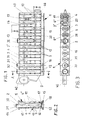
- a tray 1 shown in Figs. 1, 2 and 3 consists of a plurality of receptacles 2 arranged in a single row for holding containers 30, 35, of a base 15, a carrying means 40 at an end face 9 and an eyelet-shaped entrainment member 48 at the opposed end face 49.
- Receptacles 2 are enclosed by walls and have an octagonal crosssection.
- holding elements 5 are arranged for one or several platforms 20, apertures 3 and an uninterrupted protruding rim at the upper edge 14.
- the holding elements 5 shaped as cavities 7 are arranged at three different levels along a side 6 of tray 1. In the area of the end face 49 and in the central portion of tray 1 the holding elements 5 are vertically arranged and have wider slots so as to form positioning means 10 for the platform 20.
- Latch means 11 which in the area of the apertures 3 at the outer edges of the exterior walls 4 are designed as depressions, are associated with said positioning means 10 and are arranged on the opposite side 6'.
- the latch means thus, are used for holding and, in addition, for supporting a platform 20 transversing the receptacles 2.
- the apertures 3 and 3' formed in the exterior walls 4 and 4' of the receptacles 2 are designed as vertically extending slots starting in the area of base 15. At the side 6' of tray 1 they end below the upper edge 14 and at the opposite side 6 they extend through the upper edge 14. At the upper edge 14, each of the apertures 3 is provided with a recess 13 adapted to the different diameters of the various containers 30, 35, 36.
- the widened apertures 3 arranged beneath the recesses 13 are intended for scanning the containers 30, 35, 36 by an automatic scanning means. Furthermore, the apertures 3 and 3' provided with index marks arranged on the exterior walls 4 and 4' are used for visually detecting the liquid level within the containers.
- the base 15 of tray 1 has a lower section which measured across the longitudinally extending exterior walls 4 and 4' is wider than the receptacles 2.
- the wider section of base 15 serves to increase stability and to guide and retain device 1 on a transport path in an analyzer.
- each receptacle 2 In the upper section of base 15 serving as a support a ramp 12 is arranged in each receptacle 2.
- the higher edge 16 of ramp 12 faces recess 13 in the exterior wall 4 and along the central axis of its inclined surface 17 the ramp 12 has a slot-shaped opening 18 with the upper edge being chamfered.
- the opening and the chamfered edge are adapted to shape and size of the bottom of a container.
- ramp 12 When a container 30 or 35 is placed in receptacle 2, ramp 12 effects a lateral tilt of the container towards the recess 13 at the upper edge 14 of exterior wall 4 so that the upper portion of the container 30 or 35 is centered and clamped in recess 13 and its lower portion between ramp 12 and the exterior wall 4'. This facilitates insertion and removal of the containers 30 or 35 and fixes them in tray 1 in a defined and stable position for subsequent transport.
- the octagonal cross-section of receptacle 2 permits an additional centered position of container 30, 35 which is opposite to the first position and taken when a container is present in one of the processing stations.
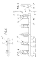
- Figs. 4, 5 and 6 show a platform 20 adapted to the structure of tray 1 according to Figs. 1, 2 and 3.
- Platform 20 consists of a connecting member 21 of rectangular cross-section which on one side is provided with a plurality of ramps 12' at a distance corresponding to that of the individual receptacles 2 of tray 1.
- the higher edge 16' of ramp 12' faces the connecting member 21.
- Ramp 12' is comprised of two ribs 22 arranged on a base plate 25 having a slot-shaped opening 18' with shape and dimensions corresponding to ramp 12 in base 15 of tray 1.
- the two exterior ramps 12' comprise latch means 11' having detents 23 and a slot 26 at the outer end of each base plate 25. Furthermore, the two base plates 25 are provided with outwardly directed lateral guide surfaces 27 extending beyond connecting member 21. On its upper side, one of said guide surfaces 27 has a positioning means 10' also extending beyond the adjacent protruding end portion of connecting member 21.
- Platform 20 is used when the openings 31 of containers 36 which are lower in height than the containers 30 and 35 are to be aligned to a predetermined level above the upper edge 14 of tray 1, which is required for processing (see Fig. 1).
- one or two platforms 20 are inserted in the holding elements 5 of tray 1 at the level required.
- Ramp 12' of platform 20 thereby penetrates the apertures 3, 3' and is positioned in the receptacle 2 normal to the longitudinal axis thereof, with the detents 23 engaging with the depressions of latch means 11 and the connecting member 21 abutting at the bottom of the holding elements 5.
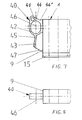
- the carrying means 40 of tray 1 shown in Fig. 7 is comprised of a cam 41, a handle 42 and a support 43. It is arranged in the upper area of end face 9 of tray 1 and in alignment with the longitudinal central axis of the device, with the center axis 46 of handle 42 formed as an oval ring extending horizontally and transversely with respect to the central axis of device 1.
- Cam 41 is arranged at the upper end portion of handle 42 and support 43 at the lower.
- Cam 41 has an inclined surface 44 whose lower end is connected with the upper edge 14 of tray 1 via a trough-shaped section 44'.
- the upper end of cam 41 is rounded off and changes over into the outer surface of handle 42.
- Support 43 is connected to handle 42 by means of a trough 45.
- a slope 47 extends between the lower end of trough 45 and the upper edge of base 15.
- a slope 47 is provided for easy manual removal of tray 1 from the analyzer with a retaining means in the tray track of an input station having to be overcome.
- Slope 47 is designed as a narrow web, whereas cam 41, handle 42 and support 43 are somewhat wider.
- the dimensions of the components such as cam 41, handle 42 and support 43, used when carrying tray 1 are adapted to the anatomy of the human hand to assure reliable and easy handling of tray 1.
- width, radii and shape of the components mentioned as well as the diameter of the handle are adapted to the dimensions of the thumb, the forefinger and the middle finger.
- Figs. 9, 10 and 11 show an adapter 60 for holding small containers 70 which is placed on tray 1 and fixed thereon, with the receptacles 62 of adapter 60 being associated with the receptacles 2 of tray 1 so as to be in alignment therewith, and the adapter completely covering the device.
- mounting means 50 are provided in the form of rectangular recesses 52 and projections 53 on the upper edge 14 of tray 1 at the outwardly projecting rim 54.
- Downwardly extending and projecting latch means 65 are provided on adapter 60 which are associated with the mounting means 50. At the lower end of their inner surfaces, the resiliently designed latch means 65 have latching nipples 66 engaging with the projections 53 of mounting means 50 from below.
- the mounting means 50 are arranged unsymmetrically at the rim 54 such that one of the mounting means 50 is provided in the center of the side 6' and two mounting means are provided outside the center on the side 6 of tray 1.
- guides 67 are arranged which project beyond the end faces 9 and 49 of tray 1, with the guides 67 arranged on the end face 9 extending on both sides of the carrying means 40.
- the guides 67 permit the adapter 60 to be placed on a support surface.
- Figs. 12, 13 and 14 show the adapter 60 as an individual part. Supplementing the features described in Figs. 9, 10 and 11, the adapter 60 shows that the receptacles 61 are designed as hollow cylinders, are vertically aligned in a row on a support plate 68.
- the receptacles 61 downwardly project beyond the support plate 68 of adapter 60 to the extent that their end portions are positioned in the area of the widening of the apertures 3 of tray 1 when the support plate 68 rests on tray 1.
- apertures 64 are provided in each of the receptacles 61 in the form of a vertically extending slot which starts above the lower edge of the receptacle and within the widening of the aperture of tray 1 and extends as far as the upper edge of receptacle 61.
- Two additional apertures 64' are provided in the form of vertical slots which start above support plate 68 and also extend as far as the upper edge of receptacle 61. With respect to apertures 64, apertures 64' are offset by an angle of 120° so as to form three tongues 69.
- each tongue 69 is provided with a supporting means 62 within the receptacle 61 which means is designed in the form of a shoulder provided within the upwardly widening opening of receptacle 61.
- the inner diameter is adapted to an upper rim of the cylindrical small container 70 which protrudes to a larger extent.
- the wall thickness of the end portions of the tongues 69 decreases inwardly above the supporting means 62, thus said end portions forming resilient centering/fixing means 63.
- the exterior shoulder of the centering/fixing means 63 is designed such that a lid 72 can be placed over it and the small containers 70 can be covered to protect the body fluids against fouling and evaporation.
- this design of the receptacles 61 permits the small containers 70 to be easily inserted and removed and securely to be transported by means of the adapter 60 or the tray 1 within and outside an analyzer.
- Aperture 64 in receptacle 61 additionally serves for scanning the small containers 70 and the lower end portion of receptacle 61 is used for scanning the adapter 60.
- Wall 71 protects the small containers 70 and their lids 72 against inadvertent contact when the adapter is manually handled, and also serves for stowing a tab arranged on the lid 72.
Landscapes
- Health & Medical Sciences (AREA)
- Clinical Laboratory Science (AREA)
- Chemical & Material Sciences (AREA)
- Chemical Kinetics & Catalysis (AREA)
- Automatic Analysis And Handling Materials Therefor (AREA)
- Sampling And Sample Adjustment (AREA)
Applications Claiming Priority (2)
| Application Number | Priority Date | Filing Date | Title |
|---|---|---|---|
| DE4023194 | 1990-07-20 | ||
| DE4023194A DE4023194A1 (de) | 1990-07-20 | 1990-07-20 | Vorrichtung mit mehreren einreihig angeordneten aufnahmen fuer mit fluessigkeit gefuellte behaelter |
Publications (3)
| Publication Number | Publication Date |
|---|---|
| EP0467301A2 true EP0467301A2 (de) | 1992-01-22 |
| EP0467301A3 EP0467301A3 (en) | 1992-09-30 |
| EP0467301B1 EP0467301B1 (de) | 1998-01-07 |
Family
ID=6410737
Family Applications (1)
| Application Number | Title | Priority Date | Filing Date |
|---|---|---|---|
| EP91111862A Expired - Lifetime EP0467301B1 (de) | 1990-07-20 | 1991-07-16 | Kassette für eine einzelne Reihe von Reagenzröhrchen oder dergleichen |
Country Status (5)
| Country | Link |
|---|---|
| US (1) | US5186339A (de) |
| EP (1) | EP0467301B1 (de) |
| JP (1) | JP3187456B2 (de) |
| CA (1) | CA2047069A1 (de) |
| DE (2) | DE4023194A1 (de) |
Cited By (9)
| Publication number | Priority date | Publication date | Assignee | Title |
|---|---|---|---|---|
| US5366697A (en) * | 1992-03-30 | 1994-11-22 | Eastman Kodak Company | Tray and magnetic conveyor |
| WO1998050158A1 (en) * | 1997-05-02 | 1998-11-12 | Gen-Probe Incorporated | Reaction receptacle apparatus |
| WO1999066334A1 (en) * | 1998-06-18 | 1999-12-23 | Bayer Corporation | Reagent handling system and configurable vial carrier for use therein |
| EP1432516A4 (de) * | 2001-09-05 | 2007-04-18 | Quest Diagnostics Invest Inc | Reagenzkassette |
| EP2008719A1 (de) * | 2007-06-25 | 2008-12-31 | Shell Internationale Researchmaatschappij B.V. | Sicherheitsvorrichtung |
| DE19929665B4 (de) * | 1999-06-25 | 2009-07-30 | Sarstedt Ag & Co. | Probengefäß zur Aufnahme von Probenmaterial, wie Blut oder Urin |
| EP2098296A1 (de) * | 2008-02-25 | 2009-09-09 | F. Hoffmann-La Roche AG | Probenröhrchengestell, Anordnung zur Probenröhrchenpositionierung mit einem solchen Gestell und Analysegerät mit einer solchen Anordnung |
| EP3409367A1 (de) * | 2009-05-15 | 2018-12-05 | Gen-Probe Incorporated | Kontaminationskontrolle für flüssigkeitshandhabung |
| US11471890B2 (en) * | 2017-05-12 | 2022-10-18 | Thermo Fisher Scientific Oy | Receptacle holder and receptacle rack |
Families Citing this family (101)
| Publication number | Priority date | Publication date | Assignee | Title |
|---|---|---|---|---|
| US5575978A (en) | 1992-03-27 | 1996-11-19 | Abbott Laboratories | Sample container segment assembly |
| US5417922A (en) * | 1993-05-14 | 1995-05-23 | Board Of Regents - University Of Nebraska | Specimen carrier |
| US5378433A (en) * | 1993-11-15 | 1995-01-03 | Akzo N.V. | Sample tube rack and adapter |
| US5456887A (en) * | 1994-05-27 | 1995-10-10 | Coulter Corporation | Tube adapter |
| US5525304A (en) * | 1994-06-24 | 1996-06-11 | Pasteur Sanofi Diagnostics | Apparatus for automated chemical analysis with variable reagents |
| US5562208A (en) * | 1994-08-18 | 1996-10-08 | Black & Decker Inc. | Tool bit storage case |
| USD367114S (en) | 1994-09-07 | 1996-02-13 | Pasteur Sanofi Diagnostics | Specimen sample cup for use in an automatic analyzer |
| US5589137A (en) * | 1995-04-07 | 1996-12-31 | Lab-Interlink, Inc. | Specimen carrier |
| US5567386A (en) * | 1995-04-07 | 1996-10-22 | Board Of Regents- Univ. Of Ne | Elevator and speciman carrier for automated conveyor system |
| USD382346S (en) * | 1995-04-19 | 1997-08-12 | Roche Diagnostic Systems, Inc. | Vessel holder |
| US5672317A (en) * | 1995-04-19 | 1997-09-30 | Roche Diagnostics Systems, Inc. | Analyzer with fixed position bar code reader |
| US5700429A (en) * | 1995-04-19 | 1997-12-23 | Roche Diagnostic Systems, Inc. | Vessel holder for automated analyzer |
| US5720377A (en) * | 1995-07-14 | 1998-02-24 | Chiron Diagnostics Corporation | Magnetic conveyor system |
| US5759847A (en) * | 1995-07-14 | 1998-06-02 | Difco Laboratories | System and apparatus for automatically transferring media |
| US6048734A (en) | 1995-09-15 | 2000-04-11 | The Regents Of The University Of Michigan | Thermal microvalves in a fluid flow method |
| DE19540877C2 (de) * | 1995-11-02 | 1998-02-26 | Byk Sangtec Diagnostica | Modulare Reagenzienkartusche |
| US5750075A (en) * | 1996-02-15 | 1998-05-12 | Sun International Trading , Ltd. | Chromotography vial |
| US5885529A (en) * | 1996-06-28 | 1999-03-23 | Dpc Cirrus, Inc. | Automated immunoassay analyzer |
| US5795784A (en) | 1996-09-19 | 1998-08-18 | Abbott Laboratories | Method of performing a process for determining an item of interest in a sample |
| US5856194A (en) | 1996-09-19 | 1999-01-05 | Abbott Laboratories | Method for determination of item of interest in a sample |
| US5916527A (en) * | 1997-03-04 | 1999-06-29 | Beckwell International, Inc. | Convertible stand and container and method |
| USD413677S (en) | 1997-11-26 | 1999-09-07 | Bayer Corporation | Sample tube rack |
| US6123205A (en) * | 1997-11-26 | 2000-09-26 | Bayer Corporation | Sample tube rack |
| USD413391S (en) | 1998-02-05 | 1999-08-31 | Bayer Corporation | Test tube sample rack |
| USD417009S (en) * | 1998-03-02 | 1999-11-23 | Bayer Corporation | Sample tube rack |
| USD428497S (en) * | 1998-03-06 | 2000-07-18 | Bayer Corporation | Test tube sample rack |
| US5945071A (en) * | 1998-04-10 | 1999-08-31 | Abbott Laboratories | Carrier for cuvettes |
| US5948691A (en) * | 1998-04-10 | 1999-09-07 | Abbott Laboratories | Carrier and method of use |
| USD420747S (en) * | 1998-07-10 | 2000-02-15 | Bayer Corporation | Sample tube rack |
| US6331437B1 (en) | 1998-07-14 | 2001-12-18 | Bayer Corporation | Automatic handler for feeding containers into and out of an analytical instrument |
| USD446311S1 (en) | 1999-06-18 | 2001-08-07 | Wescott, Iii Harvey M. | Test tube receptacle |
| WO2001028680A2 (en) * | 1999-10-20 | 2001-04-26 | Gentra Systems, Inc. | Mixing and pouring apparatus with rotatable arm and related vessel |
| JP4542287B2 (ja) * | 2000-03-31 | 2010-09-08 | シスメックス株式会社 | 試薬容器開閉ユニット及びバーコード貼付ユニット |
| US6692700B2 (en) | 2001-02-14 | 2004-02-17 | Handylab, Inc. | Heat-reduction methods and systems related to microfluidic devices |
| US7323140B2 (en) | 2001-03-28 | 2008-01-29 | Handylab, Inc. | Moving microdroplets in a microfluidic device |
| US6852287B2 (en) | 2001-09-12 | 2005-02-08 | Handylab, Inc. | Microfluidic devices having a reduced number of input and output connections |
| US7829025B2 (en) | 2001-03-28 | 2010-11-09 | Venture Lending & Leasing Iv, Inc. | Systems and methods for thermal actuation of microfluidic devices |
| US7010391B2 (en) | 2001-03-28 | 2006-03-07 | Handylab, Inc. | Methods and systems for control of microfluidic devices |
| US8895311B1 (en) | 2001-03-28 | 2014-11-25 | Handylab, Inc. | Methods and systems for control of general purpose microfluidic devices |
| US7165674B2 (en) | 2004-02-18 | 2007-01-23 | Black & Decker Inc. | Storage container |
| AU2002319595B2 (en) * | 2001-07-20 | 2007-06-07 | Gen-Probe Incorporated | Sample carrier and drip shield for use therewith |
| WO2003036304A1 (en) * | 2001-10-26 | 2003-05-01 | Advion Biosciences, Inc. | Method and device for chemical analysis |
| DE10155400A1 (de) * | 2001-11-10 | 2003-05-28 | Eppendorf Ag | Behälter für mehrere unterschiedliche bei der Durchführung eines Protokolls erforderlichen Reagenzien |
| JP4235170B2 (ja) * | 2002-05-17 | 2009-03-11 | ジェン−プロウブ インコーポレイテッド | 離脱可能なロック機構を有するサンプルキャリア |
| AU2003239485B2 (en) | 2002-05-17 | 2008-11-20 | Gen-Probe Incorporated | Sample carrier having sample tube blocking means and drip shield for use therewith |
| USD484989S1 (en) | 2002-09-20 | 2004-01-06 | Dade Behring Inc. | Multi-well liquid container |
| US7000785B2 (en) * | 2003-04-03 | 2006-02-21 | Bio-Rad Laboratories, Inc. | Tube rack accommodating a range of tube diameters |
| WO2005011867A2 (en) | 2003-07-31 | 2005-02-10 | Handylab, Inc. | Processing particle-containing samples |
| USD520744S1 (en) | 2004-02-18 | 2006-05-16 | Black & Decker Inc. | Storage container |
| ES2572382T3 (es) * | 2004-05-03 | 2016-05-31 | Handylab Inc | Un dispositivo microfluídico para el procesamiento de muestras que contienen polinucleótidos |
| US8852862B2 (en) * | 2004-05-03 | 2014-10-07 | Handylab, Inc. | Method for processing polynucleotide-containing samples |
| US20060000296A1 (en) * | 2004-07-02 | 2006-01-05 | Salter Jason P | Synchronization of sample and data collection |
| US7272936B2 (en) * | 2004-12-28 | 2007-09-25 | Steve Feher | Variable temperature cushion and heat pump |
| US20070251016A1 (en) * | 2004-12-28 | 2007-11-01 | Steve Feher | Convective seating and sleeping systems |
| US7910067B2 (en) | 2005-04-19 | 2011-03-22 | Gen-Probe Incorporated | Sample tube holder |
| JP2009511059A (ja) * | 2005-10-11 | 2009-03-19 | ハンディーラブ インコーポレイテッド | ポリヌクレオチドサンプル調製装置 |
| US20080260580A1 (en) * | 2005-10-31 | 2008-10-23 | Medi-Physics, Inc. | Method and System for Radiopharmaceutical Kit Preparation |
| US7998708B2 (en) * | 2006-03-24 | 2011-08-16 | Handylab, Inc. | Microfluidic system for amplifying and detecting polynucleotides in parallel |
| US10900066B2 (en) | 2006-03-24 | 2021-01-26 | Handylab, Inc. | Microfluidic system for amplifying and detecting polynucleotides in parallel |
| DK3088083T3 (en) | 2006-03-24 | 2018-11-26 | Handylab Inc | Method of carrying out PCR down a multi-track cartridge |
| US11806718B2 (en) | 2006-03-24 | 2023-11-07 | Handylab, Inc. | Fluorescence detector for microfluidic diagnostic system |
| US8088616B2 (en) | 2006-03-24 | 2012-01-03 | Handylab, Inc. | Heater unit for microfluidic diagnostic system |
| FR2904114B1 (fr) * | 2006-07-21 | 2008-10-17 | Biocode Hycel France Sa Sa | Cartouche pour produits reactifs destinee a etre utilisee da dans des apprareils d'analyse, portoir destine a recevoir cette cartouche, et ensemble d'analyse comprenant cette cartouche et ce portoir |
| US7988933B2 (en) * | 2006-09-01 | 2011-08-02 | Siemens Healthcare Diagnostics Inc. | Identification system for a clinical sample container |
| US8709787B2 (en) | 2006-11-14 | 2014-04-29 | Handylab, Inc. | Microfluidic cartridge and method of using same |
| WO2008060604A2 (en) | 2006-11-14 | 2008-05-22 | Handylab, Inc. | Microfluidic system for amplifying and detecting polynucleotides in parallel |
| US20090000031A1 (en) * | 2007-06-29 | 2009-01-01 | Steve Feher | Multiple convective cushion seating and sleeping systems and methods |
| AU2008276211B2 (en) | 2007-07-13 | 2015-01-22 | Handylab, Inc. | Polynucleotide capture materials, and methods of using same |
| US8133671B2 (en) | 2007-07-13 | 2012-03-13 | Handylab, Inc. | Integrated apparatus for performing nucleic acid extraction and diagnostic testing on multiple biological samples |
| US8287820B2 (en) | 2007-07-13 | 2012-10-16 | Handylab, Inc. | Automated pipetting apparatus having a combined liquid pump and pipette head system |
| US20090136385A1 (en) * | 2007-07-13 | 2009-05-28 | Handylab, Inc. | Reagent Tube |
| USD621060S1 (en) | 2008-07-14 | 2010-08-03 | Handylab, Inc. | Microfluidic cartridge |
| US9186677B2 (en) | 2007-07-13 | 2015-11-17 | Handylab, Inc. | Integrated apparatus for performing nucleic acid extraction and diagnostic testing on multiple biological samples |
| US9618139B2 (en) | 2007-07-13 | 2017-04-11 | Handylab, Inc. | Integrated heater and magnetic separator |
| US8105783B2 (en) | 2007-07-13 | 2012-01-31 | Handylab, Inc. | Microfluidic cartridge |
| US8182763B2 (en) | 2007-07-13 | 2012-05-22 | Handylab, Inc. | Rack for sample tubes and reagent holders |
| US20090028754A1 (en) * | 2007-07-27 | 2009-01-29 | Dade Behring Inc. | Insert for Restraining Tube Rotation in a Sample Tube Rack |
| USD645156S1 (en) * | 2008-01-10 | 2011-09-13 | Reitze Frederick T | Test tube rack |
| USD620605S1 (en) * | 2008-01-10 | 2010-07-27 | Reitze Frederick T | Test tube rack |
| USD618820S1 (en) | 2008-07-11 | 2010-06-29 | Handylab, Inc. | Reagent holder |
| US20100009351A1 (en) * | 2008-07-11 | 2010-01-14 | Handylab, Inc. | Polynucleotide Capture Materials, and Method of Using Same |
| USD787087S1 (en) | 2008-07-14 | 2017-05-16 | Handylab, Inc. | Housing |
| USD675338S1 (en) * | 2008-07-18 | 2013-01-29 | Hitachi High-Technologies Corporation | Sample rack |
| USD674507S1 (en) * | 2008-07-18 | 2013-01-15 | Hitachi High-Technologies Corporation | Sample rack |
| US9144801B2 (en) | 2010-08-31 | 2015-09-29 | Abbott Laboratories | Sample tube racks having retention bars |
| ES2769028T3 (es) | 2011-04-15 | 2020-06-24 | Becton Dickinson Co | Termociclador microfluídico de barrido en tiempo real |
| USD692162S1 (en) | 2011-09-30 | 2013-10-22 | Becton, Dickinson And Company | Single piece reagent holder |
| ES2645966T3 (es) | 2011-09-30 | 2017-12-11 | Becton, Dickinson And Company | Tira reactiva unificada |
| CN104040238B (zh) | 2011-11-04 | 2017-06-27 | 汉迪拉布公司 | 多核苷酸样品制备装置 |
| AU2013214849B2 (en) | 2012-02-03 | 2016-09-01 | Becton, Dickinson And Company | External files for distribution of molecular diagnostic tests and determination of compatibility between tests |
| USD701320S1 (en) * | 2012-04-25 | 2014-03-18 | Compliance Software, Inc. | Adaptable housing for mobile device based drug testing |
| EP2656918B1 (de) * | 2012-04-27 | 2016-11-09 | Eppendorf AG | Kit |
| USD737993S1 (en) * | 2013-08-13 | 2015-09-01 | Access Medical Systems, Ltd. | Medical test cartridge |
| USD814653S1 (en) * | 2014-08-07 | 2018-04-03 | Becton, Dickinson And Company | Sample tube holder and components thereof |
| AU201610727S (en) | 2015-09-29 | 2016-04-27 | Unilever Plc | Capsule holder |
| AU201610729S (en) * | 2015-09-29 | 2016-04-27 | Unilever Plc | Capsule holder |
| CN107051613B (zh) * | 2017-04-07 | 2019-04-16 | 深圳市施全医疗科技有限公司 | 一种实验室用试管放置架 |
| USD938612S1 (en) * | 2017-06-16 | 2021-12-14 | Beckman Coulter, Inc. | Sample rack |
| CN109985686B (zh) * | 2019-04-29 | 2024-05-14 | 迈克医疗电子有限公司 | 样本架和样本分析仪 |
| CN111992275A (zh) * | 2020-09-14 | 2020-11-27 | 滁州市汊河之星高新技术研发有限公司 | 一种基于孵化项目的蜂巢式药品管理装置 |
| JP2022161730A (ja) * | 2021-04-09 | 2022-10-21 | パナソニックIpマネジメント株式会社 | 発酵器 |
Family Cites Families (13)
| Publication number | Priority date | Publication date | Assignee | Title |
|---|---|---|---|---|
| US3379315A (en) * | 1966-04-07 | 1968-04-23 | Maryland Plastics Inc | Test tube rack |
| US3604566A (en) * | 1969-05-01 | 1971-09-14 | Douglas J Rem | Test tube holder |
| US3744665A (en) * | 1971-06-14 | 1973-07-10 | V Spoto | Combination vial and test tube rack |
| US4124122A (en) * | 1976-04-21 | 1978-11-07 | Emmitt Ronald W | Test tube rack |
| US4281768A (en) * | 1979-08-10 | 1981-08-04 | Sommers Philip B | Assay tube rack |
| US4453639A (en) * | 1980-05-30 | 1984-06-12 | Yash Sharma | Rack or holder for test tubes |
| US4534465A (en) * | 1983-10-13 | 1985-08-13 | Coulter Electronics, Inc. | Cassette for supporting test tubes of different diameters and/or lengths |
| DE3405292A1 (de) * | 1984-02-15 | 1985-09-05 | Eppendorf Gerätebau Netheler + Hinz GmbH, 2000 Hamburg | Verfahren zum durchfuehren von probenanalysen sowie rack zur durchfuehrung des verfahrens |
| FR2579733B1 (fr) * | 1985-03-26 | 1987-11-20 | Air Liquide | Dispositif de stockage de tubes dans un recipient cryogenique |
| US4805772A (en) * | 1988-02-26 | 1989-02-21 | Eastman Kodak Company | Adaptors for use with various containers bearing bar code labeling |
| US4826003A (en) * | 1988-03-14 | 1989-05-02 | Abner Levy | Vertical pack collection kit |
| US4938369A (en) * | 1989-06-22 | 1990-07-03 | Carilli Brian D | Multiple-option test tube support system |
| DE8914201U1 (de) * | 1989-12-01 | 1991-03-28 | Maschinenfabrik Rissen Gmbh, 2000 Hamburg | Becherbehälter aus Flachmaterial mit Mundrolle und Henkel |
-
1990
- 1990-07-20 DE DE4023194A patent/DE4023194A1/de not_active Withdrawn
-
1991
- 1991-07-15 CA CA002047069A patent/CA2047069A1/en not_active Abandoned
- 1991-07-16 EP EP91111862A patent/EP0467301B1/de not_active Expired - Lifetime
- 1991-07-16 DE DE69128567T patent/DE69128567T2/de not_active Expired - Fee Related
- 1991-07-18 US US07/732,272 patent/US5186339A/en not_active Expired - Lifetime
- 1991-07-19 JP JP17957891A patent/JP3187456B2/ja not_active Expired - Fee Related
Cited By (14)
| Publication number | Priority date | Publication date | Assignee | Title |
|---|---|---|---|---|
| US5366697A (en) * | 1992-03-30 | 1994-11-22 | Eastman Kodak Company | Tray and magnetic conveyor |
| US6517783B2 (en) | 1997-05-02 | 2003-02-11 | Gen-Probe Incorporated | Reaction receptacle apparatus |
| US6086827A (en) * | 1997-05-02 | 2000-07-11 | Gen-Probe Incorporated | Reaction receptacle apparatus |
| AU735267B2 (en) * | 1997-05-02 | 2001-07-05 | Gen-Probe Incorporated | Reaction receptacle apparatus |
| US6517782B1 (en) | 1997-05-02 | 2003-02-11 | Gen-Probe Incorporated | Reaction receptacle apparatus |
| WO1998050158A1 (en) * | 1997-05-02 | 1998-11-12 | Gen-Probe Incorporated | Reaction receptacle apparatus |
| WO1999066334A1 (en) * | 1998-06-18 | 1999-12-23 | Bayer Corporation | Reagent handling system and configurable vial carrier for use therein |
| DE19929665B4 (de) * | 1999-06-25 | 2009-07-30 | Sarstedt Ag & Co. | Probengefäß zur Aufnahme von Probenmaterial, wie Blut oder Urin |
| EP1432516A4 (de) * | 2001-09-05 | 2007-04-18 | Quest Diagnostics Invest Inc | Reagenzkassette |
| US7666363B2 (en) | 2001-09-05 | 2010-02-23 | Quest Diagnostics Investments Incorporated | Reagent cartridge |
| EP2008719A1 (de) * | 2007-06-25 | 2008-12-31 | Shell Internationale Researchmaatschappij B.V. | Sicherheitsvorrichtung |
| EP2098296A1 (de) * | 2008-02-25 | 2009-09-09 | F. Hoffmann-La Roche AG | Probenröhrchengestell, Anordnung zur Probenröhrchenpositionierung mit einem solchen Gestell und Analysegerät mit einer solchen Anordnung |
| EP3409367A1 (de) * | 2009-05-15 | 2018-12-05 | Gen-Probe Incorporated | Kontaminationskontrolle für flüssigkeitshandhabung |
| US11471890B2 (en) * | 2017-05-12 | 2022-10-18 | Thermo Fisher Scientific Oy | Receptacle holder and receptacle rack |
Also Published As
| Publication number | Publication date |
|---|---|
| EP0467301B1 (de) | 1998-01-07 |
| JPH04232867A (ja) | 1992-08-21 |
| DE4023194A1 (de) | 1992-01-23 |
| EP0467301A3 (en) | 1992-09-30 |
| JP3187456B2 (ja) | 2001-07-11 |
| DE69128567T2 (de) | 1998-05-14 |
| DE69128567D1 (de) | 1998-02-12 |
| US5186339A (en) | 1993-02-16 |
| CA2047069A1 (en) | 1992-01-21 |
Similar Documents
| Publication | Publication Date | Title |
|---|---|---|
| EP0467301A2 (de) | Kassette für eine einzelne Reihe von Reagenzröhrchen oder dergleichen | |
| EP0159346B1 (de) | Kassette zum tragen von teströhren unterschiedlicher durchmessser und/oder längen | |
| EP0277223B1 (de) | Verfahren und vorrichtung zum verpacken einer intraokularen linse | |
| ES2920382T3 (es) | Gradilla para tubos de muestras y sistema de análisis de tubos de muestras | |
| US7000785B2 (en) | Tube rack accommodating a range of tube diameters | |
| JP3583475B2 (ja) | ボトルホルダー | |
| US7169361B2 (en) | Pipette tip reloading system | |
| US4124122A (en) | Test tube rack | |
| US6909503B2 (en) | Cuvette for lens inspection | |
| CA2264366A1 (en) | Archival storage tray for multiple test tubes | |
| US5783075A (en) | Disposable dialyzer apparatus | |
| EP2855022A2 (de) | Phiolenlagerungs- und -transportanordnung | |
| ATE278967T1 (de) | Becherhandhabungssystem für automatische analysevorrichtung | |
| EP0529066B1 (de) | Kontaktlinsenetui | |
| US6575209B2 (en) | Proportioning head | |
| JPH07260795A (ja) | 分析装置用コンベヤ | |
| US4841818A (en) | Vial stopper removal device | |
| US6212793B1 (en) | Apparatus and method for drying and storing laboratory containers | |
| US20230037693A1 (en) | Liquid supply systems, spout support tools, and methods of using | |
| JPS5917160A (ja) | 液体吸引方法およびこれに用いる液体収容装置 | |
| EP3591407B1 (de) | Probenröhrchenständer und probenröhrchenständeranordnung | |
| US12208397B2 (en) | Pipette tip disposal assembly | |
| US20250318990A1 (en) | Assembly for the positioning of pharmaceutical containers during filling of said containers | |
| KR850000315Y1 (ko) | 삽탈(揷脫)이 용이한 저장용기 | |
| JP3323333B2 (ja) | 試料液希釈混合カップ |
Legal Events
| Date | Code | Title | Description |
|---|---|---|---|
| PUAI | Public reference made under article 153(3) epc to a published international application that has entered the european phase |
Free format text: ORIGINAL CODE: 0009012 |
|
| AK | Designated contracting states |
Kind code of ref document: A2 Designated state(s): CH DE FR GB LI |
|
| PUAL | Search report despatched |
Free format text: ORIGINAL CODE: 0009013 |
|
| AK | Designated contracting states |
Kind code of ref document: A3 Designated state(s): CH DE FR GB LI |
|
| 17P | Request for examination filed |
Effective date: 19930304 |
|
| 17Q | First examination report despatched |
Effective date: 19940103 |
|
| RAP1 | Party data changed (applicant data changed or rights of an application transferred) |
Owner name: KODAK AKTIENGESELLSCHAFT Owner name: CLINICAL DIAGNOSTIC SYSTEMS, INC. |
|
| RAP1 | Party data changed (applicant data changed or rights of an application transferred) |
Owner name: KODAK AKTIENGESELLSCHAFT Owner name: JOHNSON & JOHNSON CLINICAL DIAGNOSTICS, INC. |
|
| GRAG | Despatch of communication of intention to grant |
Free format text: ORIGINAL CODE: EPIDOS AGRA |
|
| GRAG | Despatch of communication of intention to grant |
Free format text: ORIGINAL CODE: EPIDOS AGRA |
|
| GRAH | Despatch of communication of intention to grant a patent |
Free format text: ORIGINAL CODE: EPIDOS IGRA |
|
| GRAH | Despatch of communication of intention to grant a patent |
Free format text: ORIGINAL CODE: EPIDOS IGRA |
|
| GRAA | (expected) grant |
Free format text: ORIGINAL CODE: 0009210 |
|
| AK | Designated contracting states |
Kind code of ref document: B1 Designated state(s): CH DE FR GB LI |
|
| REG | Reference to a national code |
Ref country code: CH Ref legal event code: EP |
|
| REF | Corresponds to: |
Ref document number: 69128567 Country of ref document: DE Date of ref document: 19980212 |
|
| ET | Fr: translation filed | ||
| REG | Reference to a national code |
Ref country code: CH Ref legal event code: NV Representative=s name: E. BLUM & CO. PATENTANWAELTE |
|
| REG | Reference to a national code |
Ref country code: CH Ref legal event code: PUEA Free format text: JOHNSON & JOHNSON CLINICAL DIAGNOSTICS, INC.;KODAK AKTIENGESELLSCHAFT TRANSFER- JOHNSON & JOHNSON CLINICAL DIAGNOSTICS, INC. |
|
| PLBE | No opposition filed within time limit |
Free format text: ORIGINAL CODE: 0009261 |
|
| STAA | Information on the status of an ep patent application or granted ep patent |
Free format text: STATUS: NO OPPOSITION FILED WITHIN TIME LIMIT |
|
| 26N | No opposition filed | ||
| REG | Reference to a national code |
Ref country code: GB Ref legal event code: IF02 |
|
| PGFP | Annual fee paid to national office [announced via postgrant information from national office to epo] |
Ref country code: GB Payment date: 20060712 Year of fee payment: 16 |
|
| PGFP | Annual fee paid to national office [announced via postgrant information from national office to epo] |
Ref country code: CH Payment date: 20060713 Year of fee payment: 16 Ref country code: DE Payment date: 20060713 Year of fee payment: 16 |
|
| PGFP | Annual fee paid to national office [announced via postgrant information from national office to epo] |
Ref country code: FR Payment date: 20060719 Year of fee payment: 16 |
|
| REG | Reference to a national code |
Ref country code: CH Ref legal event code: PFA Owner name: JOHNSON & JOHNSON CLINICAL DIAGNOSTICS, INC. Free format text: JOHNSON & JOHNSON CLINICAL DIAGNOSTICS, INC.#100 INDIGO CREEK DRIVE#ROCHESTER NEW YORK 14650 (US) -TRANSFER TO- JOHNSON & JOHNSON CLINICAL DIAGNOSTICS, INC.#100 INDIGO CREEK DRIVE#ROCHESTER NEW YORK 14650 (US) |
|
| REG | Reference to a national code |
Ref country code: CH Ref legal event code: PL |
|
| GBPC | Gb: european patent ceased through non-payment of renewal fee |
Effective date: 20070716 |
|
| PG25 | Lapsed in a contracting state [announced via postgrant information from national office to epo] |
Ref country code: LI Free format text: LAPSE BECAUSE OF NON-PAYMENT OF DUE FEES Effective date: 20070731 Ref country code: DE Free format text: LAPSE BECAUSE OF NON-PAYMENT OF DUE FEES Effective date: 20080201 Ref country code: CH Free format text: LAPSE BECAUSE OF NON-PAYMENT OF DUE FEES Effective date: 20070731 |
|
| PG25 | Lapsed in a contracting state [announced via postgrant information from national office to epo] |
Ref country code: GB Free format text: LAPSE BECAUSE OF NON-PAYMENT OF DUE FEES Effective date: 20070716 |
|
| REG | Reference to a national code |
Ref country code: FR Ref legal event code: ST Effective date: 20080331 |
|
| PG25 | Lapsed in a contracting state [announced via postgrant information from national office to epo] |
Ref country code: FR Free format text: LAPSE BECAUSE OF NON-PAYMENT OF DUE FEES Effective date: 20070731 |