EP0467307B1 - Gasanalysator - Google Patents
Gasanalysator Download PDFInfo
- Publication number
- EP0467307B1 EP0467307B1 EP91111870A EP91111870A EP0467307B1 EP 0467307 B1 EP0467307 B1 EP 0467307B1 EP 91111870 A EP91111870 A EP 91111870A EP 91111870 A EP91111870 A EP 91111870A EP 0467307 B1 EP0467307 B1 EP 0467307B1
- Authority
- EP
- European Patent Office
- Prior art keywords
- gas
- sample gas
- sample
- line
- gas line
- Prior art date
- Legal status (The legal status is an assumption and is not a legal conclusion. Google has not performed a legal analysis and makes no representation as to the accuracy of the status listed.)
- Expired - Lifetime
Links
Images


Classifications
-
- G—PHYSICS
- G01—MEASURING; TESTING
- G01N—INVESTIGATING OR ANALYSING MATERIALS BY DETERMINING THEIR CHEMICAL OR PHYSICAL PROPERTIES
- G01N33/00—Investigating or analysing materials by specific methods not covered by groups G01N1/00 - G01N31/00
- G01N33/0004—Gaseous mixtures, e.g. polluted air
- G01N33/0009—General constructional details of gas analysers, e.g. portable test equipment
- G01N33/0027—General constructional details of gas analysers, e.g. portable test equipment concerning the detector
- G01N33/0036—General constructional details of gas analysers, e.g. portable test equipment concerning the detector specially adapted to detect a particular component
- G01N33/0037—NOx
-
- G—PHYSICS
- G01—MEASURING; TESTING
- G01N—INVESTIGATING OR ANALYSING MATERIALS BY DETERMINING THEIR CHEMICAL OR PHYSICAL PROPERTIES
- G01N33/00—Investigating or analysing materials by specific methods not covered by groups G01N1/00 - G01N31/00
- G01N33/0004—Gaseous mixtures, e.g. polluted air
- G01N33/0009—General constructional details of gas analysers, e.g. portable test equipment
- G01N33/0022—General constructional details of gas analysers, e.g. portable test equipment using a number of analysing channels
-
- Y—GENERAL TAGGING OF NEW TECHNOLOGICAL DEVELOPMENTS; GENERAL TAGGING OF CROSS-SECTIONAL TECHNOLOGIES SPANNING OVER SEVERAL SECTIONS OF THE IPC; TECHNICAL SUBJECTS COVERED BY FORMER USPC CROSS-REFERENCE ART COLLECTIONS [XRACs] AND DIGESTS
- Y02—TECHNOLOGIES OR APPLICATIONS FOR MITIGATION OR ADAPTATION AGAINST CLIMATE CHANGE
- Y02A—TECHNOLOGIES FOR ADAPTATION TO CLIMATE CHANGE
- Y02A50/00—TECHNOLOGIES FOR ADAPTATION TO CLIMATE CHANGE in human health protection, e.g. against extreme weather
- Y02A50/20—Air quality improvement or preservation, e.g. vehicle emission control or emission reduction by using catalytic converters
Definitions
- NO x in air it is required to simultaneously put out a concentration of nitrogen monoxide (herein referred to as NO), nitrogen dioxide (hereinafter referred to as NO 2 ) and NO x , respectively.
- NO nitrogen monoxide
- NO 2 nitrogen dioxide
- NO x a concentration of nitrogen monoxide
- NO 2 nitrogen dioxide
- reference numeral 1 designates a first sample gas line through which a sample gas G (containing a plurality of ingredients including NO, NO 2 and NO x ) from a sample gas source (not shown) flows as it is.
- Reference numeral 2 designates a second sample gas line branched from said first sample gas line 1 and provided with a convertor 3 for converting NO 2 contained in said sample gas G to NO. Through said second sample gas line 2 the sample gas G', which has been obtained by subjecting the sample gas G to some treatment, passes.
- the different gases are successively introduced into the analytical portion in turn and the amplitudes of the output signal of the analytical portion are measured by means of the evaluating circuit.
- a known gas chromatography (JP-A-5987361) comprises a first gas line for a carrier gas and a second gas line for a gas to be tested which are connected to a column via a valve system.
- the output of the column which separates the ingredients contained in a sample gas formed by introducing the gas to be tested into the carrier gas is connected to a detector the output of which is connected to a microcomputer.
- the microcomputer controls the detector and the valve system.
- Reference numeral 17 designates a gas-controlling mechanism for introducing said gases G, G' and Z into the analytical portion 14 at an appointed cycle in the order described.
- Said gas-controlling mechanism 17 is provided in for example said gas lines 1, 2 and 15, respectively, and comprises electro-magnetic valves 18, 19, 20 controlledly opened and closed by means of a controller (not shown).
- the electro-magnetic valve 19 is provided on the downstream side of said convertor 3 and the electro-magnetic valve 20 is provided on the downstream side of a scrubber 21 for refining the zero gas Z.
- Reference numeral 22 designates an ozone-decomposer for decomposing ozone left in the gases discharged from the analytical portion 14.
- Reference numeral 23 designates a suction pump.
- the electro-magnetic valves 18, 19, 20 are opened for said appointed time by said appointed time (for example 0.5 seconds) in the order of the electro-magnetic valve 18 ⁇ the electro-magnetic valve 20 ⁇ the electro-magnetic valve 19 ⁇ the electro-magnetic valve 20 --- so that the analytical portion 14 may be supplied with the sample gases G, G' through the zero gas Z without fail.
- the analytical portion 14 is supplied with the gases G, G', Z in the above described manner, an output corresponding to NO, the zero gas and NO x , respectively, is obtained from the analytical portion 14, as shown in Fig. 2.
- Fig. 3 shows an example of a construction of circuit for treating said outputs form the analytical portion 14.
- reference numeral 24 designates a preamplifier for suitably amplifying the output S 14 from the analytical portion 14.
- two treating lines 25, 26 are provided on an output side of said preamplifier 24 for dividing the output S 14 into signals based on a plurality of modulation frequencies different to each other relating to said switch-cycle of the electromagnetic valves 18, 19, 20. That is to say, one treating line 25 is provided with a band pass filter 27 passing merely a signal of for example 1 Hz, a synchronous detecting circuit 28 for synchronously rectifying an output (a) from said band pass filter 27 at 1 Hz and a gain-regulating circuit 29 connected therewith in series.
- the other treating line 26 is provided with a band pass filter 30 passing merely a signal of for example 0.5 Hz, a synchronous detecting circuit 31 for synchronously rectifying an output (b) from said band pass filter 30 at 0.5 Hz and a gain-regulating circuit 32 connected therewith in series.
- these treating lines 25, 26 are provided with an operating circuit 37 comprising a subtractor 33 for subtracting an output from the other treating line 26 from an output from the one treating line 25, an adder 34 for adding said outputs from said both treating lines 25, 26, a subtractor 35 for subtracting an output from said subtractor 33 from an output from said adder 34 and an adder 36 for adding outputs from the subtractor 33 and said subtractor 35 on the output side thereof.
- said operating circuit 37 is provided with an output terminal 38 for putting out the output from the subtractor 33 as it is, an output terminal 39 connected with an output side of said adder 36 and an output terminal 40 for putting out the output from the subtractor 35 as it is on an output side thereof.
- the concentration signal of NO 2 is determined by subtracting the output from the subtractor 33 from the output from the subtractor 34 in the subtractor 35 to be put out to said output terminal 40 and the output from the subtractor 35 is added to the output from the subtractor 33 in said adder 36 to put out the concentration signal of NO x to said output terminal 39, the concentrations of NO, NO 2 and NO x in the sample gas G can be simultaneously obtained.
- the construction of the operating circuit 37 can be variously modified. That is to say, the present Invention is not limited by this preferred embodiment.
- ozone-decomposer 22 Since the ozone-decomposer 22 is provided on the downstream side of the analytical portion 14 in the above described preferred embodiment, ozone is decomposed even though it remains in the gas from the analytical portion 14. Accordingly, this gas, which passed through said ozone-decomposer 22, can be used as the zero gas. So, as shown in Fig. 5, a point 41 between the ozone-decomposer 22 and said suction pump 23 may be immediately connected with the upstream side of the electro-magnetic valve 20 by means of a piping 42 to use said piping 42 as the zero gas line. Thus, no zero gas source is required.
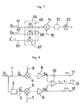
- Fig. 6 is a schematic diagram showing a construction of a CLD in the case where ammonia (hereinafter referred to as NH 3 ) in a stack is measured.
- reference numeral 43 designates a probe comprising a reaction tube 45 (corresponding to the above described treatment portion 3) including a denitrifying catalysis 44 and a reference tube 46 including no denitrifying catalysis 44 provided in a stack (not shown).
- Gas lines 49,50 provided with a convertor 47 for converting NO x and NH 3 , respectively, to NO and a suction pump 48 in series are connected with said reaction tube 45 and said reference tube 46, respectively, and adapted to pass through an electronic cooler 51.
- said gas lines 49, 50 are adapted to correspond to the first sample gas line 1 and the second sample gas line 2, respectively, in Fig. 1.
- Reference numeral 52 designates a zero gas line connected with a zero gas source (not shown).
- gas lines 49, 50 and said zero gas line 52 are connected with an analytic portion 57 in parallel to each other through respective electromagnetic valves 53, 54, 55 (these electro-magnetic valves 53, 54, 55 construct a gas-controlling mechanism 56 in the same manner as the above described electro-magnetic valves 18, 19, 20).
- reference numeral 58 designates an ozone line
- reference numeral 59 designates an ozone-decomposer.
- said signal A is subtracted from said signal B to obtain said concentration of NH 3 .
- a result obtained by subtracting the signal A from a result obtained by adding the signal B to the signal A is multiplied by 1/2 in order to obtain the concentration of NO x .
- reference numeral 64 designates a gas-controlling mechanism for introducing said gas G 1 , G 2 and Z into the analytical portion 14 in the order described at an appointed cycle comprising for example electro-magnetic valves 65, 66, 67 provided in the gas line 61, the gas line 62 and said gas line 63, respectively, and controlledly opened and closed by means of a control mechanism (not shown).
- a control mechanism not shown.
- reference numerals same as those in Fig. 1 designate members same as those in Fig. 1.
- concentration of the same ingredient, for example NO, contained in the sample gas G 1 passing through the first sample gas line 61 and the sample gas G 2 passing through the second sample gas line 62, respectively, can be simultaneously detected by a principle similar to that in the above described CLD shown in Fig. 1.
Landscapes
- Chemical & Material Sciences (AREA)
- Life Sciences & Earth Sciences (AREA)
- Engineering & Computer Science (AREA)
- Health & Medical Sciences (AREA)
- Analytical Chemistry (AREA)
- Food Science & Technology (AREA)
- Medicinal Chemistry (AREA)
- Physics & Mathematics (AREA)
- Combustion & Propulsion (AREA)
- Biochemistry (AREA)
- General Health & Medical Sciences (AREA)
- General Physics & Mathematics (AREA)
- Immunology (AREA)
- Pathology (AREA)
- Investigating Or Analysing Materials By Optical Means (AREA)
- Sampling And Sample Adjustment (AREA)
- Investigating Or Analyzing Non-Biological Materials By The Use Of Chemical Means (AREA)
Claims (5)
- Gasanalysator, bei dem eine erste Probengasleitung (1), durch die ein eine Mehrzahl von Bestandteilen enthaltendes Probengas (G), so wie es ist, hindurchströmt, eine zweite Probengasleitung (2), die von der ersten Probengasleitung (1) abzweigt und mit einem Behandlungsteil (3) zur Behandlung eines bestimmten Bestandteils der im Probengas enthaltenen Bestandteile versehen ist, und eine Nullgasleitung (15), durch die ein Nullgas (Z) hindurchströmt, mit einem einzigen Analyseteil (14) verbunden sind, derart, daß sie parallel zueinander liegen, wobei das durch die erste Probengasleitung (1) hindurchströmende Probengas (G) und das durch die zweite Probengasleitung (2) hindurchströmende behandelte Probengas (G') abwechselnd dem Analyseteil (14), getrennt durch das Nullgas (Z), zugeführt werden, und zwar mittels eines Gassteuermechanismus (17), um einen die Konzentrationen der Bestandteile angebenden Ausgang vom Analyseteil (14) in Signale zu unterteilen, und zwar auf der Grundlage einer Mehrzahl von untereinander verschiedenen Modulationsfrequenzen, die jeweils Bezug zum Umschaltzyklus haben, und wobei diese Signale addiert und subtrahiert werden, um die Konzentrationen der im Probengas enthaltenen Bestandteile zu detektieren.
- Gasanalysator, bei dem eine erste Probengasleitung (61) und eine zweite Probengasleitung (62), durch die dieselben Bestandteile enthaltene Probengase (G1, G2), die unabhängig und verschieden voneinander sind, hindurchströmen, und eine Nullgasleitung (63), durch die ein Nullgas (Z) hindurchströmt, mit einem einzigen Analyseteil (14) so verbunden sind, daß sie parallel zueinander liegen, wobei das durch die erste Probengasleitung (61) hindurchströmende Probengas (G1) und das durch die zweite Probengasleitung (62) hindurchströmende Probengas (G2) abwechselnd dem Analyseteil (14), getrennt durch das Nullgas (Z), zugeführt werden, und zwar unter Steuerung eines Gassteuermechanismus (64), um einen die Konzentrationen der Bestandteile angebenden Ausgang vom Analyseteil (14) zu dieser Zeit in Signale zu unterteilen, und zwar auf der Grundlage einer Mehrzahl von sich unterscheidenden Modulationsfrequenzen, die jeweils einen Bezug zum Umschaltzyklus haben, und wobei diese Signale addiert und subtrahiert werden, um die Konzentrationen desselben in den jeweiligen Probengasen vorhandenen Bestandteils zu detektieren.
- Gasanalysator nach Anspruch 1 oder 2, dadurch gekennzeichnet, daß der Ausgang des Analyseteils (14) unter Verwendung von zwei Behandlungsleitungen (25, 26) in die beiden Signale unterteilt wird, und zwar basierend auf einer Mehrzahl von sich unterscheidenden Modulationsfrequenzen, die einen Bezug zum Umschaltzyklus haben, wobei jede der Behandlungsleitungen (25, 26) einen Bandpassfilter (27, 30), eine Synchrondetektorschaltung (28, 31) und eine Verstärkungsregulierschaltung (29, 32) aufweisen.
- Gasanalysator nach einem der Ansprüche 1 bis 3, dadurch gekennzeichnet, daß die Öffnungsperioden des Gassteuermechanismus (17) für das die erste Probengasleitung durchströmende Gas, für das die zweite Probengasleitung durchströmende Gas und für das Nullgas einander gleich sind.
- Gasanalysator nach Anspruch 4, dadurch gekennzeichnet, daß die Periode der Modulationsfrequenz des Bandpassfilters (27, 30) in der ersten Behandlungsleitung (25)/zweiten Behandlungsleitung (26) zweimal/viermal so groß ist wie die Öffnungsperiode des Gassteuermechanismus (17) (Fig.4).
Applications Claiming Priority (2)
| Application Number | Priority Date | Filing Date | Title |
|---|---|---|---|
| JP2188254A JPH0810216B2 (ja) | 1990-07-17 | 1990-07-17 | ガス分析計 |
| JP188254/90 | 1990-07-17 |
Publications (3)
| Publication Number | Publication Date |
|---|---|
| EP0467307A2 EP0467307A2 (de) | 1992-01-22 |
| EP0467307A3 EP0467307A3 (en) | 1992-06-03 |
| EP0467307B1 true EP0467307B1 (de) | 1996-10-09 |
Family
ID=16220473
Family Applications (1)
| Application Number | Title | Priority Date | Filing Date |
|---|---|---|---|
| EP91111870A Expired - Lifetime EP0467307B1 (de) | 1990-07-17 | 1991-07-16 | Gasanalysator |
Country Status (4)
| Country | Link |
|---|---|
| EP (1) | EP0467307B1 (de) |
| JP (1) | JPH0810216B2 (de) |
| AT (1) | ATE144047T1 (de) |
| DE (1) | DE69122564T2 (de) |
Families Citing this family (9)
| Publication number | Priority date | Publication date | Assignee | Title |
|---|---|---|---|---|
| US5115666A (en) * | 1990-02-08 | 1992-05-26 | Sentech Corporation | Method of detecting halogen gas in a liquid |
| JP3325673B2 (ja) * | 1993-10-25 | 2002-09-17 | アークレイ株式会社 | 呼気中の成分濃度補正方法及び呼気分析装置 |
| DE69623553T2 (de) * | 1995-08-31 | 2003-01-09 | New Oji Paper Co., Ltd. | Konzentrationsmessvorrichtung |
| JPH10274630A (ja) * | 1997-03-31 | 1998-10-13 | Ngk Insulators Ltd | 低濃度NOx計測器 |
| US6105416A (en) | 1998-10-16 | 2000-08-22 | Geo-Centers, Inc. | Ethylene monitoring and control system |
| DE102008028682A1 (de) * | 2008-06-17 | 2010-02-25 | Airbus Deutschland Gmbh | Verfahren zum Vermessen von Gaskonzentrationen mittels eines Metalloxid-Gassensors, Sensorvorrichtung zum Durchführen des Verfahrens sowie Verwendung desselben |
| DE102009004278A1 (de) * | 2009-01-05 | 2010-07-15 | Synthesechemie Dr. Penth Gmbh | Messgerät für geringe Kohlenwasserstoffkonzentrationen |
| JP6320748B2 (ja) * | 2013-12-27 | 2018-05-09 | 株式会社堀場製作所 | ガス分析装置 |
| WO2025062997A1 (ja) * | 2023-09-21 | 2025-03-27 | 株式会社堀場製作所 | 分析装置及び分析方法 |
Family Cites Families (5)
| Publication number | Priority date | Publication date | Assignee | Title |
|---|---|---|---|---|
| NL7314801A (nl) * | 1973-10-27 | 1975-04-29 | Philips Nv | Werkwijze voor kwantitatieve analyse. |
| US4316382A (en) * | 1980-07-21 | 1982-02-23 | Hewlett-Packard Company | Detector with intermittent flow |
| US4432226A (en) * | 1982-02-05 | 1984-02-21 | Dempster Philip T | Method and apparatus for measuring gaseous oxygen |
| JPH0548124Y2 (de) * | 1988-06-30 | 1993-12-20 | ||
| US4947339A (en) * | 1988-12-01 | 1990-08-07 | Jan Czekajewski | Method and apparatus for measuring respiration, oxidation and similar interacting between a sample and a selected component of a fluid medium |
-
1990
- 1990-07-17 JP JP2188254A patent/JPH0810216B2/ja not_active Expired - Fee Related
-
1991
- 1991-07-16 AT AT91111870T patent/ATE144047T1/de not_active IP Right Cessation
- 1991-07-16 EP EP91111870A patent/EP0467307B1/de not_active Expired - Lifetime
- 1991-07-16 DE DE69122564T patent/DE69122564T2/de not_active Expired - Fee Related
Also Published As
| Publication number | Publication date |
|---|---|
| DE69122564D1 (de) | 1996-11-14 |
| EP0467307A3 (en) | 1992-06-03 |
| ATE144047T1 (de) | 1996-10-15 |
| DE69122564T2 (de) | 1997-04-17 |
| EP0467307A2 (de) | 1992-01-22 |
| JPH0474963A (ja) | 1992-03-10 |
| JPH0810216B2 (ja) | 1996-01-31 |
Similar Documents
| Publication | Publication Date | Title |
|---|---|---|
| US3967933A (en) | Dual channel nitrogen oxides analyzer | |
| US5753185A (en) | Vehicle emissions testing system | |
| EP0467307B1 (de) | Gasanalysator | |
| US5255072A (en) | Apparatus for analyzing fluid by multi-fluid modulation mode | |
| JP3656231B2 (ja) | 高精度窒素測定用分析システム | |
| JP3024904B2 (ja) | 光学式ガス分析計 | |
| EP0105659B1 (de) | Kohlenmonoxyddetektor | |
| JP2008261865A (ja) | 揮発性有機化合物測定装置 | |
| EP4524549A1 (de) | Infrarotgasanalysator und infrarotgasanalyseverfahren | |
| EP0261452A2 (de) | Gasanalysiervorrichtung | |
| JPS5916665B2 (ja) | 炭化水素測定装置 | |
| EP0319887B1 (de) | Verfahren und Vorrichtung zur Analysierung von Flüssigkeiten mittels Mehrflüssigkeitenmodulationsverfahren | |
| US5823044A (en) | Method for selective gas sensors based on nonlinear gas reactions | |
| JP3853978B2 (ja) | 水質分析計 | |
| US5102806A (en) | Method for analyzing fluid by multi-fluid modulation mode | |
| JPH079397B2 (ja) | 流体分析方法 | |
| JP3113919U (ja) | 揮発性有機化合物測定装置 | |
| JPH11118676A (ja) | ガス分析計 | |
| JPH0431345B2 (de) | ||
| JPH06103264B2 (ja) | ガス分析計 | |
| JP3341680B2 (ja) | 水質分析計 | |
| JP3113931U (ja) | 揮発性有機化合物測定装置 | |
| JP2855830B2 (ja) | 水分及び全有機炭素分析装置 | |
| Breton | Multicomponent analysis using established techniques | |
| JPH0575645U (ja) | N2 oガス分析装置 |
Legal Events
| Date | Code | Title | Description |
|---|---|---|---|
| PUAI | Public reference made under article 153(3) epc to a published international application that has entered the european phase |
Free format text: ORIGINAL CODE: 0009012 |
|
| AK | Designated contracting states |
Kind code of ref document: A2 Designated state(s): AT DE ES FR IT |
|
| PUAL | Search report despatched |
Free format text: ORIGINAL CODE: 0009013 |
|
| AK | Designated contracting states |
Kind code of ref document: A3 Designated state(s): AT DE ES FR IT |
|
| 17P | Request for examination filed |
Effective date: 19920904 |
|
| 17Q | First examination report despatched |
Effective date: 19940726 |
|
| GRAH | Despatch of communication of intention to grant a patent |
Free format text: ORIGINAL CODE: EPIDOS IGRA |
|
| GRAH | Despatch of communication of intention to grant a patent |
Free format text: ORIGINAL CODE: EPIDOS IGRA |
|
| GRAA | (expected) grant |
Free format text: ORIGINAL CODE: 0009210 |
|
| AK | Designated contracting states |
Kind code of ref document: B1 Designated state(s): AT DE ES FR IT |
|
| PG25 | Lapsed in a contracting state [announced via postgrant information from national office to epo] |
Ref country code: IT Free format text: LAPSE BECAUSE OF FAILURE TO SUBMIT A TRANSLATION OF THE DESCRIPTION OR TO PAY THE FEE WITHIN THE PRE;WARNING: LAPSES OF ITALIAN PATENTS WITH EFFECTIVE DATE BEFORE 2007 MAY HAVE OCCURRED AT ANY TIME BEFORE 2007. THE CORRECT EFFECTIVE DATE MAY BE DIFFERENT FROM THE ONE RECORDED.SCRIBED TIME-LIMIT Effective date: 19961009 Ref country code: ES Free format text: THE PATENT HAS BEEN ANNULLED BY A DECISION OF A NATIONAL AUTHORITY Effective date: 19961009 Ref country code: FR Effective date: 19961009 |
|
| REF | Corresponds to: |
Ref document number: 144047 Country of ref document: AT Date of ref document: 19961015 Kind code of ref document: T |
|
| REF | Corresponds to: |
Ref document number: 69122564 Country of ref document: DE Date of ref document: 19961114 |
|
| EN | Fr: translation not filed | ||
| PLBE | No opposition filed within time limit |
Free format text: ORIGINAL CODE: 0009261 |
|
| STAA | Information on the status of an ep patent application or granted ep patent |
Free format text: STATUS: NO OPPOSITION FILED WITHIN TIME LIMIT |
|
| 26N | No opposition filed | ||
| PGFP | Annual fee paid to national office [announced via postgrant information from national office to epo] |
Ref country code: AT Payment date: 20000712 Year of fee payment: 10 |
|
| PGFP | Annual fee paid to national office [announced via postgrant information from national office to epo] |
Ref country code: DE Payment date: 20000717 Year of fee payment: 10 |
|
| PG25 | Lapsed in a contracting state [announced via postgrant information from national office to epo] |
Ref country code: AT Free format text: LAPSE BECAUSE OF NON-PAYMENT OF DUE FEES Effective date: 20010716 |
|
| PG25 | Lapsed in a contracting state [announced via postgrant information from national office to epo] |
Ref country code: DE Free format text: LAPSE BECAUSE OF NON-PAYMENT OF DUE FEES Effective date: 20020501 |