EP0467310A1 - Chasse-neige - Google Patents
Chasse-neige Download PDFInfo
- Publication number
- EP0467310A1 EP0467310A1 EP91111875A EP91111875A EP0467310A1 EP 0467310 A1 EP0467310 A1 EP 0467310A1 EP 91111875 A EP91111875 A EP 91111875A EP 91111875 A EP91111875 A EP 91111875A EP 0467310 A1 EP0467310 A1 EP 0467310A1
- Authority
- EP
- European Patent Office
- Prior art keywords
- swivel
- snow plow
- parallelogram
- wishbone
- plow according
- Prior art date
- Legal status (The legal status is an assumption and is not a legal conclusion. Google has not performed a legal analysis and makes no representation as to the accuracy of the status listed.)
- Granted
Links
Images


Classifications
-
- E—FIXED CONSTRUCTIONS
- E01—CONSTRUCTION OF ROADS, RAILWAYS, OR BRIDGES
- E01H—STREET CLEANING; CLEANING OF PERMANENT WAYS; CLEANING BEACHES; DISPERSING OR PREVENTING FOG IN GENERAL CLEANING STREET OR RAILWAY FURNITURE OR TUNNEL WALLS
- E01H5/00—Removing snow or ice from roads or like surfaces; Grading or roughening snow or ice
- E01H5/04—Apparatus propelled by animal or engine power; Apparatus propelled by hand with driven dislodging or conveying levelling elements, conveying pneumatically for the dislodged material
- E01H5/06—Apparatus propelled by animal or engine power; Apparatus propelled by hand with driven dislodging or conveying levelling elements, conveying pneumatically for the dislodged material dislodging essentially by non-driven elements, e.g. scraper blades, snow-plough blades, scoop blades
Definitions
- the invention relates to a snow plow, the ploughshare of which is suspended on a supporting part about a vertical axis and whose supporting part is connected to a vehicle-side supporting plate by means of a handlebar parallelogram, a hydraulic lifting cylinder being supported between the supporting plate and the supporting part.
- Such snow plows are subject to the requirement that the ploughshare is not only pivotable to the side, so that it can be cleared to either side of the vehicle, but can also swing about a horizontal axis running in the direction of travel, so that it is able to deal with the cross slope of the Adapt the street or follow the street profile.
- it is known to divide the supporting part, on which the ploughshare is suspended, along a vertical plane running transversely to the direction of travel, the ploughshare being connected to a front part and the handlebar parallelogram being connected to a rear part.
- Such a division is complex since, in addition to a swivel axis, it also requires a return device for securing the ploughshare in the raised state.
- Another known attachment device for a ploughshare dispenses with a division of the supporting part to enable a pendulum movement of the ploughshare; instead, all of the handlebars of the handlebar parallelogram are articulated by means of swivel bearings which are designed as ball joints. Since no lateral forces can be absorbed via ball joints, chains extending from the center to both sides are tensioned between the supporting part and the supporting plate, which are alternately loaded under the effect of the lateral forces on tension. With this solution, the stability of the plow suspension is imperfect, since the ploughshare is guided laterally only to the extent that a chain is taut; Especially in the case of changing lateral forces, uncontrolled plow movements occur in the transition phases. In addition, the correct dimensioning of the chain lengths is difficult; chain solutions are also expensive, since only tested safety chains with high tensile strength are suitable.
- the present invention has for its object to provide a structurally simple suspension device for the ploughshare, which ensures precise longitudinal and lateral guidance of the plow, absorbs lateral forces without unstable phases and enables a pendulum movement of the plow share without a separate pendulum device.
- this task is of a generic type
- the handlebars of the handlebar parallelogram each have at least at one articulation end a swivel bearing designed as a ball joint and that a triangular link is provided in one of the two swiveling planes of the handlebar parallelogram or in a plane parallel to it to absorb lateral forces, which has two articulation points on the Has support plate, which are each designed as a pure pivot bearing with a horizontal pivot axis.
- the swivel bearings are aligned on both sides with respect to a common horizontal swivel axis both in the upper and in the lower swivel plane of the handlebar parallelogram. If the wishbone is not arranged in one of the two swivel planes, but in a third plane parallel to the swivel planes, its two swivel bearings arranged on the same side also lie on a common swivel axis.
- the swivel planes are each defined by one or more upper links, which form the upper swivel plane, and one or more links, which form the lower swivel plane.
- the ball joints can be designed in a variety of ways; Classic ball joints with a swivel-mounted ball joint and this comprehensive spherical cap are relatively expensive, but ideally suited; for their lateral support, it may be appropriate to use elastomeric support elements instead of rigid stops, for example in the form of lateral plastic disks, which are attached to the pivot axis of the bearing ball.
- a simpler embodiment of the ball joint can be formed in the combination of a pivot bearing and a pure pivot bearing be, with the bearing axes in a horizontally aligned ploughshare lying in a horizontal plane and perpendicular to each other.
- all other swivel bearings of the parallelogram of the handlebars are each designed as a ball joint.
- This embodiment ensures a kinematically ideal mobility of the ploughshare with regard to its pendulum movement; for cost reasons, however, it would be conceivable that at least one link end is designed as a simple pivot bearing in one or more links.
- a swivel bearing with play must be selected so that a certain movement compensation can be taken over as part of the pendulum movement.
- the wishbone is present in addition to the four links of the link parallelogram; it is preferably arranged in the lower swivel plane of the handlebar parallelogram.
- an arm of the wishbone is formed by a handlebar of the same pivoting plane of the handlebar parallelogram, i.e. this handlebar is articulated on the support plate side with a pure swivel bearing and has a laterally rigid arm which, together with the said control arm, forms the so-called triangular control arm and which, like the said control arm, is likewise articulated on the support plate via a pure swivel bearing.
- the original ball joint on the support plate side of the side link now included in the wishbone is omitted, as is the ball joint on the support part side of the separate wishbone, i.e. overall, it is simpler without having to accept technical disadvantages.
- An advantageous embodiment of the invention further consists in the fact that the wishbone is elastically biased in a direction perpendicular to the pivot plane relative to a link arranged in the same pivot plane of the handlebar parallelogram.
- a tensioning means preferably in the form of a clamp, which is prestressed against an upper and a lower surface of the associated link, results in an effective provision for the pendulum movement as soon as the snow plow is lifted off the ground.
- the contact surfaces of the handlebars pivoted with respect to the clamp are pivoted back into the contact position in which the ploughshare is horizontal.
- the further lifting of the ploughshare is then limited by the fact that a stop for a lower link of the lower pivot level is provided on the support plate to limit the maximum lifting position.
- the lifting cylinder is expedient on the one hand on the wishbone and on the other hand on the top of the supporting part, e.g. attached to a gallows extending the supporting part.
- the lifting cylinder is preferably supported on the one hand on the central link and on the other hand on the underside of the support plate.
- the arrangement of one or more hydraulic deflection cylinders for the lateral adjustment of the snow plow can be simplified.
- a single deflection cylinder is sufficient, which is articulated on the one hand on the back of the ploughshare and on the other hand on one side of the supporting part. This ensures that the lifting cylinder and deflecting cylinder function completely independently of one another, i.e. can be operated completely independently of one another.
- the snow plow suspension according to the invention is possible regardless of the type of snow plow or the suspension of the ploughshare on the support part.
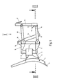
- the snow plow comprises a ploughshare 1 which is articulated on a swivel part 3 by means of short swivel arms 2.
- the tension springs which usually secure the position of the ploughshare 1 with respect to the swivel part 3 and in particular enable their upward deflection when the wear rail 5 of the plow share 1 moves against an obstacle, are omitted.
- the focus here is on the suspension device for the ploughshare, which establishes the connection between a support part 4 and a support plate 6, which has hooks 7 for hanging on a vehicle plate, not shown, attached to the front of the carrier vehicle.
- the swivel part 3 is rotatably connected to a vertical shaft 8; the shaft 8 is pivotally mounted at its opposite ends in a bearing arm 9 of the supporting part 4.
- the ploughshare 1 can be switched between its two clearing positions, which either clear to the right or to the left.
- a (not shown) hydraulic swivel cylinder is used for the changeover, which is supported between the support part 4 on the one hand and the ploughshare 1 or the swivel part 3 on the other hand.
- the height adjustment of the snow plow is the handlebar parallelogram arranged between the support member 4 and the support plate 6.
- only two handlebars can be seen, namely an upper handlebar 10 of the upper pivoting plane of the handlebar parallelogram and a lower handlebar 11 of the lower pivoting plane of the handlebar parallelogram.
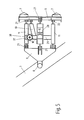
- 2 and 3 there are two upper links 10 and two lower links 11. Each of them is articulated at the ends on the one hand on the support plate 6 and on the other hand on the support part 4.
- a stop 12 is also attached to the support plate 6, the stop surface 13 of which rests on the associated lower link 11 in the maximum stroke position.
- the respective lifting position is secured by a hydraulic lifting cylinder 14, the piston 15 of which is articulated on a boom 16 which extends the support part 4 upwards and the other end of which is articulated on a bearing part 17 which is attached to a wishbone 18 of the lower pivoting plane which is hidden in FIG. 1 is attached.
- the wishbone 18 is clearly visible in the plan view according to FIG. 2. It has two inclined arms 19 converging towards the supporting part 4, which are connected to one another via a cross strut 20.
- the bearing part 17 for the articulation of the lower end of the reciprocating piston 14 is fastened to the cross strut 20.
- both the two upper links 10 and the two lower links 11 are each connected on both sides with ball joints 21 on the supporting part 4 or the supporting plate 6. Both arms 19 of the wishbone 18, however, are articulated on the support plate 6 via pure pivot bearings 22.
- the opposite bearing 23 of the wishbone 18 in the supporting part 4 is, as can be seen in the sectional position according to FIG. 3, designed in the manner of a ball joint, which is composed of a pivot bearing 24 with the bearing pin 25 and a pure pivot bearing 26 with the bearing pin 27.
- the ball joints on the side of the supporting part 4, without exception, both for the articulation of the upper and lower links 10, 11, and the triangular link 18 enable the ploughshare's pendulum movement required for the snow plow support on the road around a horizontal axis running in the clearing direction, i.e. about an axis defined by the journal 25 of the rotary bearing 24.
- a ball joint of conventional design corresponding to the ball joints 21 of the parallelogram link 10, 11, could also be provided.
- the wishbone 18 is articulated on the support plate 6 via pure pivot bearing 22; otherwise the wishbone 18 not fulfilling its task, namely to transfer the high lateral forces of the snow plow into the vehicle suspension.
- pivot bearings are provided in the handlebars 10, 11 of the upper and lower pivoting plane of the handlebar parallelogram, in which the necessary pendulum movement is permitted by rubber sleeves or simply by bearing play.
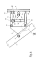
- FIGS. 4 to 6 differs from the embodiment according to FIGS. 1 to 3 essentially by a significant reduction in the number of handlebars.
- the two upper links have been combined into a single central link 28 which is articulated on both sides by means of ball joints 21.
- the lifting cylinder 14 is articulated with its piston 15 directly on the central link 28; the lower end of the cylinder 14 is, as shown in Fig. 6, hinged directly to the support plate 6.
- the wishbone 18 has only one oblique arm 19 which is connected laterally to the lower left link 11 via a cross strut 29. In this way, this handlebar also takes over the tasks of the second arm 19 of the wishbone 18. In this case, however, it is essential that the lower left arm 11 is connected to the support plate 6 via a pure pivot bearing 22.
- a heavy-duty ball joint 30 is provided, which is shown enlarged as detail VII in FIG. 7.
- the hinge point is additionally supported by lateral plastic disks 31, which does not impair the mobility of the bearing, but increases the permissible lateral load capacity.
- FIG. 8 An alternative to FIG. 7 is shown in FIG. 8, wherein a ball joint is shown, which is composed of a pure pivot bearing around the pivot pin 32 and a pure pivot bearing, in which a bushing 33 rotates about a pivot pin 34.
- the cross strut 29 of the wishbone 8 is attached laterally; the handlebar 11 is attached to the rear end of the socket 33.
- a pressure screw 35 serves to axially fix the pivot pin 34 within the bush 33.
- the pivot pin 34 has a recess 36.
- FIG. 9 shows, in an enlarged representation, a reset device 37, the elastomeric compression spring 38 of which is shown in FIGS. 4 to 6.
- This reset device is attached to the cross strut 29 of the wishbone 18. It serves to align the adjacent lower link 11 with respect to the wishbone 18.
- the latter is tensioned by means of a tension spindle 40, the lower end of which is pivotably mounted in a web 41 of the lower bracket part 39 and the upper end of which is braced against a pressure plate 43 by means of a nut 42.
- the pressure plate 43 presses on the upper end of the elastomeric compression spring 38, the lower end of which is supported in relation to the upper clamp part 39.
- the spindle 40 protrudes through a bore 44 in the upper bracket part 39. If the ploughshare is lifted off the ground, the return device 38 effects a horizontal plow position as soon as its lower edge is free from the ground, i.e. an initially existing inclined position of the ploughshare 1 corresponding to its respective pendulum position is eliminated by the prestressing of the compression spring 38, in that the link 11 is forced by the clamp parts 39 to turn back into its starting position.
Landscapes
- Engineering & Computer Science (AREA)
- Architecture (AREA)
- Civil Engineering (AREA)
- Structural Engineering (AREA)
- Automatic Cycles, And Cycles In General (AREA)
- Cleaning Of Streets, Tracks, Or Beaches (AREA)
- Vehicle Body Suspensions (AREA)
Applications Claiming Priority (2)
| Application Number | Priority Date | Filing Date | Title |
|---|---|---|---|
| DE4022683A DE4022683A1 (de) | 1990-07-17 | 1990-07-17 | Schneepflug |
| DE4022683 | 1990-07-17 |
Publications (2)
| Publication Number | Publication Date |
|---|---|
| EP0467310A1 true EP0467310A1 (fr) | 1992-01-22 |
| EP0467310B1 EP0467310B1 (fr) | 1994-06-08 |
Family
ID=6410437
Family Applications (1)
| Application Number | Title | Priority Date | Filing Date |
|---|---|---|---|
| EP91111875A Expired - Lifetime EP0467310B1 (fr) | 1990-07-17 | 1991-07-16 | Chasse-neige |
Country Status (3)
| Country | Link |
|---|---|
| EP (1) | EP0467310B1 (fr) |
| AT (1) | ATE106969T1 (fr) |
| DE (3) | DE4022683A1 (fr) |
Cited By (11)
| Publication number | Priority date | Publication date | Assignee | Title |
|---|---|---|---|---|
| DE4224220A1 (de) * | 1992-07-22 | 1992-12-24 | Beilhack Maschf Martin | Schneepflug |
| DE4205612A1 (de) * | 1992-02-24 | 1993-08-26 | Nusser Josef | Schwenkvorrichtung |
| DE4235839A1 (de) * | 1992-10-23 | 1994-05-05 | Schmidt Winterdienst | Lenkerverbindung |
| DE4414827A1 (de) * | 1994-04-28 | 1995-11-09 | Schmidt Holding Europ Gmbh | Anbauvorrichtung zum Anbau von Geräten, insbesondere Schneeräumgeräten |
| EP1136625A2 (fr) | 2000-03-18 | 2001-09-26 | Schmidt Holding GmbH | Dispositif de support d'accessoires pour un véhicule porteur |
| EP1050626A3 (fr) * | 1999-05-04 | 2002-08-14 | OFFICINE ASSALONI S.r.l. | Dispositif de support et de suspension pour une lame de chasse-neige |
| DE10127874A1 (de) * | 2001-06-08 | 2003-01-02 | Otto Pfau | An einem Fahrzeug fixierbarer Pflug |
| WO2015118499A1 (fr) * | 2014-02-07 | 2015-08-13 | Tokvam As | Dispositif de suspension pour le montage d'un appareil de travail sur un véhicule |
| CN112158780A (zh) * | 2020-09-14 | 2021-01-01 | 王海维 | 一种浮动式升举摆动连接装置 |
| WO2021097574A1 (fr) * | 2019-11-21 | 2021-05-27 | W. Côté Et Fils Ltée. | Chasse-neige pivotant |
| EP4116495A1 (fr) | 2021-07-08 | 2023-01-11 | Aebi Schmidt Deutschland GmbH | Chasse-neige |
Families Citing this family (6)
| Publication number | Priority date | Publication date | Assignee | Title |
|---|---|---|---|---|
| DE4230517C2 (de) * | 1992-09-11 | 1996-05-02 | Beilhack Maschf Martin | Schneepflug |
| DE10023380B4 (de) * | 2000-05-12 | 2007-04-19 | Wiedenmann Gmbh | Räumvorrichtung zum Räumen von unerwünschten Stoffen wie Schnee oder Eis von Verkehrsflächen |
| US9085860B2 (en) | 2012-09-04 | 2015-07-21 | Universal Truck Equipment, Inc. | Wing plow post |
| KR101320903B1 (ko) * | 2013-02-26 | 2013-10-21 | 조상운 | 도로의 제설, 제빙 및 평탄화장치 |
| DE202014004566U1 (de) | 2014-05-30 | 2014-07-16 | Friedrich Ganzmann | Hubvorrichtung zum Ankoppeln an die Wechselvorrichtungen von Hofladern, Frontladern und Dreipunktgestängen zur Erhöhung der Hubhöhe der Arbeitsgeräte |
| US10053826B1 (en) | 2014-12-12 | 2018-08-21 | Alamo Group Inc. | Wing plow apparatus |
Citations (4)
| Publication number | Priority date | Publication date | Assignee | Title |
|---|---|---|---|---|
| EP0111882A2 (fr) * | 1982-12-13 | 1984-06-27 | Ing. Alfred Schmidt Gmbh | Chasse-neige |
| EP0181454A2 (fr) * | 1984-10-27 | 1986-05-21 | Ing. Alfred Schmidt Gmbh | Chasse-neige |
| CH665237A5 (en) * | 1984-05-29 | 1988-04-29 | Viktor Meili Ag Fuer Konstrukt | Bulldozer blade mounting - has double acting rams with linkage on horizontal vehicle axis to blade end hinge |
| EP0362837A2 (fr) * | 1988-10-06 | 1990-04-11 | Ing. Alfred Schmidt Gmbh | Appareil pour l'attelage d'un chasse-neige à un véhicule |
Family Cites Families (5)
| Publication number | Priority date | Publication date | Assignee | Title |
|---|---|---|---|---|
| CH597435A5 (fr) * | 1975-08-05 | 1978-04-14 | Peter Konrad Ag | |
| DK262176A (da) * | 1976-06-11 | 1977-12-12 | Rosenberg & Wiboltt Ro Wi | Redskabsopheng |
| DE3542479A1 (de) * | 1985-11-30 | 1987-06-04 | Beilhack Maschf Martin | Schneepflug |
| DE3602758A1 (de) * | 1986-01-30 | 1987-08-20 | Daimler Benz Ag | Schneepflug |
| DE3790923C2 (de) * | 1987-03-31 | 1994-04-28 | Agency Ind Science Techn | Schneepflug für Fahrzeuge |
-
1990
- 1990-07-17 DE DE4022683A patent/DE4022683A1/de not_active Ceased
-
1991
- 1991-07-16 DE DE9116475U patent/DE9116475U1/de not_active Expired - Lifetime
- 1991-07-16 DE DE59101833T patent/DE59101833D1/de not_active Expired - Fee Related
- 1991-07-16 AT AT91111875T patent/ATE106969T1/de not_active IP Right Cessation
- 1991-07-16 EP EP91111875A patent/EP0467310B1/fr not_active Expired - Lifetime
Patent Citations (4)
| Publication number | Priority date | Publication date | Assignee | Title |
|---|---|---|---|---|
| EP0111882A2 (fr) * | 1982-12-13 | 1984-06-27 | Ing. Alfred Schmidt Gmbh | Chasse-neige |
| CH665237A5 (en) * | 1984-05-29 | 1988-04-29 | Viktor Meili Ag Fuer Konstrukt | Bulldozer blade mounting - has double acting rams with linkage on horizontal vehicle axis to blade end hinge |
| EP0181454A2 (fr) * | 1984-10-27 | 1986-05-21 | Ing. Alfred Schmidt Gmbh | Chasse-neige |
| EP0362837A2 (fr) * | 1988-10-06 | 1990-04-11 | Ing. Alfred Schmidt Gmbh | Appareil pour l'attelage d'un chasse-neige à un véhicule |
Cited By (14)
| Publication number | Priority date | Publication date | Assignee | Title |
|---|---|---|---|---|
| DE4205612A1 (de) * | 1992-02-24 | 1993-08-26 | Nusser Josef | Schwenkvorrichtung |
| DE4224220A1 (de) * | 1992-07-22 | 1992-12-24 | Beilhack Maschf Martin | Schneepflug |
| DE4235839A1 (de) * | 1992-10-23 | 1994-05-05 | Schmidt Winterdienst | Lenkerverbindung |
| DE4414827A1 (de) * | 1994-04-28 | 1995-11-09 | Schmidt Holding Europ Gmbh | Anbauvorrichtung zum Anbau von Geräten, insbesondere Schneeräumgeräten |
| EP1050626A3 (fr) * | 1999-05-04 | 2002-08-14 | OFFICINE ASSALONI S.r.l. | Dispositif de support et de suspension pour une lame de chasse-neige |
| EP1136625A3 (fr) * | 2000-03-18 | 2003-05-28 | Schmidt Holding GmbH | Dispositif de support d'accessoires pour un véhicule porteur |
| EP1136625A2 (fr) | 2000-03-18 | 2001-09-26 | Schmidt Holding GmbH | Dispositif de support d'accessoires pour un véhicule porteur |
| DE10127874A1 (de) * | 2001-06-08 | 2003-01-02 | Otto Pfau | An einem Fahrzeug fixierbarer Pflug |
| WO2015118499A1 (fr) * | 2014-02-07 | 2015-08-13 | Tokvam As | Dispositif de suspension pour le montage d'un appareil de travail sur un véhicule |
| NO340611B1 (no) * | 2014-02-07 | 2017-05-15 | Tokvam As | Kjøretøyoppheng for arbeidsredskap |
| WO2021097574A1 (fr) * | 2019-11-21 | 2021-05-27 | W. Côté Et Fils Ltée. | Chasse-neige pivotant |
| CN112158780A (zh) * | 2020-09-14 | 2021-01-01 | 王海维 | 一种浮动式升举摆动连接装置 |
| EP4116495A1 (fr) | 2021-07-08 | 2023-01-11 | Aebi Schmidt Deutschland GmbH | Chasse-neige |
| DE102021117632A1 (de) | 2021-07-08 | 2023-01-12 | Aebi Schmidt Deutschland Gmbh | Schneepflug |
Also Published As
| Publication number | Publication date |
|---|---|
| DE9116475U1 (de) | 1992-12-10 |
| EP0467310B1 (fr) | 1994-06-08 |
| DE4022683A1 (de) | 1992-01-23 |
| ATE106969T1 (de) | 1994-06-15 |
| DE59101833D1 (de) | 1994-07-14 |
Similar Documents
| Publication | Publication Date | Title |
|---|---|---|
| EP0467310B1 (fr) | Chasse-neige | |
| DE3500529C2 (fr) | ||
| DE3826930C2 (de) | Radaufhängungssystem | |
| EP1302342B1 (fr) | Système de suspension d'un essieu oscillant | |
| DE2018902A1 (de) | Vorrichtung zur federnden Aufhängung einer Mähdrescherplattform | |
| DE4210532C2 (de) | Spurbreitenveränderliches Fahrwerk | |
| EP1525784B1 (fr) | Epandeur agricole | |
| EP1516965B1 (fr) | Dispositif de balayage pour une balayeuse | |
| EP0373148A1 (fr) | Pelle hydraulique | |
| DE4230517C2 (de) | Schneepflug | |
| DE4100669C2 (de) | Trapezträger zum Anbringen an einem Tragrahmen eines landwirtschaftlichen Geräts oder Fahrzeugs | |
| CH665237A5 (en) | Bulldozer blade mounting - has double acting rams with linkage on horizontal vehicle axis to blade end hinge | |
| DE2633428A1 (de) | Anbauvorrichtung zum anbau von geraeten, insbesondere schneeraeumgeraeten | |
| DE2260984A1 (de) | Vorrichtung zur befestigung eines auslegers an einem strassenfahrzeug | |
| DE69613478T2 (de) | Achsenkonstruktion für ein fahrzeug | |
| EP0361008B1 (fr) | Plate-forme de hayon de véhicule | |
| DE102004052760A1 (de) | Tragvorrichtung für die Aufhängung eines Walzenbesens an einem Kehrfahrzeug | |
| DE2206176C3 (de) | Tellerbesenaufhängung an einer Straßenkehrmaschine | |
| DE2219575C3 (de) | Fahrerhaus für Nutzfahrzeuge | |
| EP0557763A2 (fr) | Machine de fraisage | |
| EP0461386B1 (fr) | Dispositif de pivotement pour une machine agricole attelable à l'accouplement à trois points d'un tracteur | |
| EP0392380B1 (fr) | Dispositif de soulèvement d'un essieu suiveur d'un train de roulement à deux essieux d'un véhicule utilitaire | |
| DE3319157A1 (de) | Schleppvorrichtung fuer ein abschleppfahrzeug | |
| DE2727298C2 (de) | Sattelkupplung für Kraftfahrzeuge | |
| DE602004002424T2 (de) | Vorrichtung zur Bedienung eines Spannrads eines Raupenfahrzeugs |
Legal Events
| Date | Code | Title | Description |
|---|---|---|---|
| PUAI | Public reference made under article 153(3) epc to a published international application that has entered the european phase |
Free format text: ORIGINAL CODE: 0009012 |
|
| AK | Designated contracting states |
Kind code of ref document: A1 Designated state(s): AT CH DE FR IT LI |
|
| 17P | Request for examination filed |
Effective date: 19920604 |
|
| 17Q | First examination report despatched |
Effective date: 19930216 |
|
| GRAA | (expected) grant |
Free format text: ORIGINAL CODE: 0009210 |
|
| AK | Designated contracting states |
Kind code of ref document: B1 Designated state(s): AT CH DE FR IT LI |
|
| REF | Corresponds to: |
Ref document number: 106969 Country of ref document: AT Date of ref document: 19940615 Kind code of ref document: T |
|
| ITF | It: translation for a ep patent filed | ||
| REF | Corresponds to: |
Ref document number: 59101833 Country of ref document: DE Date of ref document: 19940714 |
|
| ET | Fr: translation filed | ||
| PLBE | No opposition filed within time limit |
Free format text: ORIGINAL CODE: 0009261 |
|
| STAA | Information on the status of an ep patent application or granted ep patent |
Free format text: STATUS: NO OPPOSITION FILED WITHIN TIME LIMIT |
|
| 26N | No opposition filed | ||
| PGFP | Annual fee paid to national office [announced via postgrant information from national office to epo] |
Ref country code: AT Payment date: 20050523 Year of fee payment: 15 |
|
| PGFP | Annual fee paid to national office [announced via postgrant information from national office to epo] |
Ref country code: FR Payment date: 20050719 Year of fee payment: 15 |
|
| PG25 | Lapsed in a contracting state [announced via postgrant information from national office to epo] |
Ref country code: AT Free format text: LAPSE BECAUSE OF NON-PAYMENT OF DUE FEES Effective date: 20060716 |
|
| REG | Reference to a national code |
Ref country code: FR Ref legal event code: ST Effective date: 20070330 |
|
| REG | Reference to a national code |
Ref country code: CH Ref legal event code: PCAR Free format text: ISLER & PEDRAZZINI AG;POSTFACH 1772;8027 ZUERICH (CH) |
|
| PG25 | Lapsed in a contracting state [announced via postgrant information from national office to epo] |
Ref country code: FR Free format text: LAPSE BECAUSE OF NON-PAYMENT OF DUE FEES Effective date: 20060731 |
|
| PGFP | Annual fee paid to national office [announced via postgrant information from national office to epo] |
Ref country code: CH Payment date: 20090727 Year of fee payment: 19 |
|
| PGFP | Annual fee paid to national office [announced via postgrant information from national office to epo] |
Ref country code: DE Payment date: 20090925 Year of fee payment: 19 |
|
| PGFP | Annual fee paid to national office [announced via postgrant information from national office to epo] |
Ref country code: IT Payment date: 20090727 Year of fee payment: 19 |
|
| REG | Reference to a national code |
Ref country code: CH Ref legal event code: PL |
|
| PG25 | Lapsed in a contracting state [announced via postgrant information from national office to epo] |
Ref country code: CH Free format text: LAPSE BECAUSE OF NON-PAYMENT OF DUE FEES Effective date: 20100731 Ref country code: DE Free format text: LAPSE BECAUSE OF NON-PAYMENT OF DUE FEES Effective date: 20110201 Ref country code: LI Free format text: LAPSE BECAUSE OF NON-PAYMENT OF DUE FEES Effective date: 20100731 |
|
| REG | Reference to a national code |
Ref country code: DE Ref legal event code: R119 Ref document number: 59101833 Country of ref document: DE Effective date: 20110201 |
|
| PG25 | Lapsed in a contracting state [announced via postgrant information from national office to epo] |
Ref country code: IT Free format text: LAPSE BECAUSE OF NON-PAYMENT OF DUE FEES Effective date: 20100716 |