EP0467322A2 - Procédé et dispositif pour l'emballage continu de bouteilles ou objets similaires dans des sachets d'emballage - Google Patents
Procédé et dispositif pour l'emballage continu de bouteilles ou objets similaires dans des sachets d'emballage Download PDFInfo
- Publication number
- EP0467322A2 EP0467322A2 EP91111926A EP91111926A EP0467322A2 EP 0467322 A2 EP0467322 A2 EP 0467322A2 EP 91111926 A EP91111926 A EP 91111926A EP 91111926 A EP91111926 A EP 91111926A EP 0467322 A2 EP0467322 A2 EP 0467322A2
- Authority
- EP
- European Patent Office
- Prior art keywords
- cutting
- film sheet
- packaging bag
- heat sealing
- cylindrical film
- Prior art date
- Legal status (The legal status is an assumption and is not a legal conclusion. Google has not performed a legal analysis and makes no representation as to the accuracy of the status listed.)
- Ceased
Links
Images


Classifications
-
- B—PERFORMING OPERATIONS; TRANSPORTING
- B31—MAKING ARTICLES OF PAPER, CARDBOARD OR MATERIAL WORKED IN A MANNER ANALOGOUS TO PAPER; WORKING PAPER, CARDBOARD OR MATERIAL WORKED IN A MANNER ANALOGOUS TO PAPER
- B31B—MAKING CONTAINERS OF PAPER, CARDBOARD OR MATERIAL WORKED IN A MANNER ANALOGOUS TO PAPER
- B31B50/00—Making rigid or semi-rigid containers, e.g. boxes or cartons
-
- B—PERFORMING OPERATIONS; TRANSPORTING
- B65—CONVEYING; PACKING; STORING; HANDLING THIN OR FILAMENTARY MATERIAL
- B65B—MACHINES, APPARATUS OR DEVICES FOR, OR METHODS OF, PACKAGING ARTICLES OR MATERIALS; UNPACKING
- B65B21/00—Packaging or unpacking of bottles
- B65B21/24—Enclosing bottles in wrappers
- B65B21/245—Enclosing bottles in wrappers in flexible wrappers, e.g. foils
-
- B—PERFORMING OPERATIONS; TRANSPORTING
- B31—MAKING ARTICLES OF PAPER, CARDBOARD OR MATERIAL WORKED IN A MANNER ANALOGOUS TO PAPER; WORKING PAPER, CARDBOARD OR MATERIAL WORKED IN A MANNER ANALOGOUS TO PAPER
- B31B—MAKING CONTAINERS OF PAPER, CARDBOARD OR MATERIAL WORKED IN A MANNER ANALOGOUS TO PAPER
- B31B70/00—Making flexible containers, e.g. envelopes or bags
-
- B—PERFORMING OPERATIONS; TRANSPORTING
- B65—CONVEYING; PACKING; STORING; HANDLING THIN OR FILAMENTARY MATERIAL
- B65B—MACHINES, APPARATUS OR DEVICES FOR, OR METHODS OF, PACKAGING ARTICLES OR MATERIALS; UNPACKING
- B65B9/00—Enclosing successive articles, or quantities of material, e.g. liquids or semiliquids, in flat, folded, or tubular webs of flexible sheet material; Subdividing filled flexible tubes to form packages
- B65B9/10—Enclosing successive articles, or quantities of material, in preformed tubular webs, or in webs formed into tubes around filling nozzles, e.g. extruded tubular webs
- B65B9/13—Enclosing successive articles, or quantities of material, in preformed tubular webs, or in webs formed into tubes around filling nozzles, e.g. extruded tubular webs the preformed tubular webs being supplied in a flattened state
-
- B—PERFORMING OPERATIONS; TRANSPORTING
- B31—MAKING ARTICLES OF PAPER, CARDBOARD OR MATERIAL WORKED IN A MANNER ANALOGOUS TO PAPER; WORKING PAPER, CARDBOARD OR MATERIAL WORKED IN A MANNER ANALOGOUS TO PAPER
- B31B—MAKING CONTAINERS OF PAPER, CARDBOARD OR MATERIAL WORKED IN A MANNER ANALOGOUS TO PAPER
- B31B2155/00—Flexible containers made from webs
- B31B2155/003—Flexible containers made from webs starting from tubular webs
-
- B—PERFORMING OPERATIONS; TRANSPORTING
- B31—MAKING ARTICLES OF PAPER, CARDBOARD OR MATERIAL WORKED IN A MANNER ANALOGOUS TO PAPER; WORKING PAPER, CARDBOARD OR MATERIAL WORKED IN A MANNER ANALOGOUS TO PAPER
- B31B—MAKING CONTAINERS OF PAPER, CARDBOARD OR MATERIAL WORKED IN A MANNER ANALOGOUS TO PAPER
- B31B2160/00—Shape of flexible containers
- B31B2160/10—Shape of flexible containers rectangular and flat, i.e. without structural provision for thickness of contents
Definitions
- the present invention relates to novel methods of preparation of packaging bags for bottle by utilizing heat shrinking film, novel methods of preparation of packaging bottles and novel apparatus utilized therefore.
- the present invention relates to methods of continuous preparation of packaging bags for bottles made of heat shrinking film sheet which is fitted over the top of a bottle having a narrow opening at the top and allowed to heat shrink by heating to make a packaging bottle fitted tightly in the shape of the bottle with the packaging bag by the shrinking force of the bag and an apparatus utilized therefor.
- the present invention also relates to methods of preparation of packaging bottles which comprise fitting a packaging bag made of heat shrinking film sheet over the top of a bottle having a narrow opening at the top and heat shrinking the packaging bag by heating to make a packaging bottle fitted tightly in the shape of the bottle with the packaging bag by the action of the shrinking force of the bag and an apparatus utilized therefor.
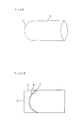
- Packaging bottles having heat shrinking film can be prepared by fitting a bag made of film formed by closing an end of cylindrical film by heat sealing, such as shown in Fig. 9, over a bottle and then by heat shrinking by heating to make a tightly fitted film over the outside of the bottle in the shape of the bottle.
- the closed end of the packaging bag is made into a shape of arch as shown in Fig. 9 to make the packaging film fit tightly in the shape of the cap of the bottle after heat shrinking. If the closed end of the packaging bag has a shape of straight line, the film sheet at the corners of the closed end do not fit tightly to the shape of the cap of the bottle but remain separated from the face of the bottle.
- the packaging bag having the closed end of arch shape as shown in Fig. 9 shrinks to the same shape as the bottle.
- the cap of the bottle is fixed by the shrinking action of the packaging bag and this condition makes so called virgin seal.
- the marks and labels are easily placed on the face of the packaging bottle even when printing is not possible on the bare face of the bottle.
- Packaging bottles fitted with heat shrinking film are generally prepared by the following method: a number of packaging bags attached with a scrap piece S to each of the bags are prepared by heat sealing the closing end T of the packaging bags in a shape of arch as shown in Fig. 10; after the packaging bags thus prepared are stacked, scrap pieces S are discharged manually; the remaining packaging bags R as shown in Fig. 9 are stored once in a bag supply box of a packaging machine in the form of stacked bags; the packaging bag is taken out one by one to a packaging table and placed over the outside of a bottle; and then the packaging bag is allowed to shrink by heating to prepare a packaging bottle fitted with the bag.
- the conventional method described above has problems that efficiency of the operation is low because manual operations are included during the process and also because blocking and letting air out of a bag are not easily made and that the number of deficient packaging, such as misplaced printing and uneven shrinking of the film, is increased because the packaging bag makes erroneous movement from the correct position during shrinking.
- the conventional method described above has another problem that automatic continuous fitting of the packaging bag to the bottle cannot be smoothly operated in spite of numerous trials for the purpose. This problem arises because the diameter of the packaging bag cannot be made much larger than the diameter of the bottle to achieve good fitting of the film to the bottle by heat shrinking.
- the scrap piece S can be easily handled and smoothly discharged to the outside of the preparation process when the long cylindrical film sheet is fed to the apparatus so as to place the portion of the film sheet which is to form the open end of the packaging bag at the top, the both ends of the scrap piece shown by a straight line A and a curved line B in Fig. 5 are cut off approximately simultaneously and the scrap pieces are removed from the both ends of the film sheet approximately simultaneously.
- the scrap piece S can be removed from the end of the film sheet by cutting only the straight line portion A of Fig. 6. It was also discovered that the preparation of the packaging bag is performed efficiently by cutting the scrap piece S and the peripheral part of the closed end of the packaging bag approximately simultaneously.
- the present invention comprises following inventions:
- the heat shrinking packaging bag utilized in the invention is a cylindrical film sheet in which one of the two ends is closed by heat sealing and the closed end is formed to a curved shape like an arch.
- a suitable shape of the arch is selected according to the shape of the bottle to which the packaging bag is fitted.
- film sheet at the comers of the packaging bag should not be left separated from the face of the bottle but should be tightly fitted all around.
- a shape of arch satisfying this condition can be utilized as the shape of arch in the invention.
- coefficient of heat shrinkage of the film utilized in the invention is not particularly limited. Suitable films can generally be selected from films having coefficient of heat shrinkage in the range from 5 to 85%, preferably in the range from 10 to 50% and utilized in the invention.
- Thickness of the film utilized in the invention is not particularly limited but can be suitably selected according to requirements for properties. Films having the thickness in the range from 10 to 100 /1.m are generally utilized and films having the thickness in the range 10 to 50 /1.m are preferably utilized in the invention.
- Shape and size of the bottles utilized in the invention are not particularly limited. Narrow neck bottles having section of approximately circular shape or approximately elliptical shape are preferably utilized. Examples of such bottles are bottles utilized for containing toiletries, foods, detergents and the like other commercial products.
- Material of the bottles utilized in the invention is not particularly limited. Bottles made of plastics, glass, metal, paper, composites of these materials and like other materials can be utilized.
- the end part of the long cylindrical film sheet made of heat shrinking film has a length approximately the same with the length of unit to be cut off.
- the length of feeding of the long cylindrical film sheet made of heat shrinking film at one time is exactly the same as the length of unit to be cut off.
- the end part of the long cylindrical film sheet made of heat shrinking film is the open end of the packaging bag in one case and the scrap piece in the other case.
- the end part of the long cylindrical film sheet is fed to the cutting and heat sealing table in the apparatus of preparation of packaging bags for bottles, the end part is fixed to the table by zigs for fixing film sheet.
- the cutting and heat sealing table may be placed either horizontally or vertically.
- a heat sealing blade of arch shape and a cutting blade of straight shape which work in a synchronized action with the action of feeding of the long cylindrical film sheet are fixed at the positions above the table.
- the long cylindrical film sheet can be heat sealed and cut by pressing the heat sealing blade of arch shape against the face of the long cylindrical film sheet. It is preferable for the purpose of easier operation of cutting that the scrap piece formed is moved away from the heat sealed part after the heat sealing is done.
- various methods can be utilized, such as moving the scrap piece away by holding the scrap piece by a holding device.
- the scrap piece can be moved to various directions. It is preferable that the scrap piece is moved to the direction perpendicular to the line of heat sealing because it makes the operation of cutting off of the scrap piece easier.
- the heat sealing blade of arch shape and the cutting blade of straight shape are preferably fixed to a sliding block faced to the cutting and heat sealing table in positions which make the tips of the heat sealing blade and the cutting blade lie in approximately the same plane so that the cuttings can be done approximately simultaneously.
- the closing end of the packaging bag to be prepared is heat sealed by the heat sealing blade of arch shape, the periphery of the closed end is cut off and the open end of the next packaging bag is formed by cutting the long cylindrical film sheet by the cutting blade of straight shape.
- the scrap piece separated from the cylindrical film sheet can be discharged from the cutting and heat sealing table in a synchronized action with the action of cutting operation of the sliding block. This operation is preferred because the scrap piece can be discharged from the table by either suction or blowing of air and like other methods.
- Means of discharging the scrap piece from the table works immediately after the operation of cutting in a synchronized action with the action of the cutting.
- the operation of cutting the peripheral part of the heat sealed part may be done by a cutting blade of arch shape fixed at a position parallel to the heat sealing blade of arch shape.
- the heat sealing blade of arch shape works as the tool for heat sealing alone and does not work as the tool for cutting.
- the cutting blade of arch shape and the cutting blade of straight shape are preferably fixed to a sliding block faced to the cutting and heat sealing table in positions which make the tips of the heat sealing blade and the cutting blade lie in approximately the same plane so that the cuttings can be done approximately simultaneously.
- the method in which both of the heat sealing and the cutting are made by the heat sealing blade of arch shape alone is more suitable for film sheet of polyvinyl chloride.
- the method in which the heat sealing is made by the heat sealing blade of arch shape and the cutting is made by the cutting blade of arch shape is more suitable for film sheet of polyethylene terephthalate and film sheet of polypropylene.
- the end part of the long cylindrical film sheet is fed to the cutting and heat sealing table in the apparatus of preparation of packaging bags for bottles, the end part is fixed to the table by zigs for fixing film sheet.
- the cutting and heat sealing table may be placed either horizontally or vertically.
- the scrap piece at the end of the long cylindrical film sheet is cut off by pressing the cutting blade of straight shape against the face of the film sheet.
- the scrap piece cut off is discharged from the cutting and heat sealing table by a suitable method, such as by the action of suction or blowing of air.
- the heat sealing blade of arch shape and the cutting blade of straight shape move by sliding in a synchronized action with the feeding of the long cylindrical film sheet and heat seal, melt cut and cut the cylindrical film sheet by pressing against the film sheet.
- Another feature of the method of preparation of packaging bottles of the invention is the method of widely opening the open end of the packaging bag prepared above, fitting a bottle to the bag and allowing heat shrinking of the bag.
- the open end of the packaging bag As the method of widely opening the open end of the packaging bag and the method of fitting a bottle into the bag, all of the generally known methods in the preparation of bags can be utilized. It is preferable that the open end of the bag is widely open by the action of vacuum pads attached to both of the upper side and the lower side of the bag and then the bottle is inserted into the bag by inserting the top of the bottle first.
- a vent hole may be made in the bag by using a needle before the process of heat shrinking to remove air trapped inside and to make the bag fit to the face of the bottle more tightly.
- the packaging bottle can be continuously prepared by the methods described above.
- Another feature of the invention is the method of preparation of packaging bottles comprising (A) a process in which the open end of a packaging bag prepared by closing an end of a cylindrical film sheet made of heat shrinking film as the material by melting in an arch shape and leaving the other end of the cylindrical film sheet open is made widely open by pulling from the outside of the cylindrical film sheet by the action of vacuum pads attached to the outside of the cylindrical film sheet, followed by separating the vacuum pads from each other; a flapper is inserted into the open end of the packaging bag; a bottle which is attached at its bottom, by the action of vacuum, to a vacuum pad fixed at the tip of an inserting rod is inserted into the open end of the packaging bag with the inserting rod in a manner that the top of the packaging bottle is inserted first; and the packaging bag is fitted to the outside of the bottle; and (B) a process in which the bottle fitted with the packaging film is heated; the packaging bag fitted to the outside of the bottle is allowed to shrink; and a packaging bottle is prepared.
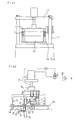
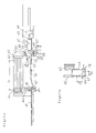
- FIG. 1 and Fig. 2 show an example of the apparatus of the invention.
- This apparatus continuously prepares heat shrinking packaging bags for bottles by processing the end part of the long cylindrical film sheet having the open end at its end, as shown in Fig. 5, by cutting the film sheet to form the open end A of the bag, heat sealing the closed part of arch shape T, cutting periphery of the closed part of arch shape B to form the closed end of the bag, opening a vent hole K, making of perforations M and smooth discharge of a scrap piece S.
- the apparatus of the invention composed mainly of a cutting and heat sealing table 1 having an outlet hole for a scrap piece 2 at the center, a sliding block 9 which moves by sliding in reciprocal movement by the action of a cylinder 5 which is fixed to a pole on the table and a scrap piece receiver 4 placed under the table as a tool for discharging the scrap piece.
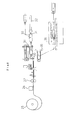
- Fig. 7 Relative positions of the scrap piece receiver 4, the cutting blade of straight shape 7 and the cutting blade of arch shape 8 in relation to the outlet hole at the center of the table 1 are shown in Fig. 7 which is the projection drawing from the upper position.
- the cutting blade of straight shape 7 and the cutting blade arch shape 8 are placed at positions between the edge of the outlet hole 2 and the edge of the scrap piece receiver 4 so that the two blade do not make contact with the table 1.
- the shape of curvature of the edge D is the same as the shape of the curvature of the closing end of the bag T or the cutting blade of arch shape B.
- the distance between the edge C and the edge D of the outlet hole is slightly larger than the width of the scrap piece.
- the distance between the edge E and the edge F of the outlet hole is larger than the width of the cylindrical film sheet.
- a jagged blade 13 for the perforations and a needle 10 for the vent hole are fixed to the sliding block 9.
- the end part of the long cylindrical film sheet is fed to the cutting and heat sealing table 1 intermittently by a generally known method.
- generally known methods are a method utilizing a roll which works periodically for a definite length of time, a method in which a feed pinch roll is stopped by sensing a printed mark on the film sheet by a photoelectric tube, followed by restarting of the feed pinch roll in the action connected with a designated operation and other like methods.
- the length of feeding of the long cylindrical film sheet made of heat shrinking film at one time is exactly the same as the length of unit to be cut off.
- Stoppers for the film sheet 14, 15 and 16 which are placed at three positions, in the front, in the middle and in the rear of the two cutting blades, move downward to the face of the cutting and heat sealing table 1 to fix the film sheet to the table in a synchronized action with the action of feeding of the end part of the long cylindrical film sheet.
- the scrap piece receiver 4 moves upward in a synchronized action with the downward movement of the stopper 15 for the film sheet and the part of the film sheet which is to become the scrap piece is firmly held by the scrap piece receiver 4 and the stopper 15.
- the scrap piece S separated from the film sheet by the cutting operation described above is held by the scrap piece receiver 4 by suction. Then, the scrap piece receiver 4 moves downward when the sliding block 9 moves upward and, when the scrap piece receiver comes to the position of a nozzle for injection of compressed air 6, the suction is stopped and the scrap piece is left free. The scrap piece is then transferred to a scrap piece vessel by the injection of air stream through the air injection nozzle 6 and/or the suction hole of the scrap piece receiver. Mechanical transfer of the scrap piece can be utilized in place of the transfer by air injection.
- the scrap piece may be discharged by the action of air stream through the outlet hole of the table 1 to the outside of the apparatus generated by means of a vacuum pump or an air compressor without utilizing suction of the scrap piece receiver.
- the sliding block 9 and the film stoppers 14, 15 and 16 move upward and the packaging bag prepared and the end part of the cylindrical film sheet for the next unit are made free on the table 1.
- the packaging bag prepared is transferred to the next stage of the process.
- the end part of the long cylindrical film sheet for the next unit is fed and the process is repeated all over again.
- movements by generally known driving systems can be utilized.
- upward and downward reciprocal linear movements by a cylinder or reciprocal non-linear movement by a cyclic movement of an arm may be utilized.
- Packaging bags were prepared continuously and smoothly from cylindrical uniaxial oriented film sheet of polyethylene terephthalate having thickness of 25 /1.m and coefficient of shrinkage of 15% parallel to the direction of drawing and 35 % perpendicular to the direction of drawing by utilizing the apparatus of the invention.
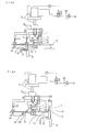
- Fig. 3 shows another example of the apparatus of the invention. This apparatus is similar to the apparatus shown in Fig. 2 but different in that this apparatus does not have a cutting blade of arch shape.
- the tip of the heat sealing blade of arch shape 3 is fixed to the sliding block 9 at a position slightly higher than the position of the tip of the cutting blade of straight shape.
- the sliding block 9 moves vertically by the action of reciprocal movement of cylinder 5.
- the tip of the heat sealing blade of arch shape 3 is in contact with the face of the cutting and heat sealing table 1 and the tip of the cutting blade of straight shape is in a position passing through the surface of table 1 at the edge of the outlet hole at the center of the table.
- Stoppers for the film sheet 14, 15 and 16 which are placed at three positions, in the front, in the middle and in the rear of the heat sealing blade of arch shape and the cutting blade of straight shape, move downward to the face of the table 1 to fix the film sheet to the table in a synchronized action with the action of feeding of the end part of the long cylindrical film sheet.
- the scrap piece receiver 4 moves upward in a synchronized action with the downward movement of the stopper for the film sheet 15 and the part of the film sheet which is to become the scrap piece is firmly held by the scrap piece receiver 4 and the stopper 15.
- the sliding block 9 moves downward in an action slightly delayed from the downward movement of the stoppers for the film sheet.
- the cutting blade of straight shape 7 cuts the cylindrical film sheet and the heat sealing blade of arch shape 3 heat seals the cylindrical film sheet.
- the tip of the heat sealing blade of arch shape 3 is fixed at a position slightly higher than the tip of the cutting blade of straight shape 7 and the part of the film sheet can be heat sealed approximately simultaneously with the cutting operation of the film sheet by the cutting blade of straight shape.
- a cutting blade of straight shape 7 and a heat sealing blade of arch shape 3 heated by a heater 11 are fixed to the sliding black 9.
- a jagged blade 13 for perforations and a needle 10 for a vent hole are fixed to the sliding block 9 as well as the elements described above.
- the scrap piece S separated from the film sheet by the cutting operation described above is held at the scrap piece receiver 4 by suction.
- the scrap piece receiver 4 moves downward while the sliding block 9 moves upward.
- the suction is stopped and the scrap piece is left free.
- the scrap piece is then transferred to a scrap piece vessel by the injection of air stream through the air injection nozzle 6 and/or the suction hole of the scrap piece receiver. Mechanical transfer of the scrap piece can be utilized in place of the transfer by air injection.
- the heat shrinking cylindrical film sheet is supplied from a roll 25 of the long film sheet at the left.
- the end part of the film sheet is fed intermittently to the cutting and heat sealing table 1 of the apparatus of preparation of packaging bags with a pitch of the designated length of cutting unit.
- the length of cutting unit can be decided according to the size of bottle, the width of scrap piece and other factors.
- the method and apparatus of the invention can be applied to packaging of other vessels as well as the packaging of bottles.
Landscapes
- Engineering & Computer Science (AREA)
- Mechanical Engineering (AREA)
- Auxiliary Devices For And Details Of Packaging Control (AREA)
- Making Paper Articles (AREA)
Applications Claiming Priority (6)
| Application Number | Priority Date | Filing Date | Title |
|---|---|---|---|
| JP19243590A JP2896593B2 (ja) | 1990-07-20 | 1990-07-20 | 包装瓶の製造方法及び包装瓶製造装置 |
| JP02192434A JP3119307B2 (ja) | 1990-07-20 | 1990-07-20 | 包装瓶の製造方法及び包装瓶製造装置 |
| JP192434/90 | 1990-07-20 | ||
| JP192435/90 | 1990-07-20 | ||
| JP2213440A JP2920780B2 (ja) | 1990-08-10 | 1990-08-10 | 瓶用包装袋の製造方法及び該製造方法に用いる装置 |
| JP213440/90 | 1990-08-10 |
Publications (2)
| Publication Number | Publication Date |
|---|---|
| EP0467322A2 true EP0467322A2 (fr) | 1992-01-22 |
| EP0467322A3 EP0467322A3 (en) | 1992-06-03 |
Family
ID=27326612
Family Applications (1)
| Application Number | Title | Priority Date | Filing Date |
|---|---|---|---|
| EP19910111926 Ceased EP0467322A3 (en) | 1990-07-20 | 1991-07-17 | Methods of preparation of packaging bags for bottles, methods of preparation of packaging bottles and apparatus utilized therefor |
Country Status (5)
| Country | Link |
|---|---|
| US (1) | US5179819A (fr) |
| EP (1) | EP0467322A3 (fr) |
| KR (1) | KR920002316A (fr) |
| AU (1) | AU645584B2 (fr) |
| CA (1) | CA2047410A1 (fr) |
Cited By (2)
| Publication number | Priority date | Publication date | Assignee | Title |
|---|---|---|---|---|
| EP0689992A1 (fr) * | 1994-06-27 | 1996-01-03 | Sumitomo Bakelite Company Limited | Procédé et dispositif pour revêtir un récipient avec un film thermoretractable tubulaire |
| CN104890962A (zh) * | 2015-05-15 | 2015-09-09 | 广州市兴世机械制造有限公司 | 一种护垫自动包装生产线设备及其生产工艺 |
Families Citing this family (18)
| Publication number | Priority date | Publication date | Assignee | Title |
|---|---|---|---|---|
| US5590509A (en) * | 1994-03-23 | 1997-01-07 | W. R. Grace & Co-Conn. | Process and machine for conditioning any products in containers such as barquettes |
| US5667071A (en) * | 1994-08-31 | 1997-09-16 | Fuji Photo Film Co., Ltd. | Photosensitive material package and packaging apparatus for the same |
| US5873218A (en) * | 1995-03-31 | 1999-02-23 | E. I. Du Pont De Nemours And Company | Packaging system capable of venting steam while remaining tamper resistant and methods relating thereto |
| DE19531717A1 (de) * | 1995-08-29 | 1997-03-06 | Willy Dipl Ing Bartels | Verfahren zur Herstellung von Kunststoff-Umverpackungen |
| US5970688A (en) * | 1998-01-28 | 1999-10-26 | Ethicon, Inc. | Apparatus for opening pouches for insertion of objects thereinto |
| NZ329864A (en) * | 1998-02-27 | 1998-09-24 | Equipment Technology Ltd | Packaging apparatus with bag fitted over mouth of station where product is ejected horizontally into bag |
| IT246650Y1 (it) * | 1999-04-15 | 2002-04-09 | Minipack Torre Spa | Macchina confezionatrice a tunnel per l'impaccamento con film termoretraibile |
| US7980047B1 (en) * | 2000-07-12 | 2011-07-19 | S.C. Johnson & Son, Inc. | Apparatus for and method of severing and sealing thermoplastic film |
| EP1397262B1 (fr) * | 2001-05-31 | 2013-03-06 | Compagnie Generale Des Etablissements Michelin | Renforcement de flanc d'un pneumatique radial |
| DE102004049480A1 (de) * | 2004-09-30 | 2006-04-13 | Steinkrug Gmbh & Co. Kg | Verfahren und Vorrichtung zum Verpacken von Lebensmittelkörpern mit einer Endlosschlauchfolie |
| US7832553B2 (en) * | 2006-03-17 | 2010-11-16 | Illinois Tool Works Inc. | Heat-shrinkable holder for articles, heat-shrinkable package of articles, heat-shrinkable sleeve for articles, and method and device for packaging and sleeving articles |
| BRPI0721122B1 (pt) * | 2006-12-15 | 2019-02-19 | Ccl Label Gmbh | Aplicador de rótulo de capa de película extensível |
| CN104015949A (zh) * | 2014-06-09 | 2014-09-03 | 烟台三柱电子有限公司 | 一种电源适配器后整理生产线 |
| BR102014030315B1 (pt) * | 2014-12-04 | 2021-09-08 | Ball Beverage Can South America S/A | Processo de embalagem de um conjunto de tampas empilhadas e dispositivo de embalagem para conjuntos de tampas empilhadas |
| WO2022168350A1 (fr) * | 2021-02-03 | 2022-08-11 | 株式会社Pfu | Dispositif de reconnaissance d'objet, et dispositif de traitement d'objet |
| CN115180200A (zh) * | 2021-04-02 | 2022-10-14 | 泰连服务有限公司 | 零件包装系统和方法 |
| US20250196387A1 (en) | 2023-12-14 | 2025-06-19 | Axon Llc | Machine and method for applying tubular shrink sleeve material to objects |
| CN117864536A (zh) * | 2024-03-07 | 2024-04-12 | 常州福斯智能科技有限公司 | 一种车灯驱动控制器加工用包装设备的使用方法 |
Family Cites Families (10)
| Publication number | Priority date | Publication date | Assignee | Title |
|---|---|---|---|---|
| US2800163A (en) * | 1955-12-28 | 1957-07-23 | Milprint Inc | Method and apparatus for producing flexible containers |
| US3053723A (en) * | 1958-05-29 | 1962-09-11 | Union Carbide Corp | Article fabricating apparatus and method |
| DE1223739B (de) * | 1962-09-20 | 1966-08-25 | Anton Uebelher | Vorrichtung an Verpackungsmaschinen |
| US3558406A (en) * | 1967-10-23 | 1971-01-26 | Emanuel Kugler | Bottom seal contour bag manufacture |
| US3579948A (en) * | 1968-04-29 | 1971-05-25 | Automated Packaging Corp | Bag handling apparatus and method |
| DE6752577U (de) * | 1968-08-09 | 1970-01-22 | Claus Wolfgang Hartmann | Vorrichtung zum verpacken eines verpackungskoerpers. |
| US4016706A (en) * | 1976-03-31 | 1977-04-12 | Owens-Illinois, Inc. | Method of controlling shrinkage of a sleeve wrap on a container |
| JPS5623423A (en) * | 1979-08-06 | 1981-03-05 | Kureha Chemical Ind Co Ltd | Vacuum packing method for solid body |
| US4730437A (en) * | 1987-05-13 | 1988-03-15 | Benno Edward L | Packaging method and machine |
| US4765121A (en) * | 1987-05-22 | 1988-08-23 | Pdc International Corporation | Banding apparatus with floating mandrel |
-
1991
- 1991-07-15 US US07/729,936 patent/US5179819A/en not_active Expired - Fee Related
- 1991-07-17 EP EP19910111926 patent/EP0467322A3/en not_active Ceased
- 1991-07-18 AU AU81108/91A patent/AU645584B2/en not_active Ceased
- 1991-07-19 CA CA002047410A patent/CA2047410A1/fr not_active Abandoned
- 1991-07-20 KR KR1019910012463A patent/KR920002316A/ko not_active Withdrawn
Cited By (2)
| Publication number | Priority date | Publication date | Assignee | Title |
|---|---|---|---|---|
| EP0689992A1 (fr) * | 1994-06-27 | 1996-01-03 | Sumitomo Bakelite Company Limited | Procédé et dispositif pour revêtir un récipient avec un film thermoretractable tubulaire |
| CN104890962A (zh) * | 2015-05-15 | 2015-09-09 | 广州市兴世机械制造有限公司 | 一种护垫自动包装生产线设备及其生产工艺 |
Also Published As
| Publication number | Publication date |
|---|---|
| AU645584B2 (en) | 1994-01-20 |
| EP0467322A3 (en) | 1992-06-03 |
| CA2047410A1 (fr) | 1992-01-21 |
| US5179819A (en) | 1993-01-19 |
| AU8110891A (en) | 1992-01-23 |
| KR920002316A (ko) | 1992-02-28 |
Similar Documents
| Publication | Publication Date | Title |
|---|---|---|
| US5179819A (en) | Methods of preparation of packaging bags for bottles, methods of preparation of packaging bottles and apparatus utilized therefor | |
| EP0150689B1 (fr) | Procédé et appareil pour emballer des articles d'une forme quelconque dans une pellicule extensible en matière plastique | |
| US4800708A (en) | Apparatus and method for forming foam cushions for packaging purposes | |
| EP0688720B1 (fr) | Procédé et appareil pour la fabrication d'un réceptacle avec une étiquette tubulaire | |
| US2800163A (en) | Method and apparatus for producing flexible containers | |
| EP0539800B1 (fr) | Procédé et dispositif pour la fabrication continue de sacs | |
| US9272804B2 (en) | Bundle unwrapping machine | |
| US4562688A (en) | Apparatus and method for applying heat-shrinkable members to containers | |
| EP0689992A1 (fr) | Procédé et dispositif pour revêtir un récipient avec un film thermoretractable tubulaire | |
| CN101405188A (zh) | 用于吹制成型和热焊接容器的改进的热成型设备 | |
| KR102530698B1 (ko) | 페트병 분리수거를 위한 라벨제거장치 | |
| US4730439A (en) | Method and apparatus for packaging a product in individual vacuum sealed packets | |
| WO1998021096A1 (fr) | Dispositif de fermeture hermetique pour appareil d'emballage | |
| JP2784698B2 (ja) | 瓶用包装袋及び包装瓶の製造方法及びその製造装置 | |
| US4294058A (en) | Container package and its manufacture | |
| JP2896593B2 (ja) | 包装瓶の製造方法及び包装瓶製造装置 | |
| JP3388888B2 (ja) | 筒状熱収縮性フイルムを装着した容器の製造方法及び該容器の製造装置 | |
| CN216507046U (zh) | 一种保鲜袋折叠机 | |
| JP2920780B2 (ja) | 瓶用包装袋の製造方法及び該製造方法に用いる装置 | |
| JP3108655B2 (ja) | ペットボトル回収処理装置 | |
| JP3119307B2 (ja) | 包装瓶の製造方法及び包装瓶製造装置 | |
| KR102924184B1 (ko) | 수액용기 제조장치 | |
| JPH0333575B2 (fr) | ||
| JPH08151020A (ja) | 包装体の製造方法 | |
| EP0111925A2 (fr) | Pièce thermorétractable formée par enroulement hélicoidal, procédé et appareil pour sa fabrication et procédé et appareil pour son application sur un récipient |
Legal Events
| Date | Code | Title | Description |
|---|---|---|---|
| PUAI | Public reference made under article 153(3) epc to a published international application that has entered the european phase |
Free format text: ORIGINAL CODE: 0009012 |
|
| AK | Designated contracting states |
Kind code of ref document: A2 Designated state(s): DE FR GB IT NL SE |
|
| PUAL | Search report despatched |
Free format text: ORIGINAL CODE: 0009013 |
|
| AK | Designated contracting states |
Kind code of ref document: A3 Designated state(s): DE FR GB IT NL SE |
|
| 17P | Request for examination filed |
Effective date: 19921107 |
|
| 17Q | First examination report despatched |
Effective date: 19931014 |
|
| STAA | Information on the status of an ep patent application or granted ep patent |
Free format text: STATUS: THE APPLICATION HAS BEEN REFUSED |
|
| 18R | Application refused |
Effective date: 19950717 |