EP0467341B1 - Dispositif de palier supraconducteur - Google Patents
Dispositif de palier supraconducteur Download PDFInfo
- Publication number
- EP0467341B1 EP0467341B1 EP91111965A EP91111965A EP0467341B1 EP 0467341 B1 EP0467341 B1 EP 0467341B1 EP 91111965 A EP91111965 A EP 91111965A EP 91111965 A EP91111965 A EP 91111965A EP 0467341 B1 EP0467341 B1 EP 0467341B1
- Authority
- EP
- European Patent Office
- Prior art keywords
- permanent magnet
- superconductor
- magnet portion
- rotatable shaft
- bearing device
- Prior art date
- Legal status (The legal status is an assumption and is not a legal conclusion. Google has not performed a legal analysis and makes no representation as to the accuracy of the status listed.)
- Expired - Lifetime
Links
Images


Classifications
-
- F—MECHANICAL ENGINEERING; LIGHTING; HEATING; WEAPONS; BLASTING
- F16—ENGINEERING ELEMENTS AND UNITS; GENERAL MEASURES FOR PRODUCING AND MAINTAINING EFFECTIVE FUNCTIONING OF MACHINES OR INSTALLATIONS; THERMAL INSULATION IN GENERAL
- F16C—SHAFTS; FLEXIBLE SHAFTS; ELEMENTS OR CRANKSHAFT MECHANISMS; ROTARY BODIES OTHER THAN GEARING ELEMENTS; BEARINGS
- F16C32/00—Bearings not otherwise provided for
- F16C32/04—Bearings not otherwise provided for using magnetic or electric supporting means
- F16C32/0406—Magnetic bearings
- F16C32/0408—Passive magnetic bearings
- F16C32/0436—Passive magnetic bearings with a conductor on one part movable with respect to a magnetic field, e.g. a body of copper on one part and a permanent magnet on the other part
- F16C32/0438—Passive magnetic bearings with a conductor on one part movable with respect to a magnetic field, e.g. a body of copper on one part and a permanent magnet on the other part with a superconducting body, e.g. a body made of high temperature superconducting material such as YBaCuO
-
- Y—GENERAL TAGGING OF NEW TECHNOLOGICAL DEVELOPMENTS; GENERAL TAGGING OF CROSS-SECTIONAL TECHNOLOGIES SPANNING OVER SEVERAL SECTIONS OF THE IPC; TECHNICAL SUBJECTS COVERED BY FORMER USPC CROSS-REFERENCE ART COLLECTIONS [XRACs] AND DIGESTS
- Y10—TECHNICAL SUBJECTS COVERED BY FORMER USPC
- Y10S—TECHNICAL SUBJECTS COVERED BY FORMER USPC CROSS-REFERENCE ART COLLECTIONS [XRACs] AND DIGESTS
- Y10S505/00—Superconductor technology: apparatus, material, process
- Y10S505/825—Apparatus per se, device per se, or process of making or operating same
- Y10S505/876—Electrical generator or motor structure
- Y10S505/877—Rotary dynamoelectric type
-
- Y—GENERAL TAGGING OF NEW TECHNOLOGICAL DEVELOPMENTS; GENERAL TAGGING OF CROSS-SECTIONAL TECHNOLOGIES SPANNING OVER SEVERAL SECTIONS OF THE IPC; TECHNICAL SUBJECTS COVERED BY FORMER USPC CROSS-REFERENCE ART COLLECTIONS [XRACs] AND DIGESTS
- Y10—TECHNICAL SUBJECTS COVERED BY FORMER USPC
- Y10S—TECHNICAL SUBJECTS COVERED BY FORMER USPC CROSS-REFERENCE ART COLLECTIONS [XRACs] AND DIGESTS
- Y10S505/00—Superconductor technology: apparatus, material, process
- Y10S505/825—Apparatus per se, device per se, or process of making or operating same
- Y10S505/902—Railway, e.g. rapid transit
- Y10S505/903—Suspension, e.g. magnetic, electrodynamic
Definitions
- the present invention relates to superconducting bearing devices having incorporated therein a superconductor permitting penetration of a magnetic flux thereinto.
- Superconducting bearing devices heretofore known include, for example, the one disclosed in Unexamined Japanese Patent Publication SHO 63-243523.
- the superconducting bearing device disclosed includes a Type I superconductor, i.e., a superconductor preventing the penetration of magnetic flux perfectly to utilize the perfect diamagnetism of the superconductor.
- the device comprises a rotary shaft made of the superconductor and having its opposite ends fitted in a pair of recesses each of which is formed in a support member of magnetic material magnetized to one of the polarities, the rotary shaft being supported in a non-contacting position axially thereof.
- the rotaty shaft is supported in a non-contacting position utilizing perfect diamagnetism as stated above and is therefore instable with respect to a direction orthogonal to the direction of repulsion, so that the support member for supporting each end of the rotary shaft must be machined to a shape surrounding the shaft end. Furthermore,between the shaft end and the support member, the portion opposed to the shaft end axially and radially of the shaft needs to be magnetized. Accordingly, the device is cumbersome to design and make.
- a superconductor-magnet induced separation as described in the preamble of claims 1 and 2 and known from US 4,797,386 consists of a Type II superconducting support body made of a Type II superconducting material like barium yttrium copper oxide composition and a permanent magnet which is levitated over the superconducting support body when this arrangement is cooled down to realize a Type II superconducting state.
- Levitation of the permanent magnet is caused by the Meissner effect whereas a stabilization force results from field penetration in one or more regions where the magnetic field H exceeds H c1 value of the used Type II superconducting material.
- a superconducting bearing using this principal consists of a tubular superconducting body within which a magnetic member attached to a rotatable shaft is arranged for supporting the rotatable shaft during rotation.
- radial support is obtained by the Meissner effect whereas longitudinal displacement of the magnetic member relative to the tubular superconducting body is prevented by a pinning force resulting from field penetration in one ore more regions where the magnetic field H of the magnetic member exceeds H c1 value.
- Another bearing system employing a superconductor element made of Y 1 Ba 2 Cu 3 oxide includes a permanent magnet member that is not simply repelled (Meissner effect) but pinned by the magnetic field lines developed in the superconductor owing to a partial penetration of the magnetic flux. This partial penetration occurs in field portions where the magnetic field H exceeds the critical value H c1 .
- the magnetic member may be a rotor in the shape ofa flat donut consisting of one or more magnet elements which are magnetized in the longitudinal direction of the axis of rotation. When two or more magnetic elements are used for the rotor the polarization alternates so that an N-pole of one magnet element is adjacent to S-magnet poles of abutting magnet elements.
- Another magnetic bearing is known from JP-A-1-98 709 and consists of a cylindrical inner race fitted around a rotary shaft and a cylindrical outer race fitted in a housing.
- the inner and outer races are matching with each other and either one thereof is made of superconductive material and the other of a permanent magnet.
- This magnetic bearing uses the Meissner effect of the superconductive material only to stabilize a minute gap between the inner and the outer race.
- a further bearing (JP-A-1-69818) using a superconductor consists of an outer ring made of superconductor material and an inner magnetic ring fitted on a rotatable shaft.
- the outer ring comprises radial flanges extending inwardly so as to embrace the inner magnetic ring to some extend.
- This magnetic bearing uses also the Meissner effect of the superconductor only.
- Another bearing known from JP-A-1-295019 comprises superconducting plates arranged in parallel and spaced from each other which are fixed to a rotatable shaft.
- Three permanent magnet groups each consisting of three annular permanent magnets are arranged to face both faces of both plates of superconducting material.
- Each of the annular permanent magnets is magnetized so as to be polarized in parallel with the longitudinal direction of the axis of rotation whilst permanent magnets arranged adjacent to each other in the longitudinal or radial direction are magnetized so as to be antiparallel polarized.
- the object of the present invention is to provide a superconducting bearing device adapted to support a rotatable member radially and axially by a simple construction.
- the magnetism of one of the magnet poles repels that of another magnet pole of the same polarity causing the magnetic flux to extend axially of the rotatable shaft when the radially arranged portions are polarized in parallel with the axis of rotation.
- the magnetism of one portion repels that of the other portion having the same polarity with the result that the magnetic flux expends both axially and radially of the rotatable member, when opposed side or end portions of the adjacent magnet portions have the same polarity.
- This permits an increased quantity of flux to penetrate into the superconductor opposing the endfaces and/or the outer periphery of the permanent magnet. Consequently, the superconductor traps an increased amount of flux to give the device an increased load capacity and enhanced rigidity.
- the rotatable shaft carrying the magnet can be rotated about its axis without resistance caused by the external magnetic field acting on the superconductor since the magnetic flux distribution is uniform with respect to the axis ofrotation and remains unchanged. Accordingly, the rotatable shaft can be supported by the superconductor in a non-contacting position radially and axially thereofwhen the magnet mounted on the rotatable shaft is merely positioned in place relative to the superconductor.
- the device of the invention is adapted to rotatably support the rotatable shaft with good stability by very simple construction.
- FIG. 1 schematically shows a superconducting bearing device, that comprises a solid cylindrical rotatable member 1, and a superconductor 2 in the form of a flat plate.
- the rotatable member 1 in its entirety is a permanent magnet portion in the form of a single permanent magnet.
- the rotatable member 1 has one end magnetized to an N pole, and the other end magnetized to an S pole.
- the superconductor 2 comprises a base plate which is prepared from a high-temperature superconducting material of the yttrium type of great pinning force, for example, YBa 2 Cu 3 O x , and which contains normally conductive particles (Y 2 Ba 1 Cu 1 ) as uniformly mixed with the superconducting material.
- the superconductor 2 has properties to trap the magnetic flux released from the rotatable member 1 and penetrating thereinto.
- the rotatable member 1 is disposed with its axis positioned horizontally and is rotatable about the axis without permitting alteration of the magnetic flux distribution around the axis despite the rotation.
- the superconductor 2 is opposed to the rotatable member 1 and disposed at a position spaced apart from the member 1 by a distance permitting a predetermined quantity of magnetic flux of the member 1 to penetrate into the superconductor, the superconductor 2 further being so positioned that the rotation of the member 1 will not alter the distribution of penetrating magnetic flux.
- the superconductor 2 has its upper surface opposed to the outer peripheral surface of the rotatable member 1 and is positioned horizontally below the rotatable member 1 in parallel thereto.
- the superconductor 2 When the bearing device is to be operated, the superconductor 2 is cooled by suitable cooling means and maintained in a superconducting state.
- the rotatable member 1 is merely disposed horizontally above the superconductor 2 as positioned horizontally in a superconducting state, only a small quantity of magnetic flux of the member 1 penetrates into the superconductor 2, so that the member 1 is merely levitated by a repulsive force due to the Meissner effect of the superconductor 2 and is not supported stably.
- the rotatable member 1 when the rotatable member 1 is disposed above the superconductor 2 in the vicinity thereof first and the superconductor 2 is thereafter cooled to the superconducting state, a large quantity of magnetic flux released from the rotatable member 1 penetrates into the superconductor 2 and is trapped in this state. Since the superconductor 2 contains pinning centers (e.g., normally conductive particles) as uniformly mixed with the superconducting material, the magnetic flux penetrating into the superconductor 2 becomes distrumped also uniformly and is held trapped. Consequently, the rotatable member 1 is held levitated above the superconductor 2 and supported axially and radially with high stability.
- pinning centers e.g., normally conductive particles
- the magnetic flux penetrating into the superconductor 2 offers no resistance to the rotation because the magnetic flux distribution around the axis remains unchanged despite the rotation. Further because the rotation involves no frictional resistance unlike sliding or rolling bearings, the rotatable member 1 is to rotate permanently, whereas the member is influenced by air resistance and geomagnetism in actuality and therefore comes to a halt eventually. Nevertheless, such resistance to rotation is very small for the bearing device and almost negligible.
- the member 1 If the rotatable member 1 as supported in the above non-contacting position is pushed in one direction with a force smaller than the pinning force, the member 1 shifts in this direction once, then shifts toward the original position, thus undergoing a swinging motion for some time, and thereafter comes to a stop at the original position. However, if the rotatable member 1 is pushed toward one direction with a force greater than the pinning force, the member 1 stops upon moving to a position to which it is forcibly shifted from the original position. Thus, the member 1 is restrained in the shifted position. This phenomenon occurs owing to the pinning force peculiar to the superconductor 2 of the foregoing structure.
- the rotatable member 1 will always be supported with good stability by a restraining action.
- FIG. 2 schematically shows the main portion of another superconducting bearing device.
- This device is the same as the first device with respect to the structure and arrangement of the superconductor 2.
- the rotatable member 1 although the same as the one included in the first device, is disposed above the superconductor 2 with its axis of rotation positioned vertically.
- the upper surface of the superconductor 2 is opposed to the lower end face of the rotary member 1.
- the second device is the same as the first.
- the rotatable member 1 is also supported as levitated above the superconductor 2 as in the case of the first device.
- the arrangement of the rotatable member 1 and the superconductor 2 may be inverted.
- the rotatable member 1 may be disposed below the lower surface of the superconductor 2 in proximity to the superconductor 2.
- the rotatable member 1 is then supported as levitated as if being suspended from the superconductor 2.
- the rotatable member 1 is opposed, as positioned obliquely, to the superconductor 2, the member 1 is held levitated in the oblique position.
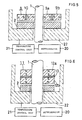
- FIG. 3 schematically shows the main portion of another superconducting bearing device, i.e., a first embodiment of the present invention.
- This bearing device comprises a rotatable member 1 in the form of a vertical shaft, and a superconductor 2.
- a permanent magnet portion 3 in the form of a horizontal disk is mounted on the rotatable member 1 concentrically therewith, and the superconductor 2 is opposed to the lower end face of the magnet portion 3 and spaced apart therefrom axially of the rotatable member 1.
- the superconductor 2 is in the form of a disk having a bore, and the rotatable member 1 extends through the bore with a clearance formed in the bore around the member 1.
- the permanent magnet portion 3 is in the form of an integral assembly and comprises a plurality of annular permanent magnets 4a, 4b, 4c arranged at a spacing radially of the member 1, and a nonmagnetic material 5 interposed therebetween.
- the portion 3 is secured to the rotatable member 1.
- the upper and lower ends of each of the magnets 4a, 4b, 4c are magnetized to polarities opposite to each other, and all the magnets 4a, 4b, 4c are magnetized to the same polarity at their same ends.
- the upper ends of all the magnets 4a, 4b, 4c are magnetized as N poles, and the lower ends thereof as S poles.
- the magnetic flux distribution around the axis of rotation is free of changes despite the rotation of the member 1.
- the superconductor 2 has the same properties as the one included in the first device and is disposed at a position spaced apart from the magnet portion 3 by a distance permitting a predetermined quantity of magnetic flux of the portion 3 to penetrate thereinto and which will not permit the rotation of the member 1 to alter the distribution of penetrating magnetic flux.
- a cooling case 22 which is cooled by a refrigerator 20 or the like via a temperature control unit 21 is fixedly provided within a housing (not shown) for the bearing device.
- the superconductor 2 is fixed to the cooling case 22.
- the superconductor 2 When the superconducting bearing device is operated, the superconductor 2 is cooled with a suitable refrigerant circulated through the cooling case 22 and maintained in a superconducting state. As in the case of the first device, the restraining action of the magnetic flux penetrating into the superconductor 2 from the permanent magnet portion 3 and trapped in the superconduct 2 holds the rotatable member 1 and the superconductor 2 opposed to each other with a predetermined spacing provided therebetween and supports the member 1 as levitated above the superconductor 2.
- the magnetism of one of the permanent magnets 4a, 4b, 4c repels that of another magnet of the same polarity, with the result that the magnetic flux extends to a greater extent axially of the rotatable member 1 than in the case where the permanent magnet portion has a single permanent magnet. Consequently, an increased quantity of flux penetrates into the superconductor 2 which is disposed as opposed to the lower end face of the magnet portion 3 for the superconductor 2 to trap the increased quantity of flux. This gives the device a greater load capacity and higher rigidity.
- second superconductors 6 may be provided as indicated in broken lines in FIG. 3. These second superconductors 6 are arranged radially outwardly of the periphery of the permanent magnet portion 3 at a distance from and as opposed to the periphery. These superconductors 6 also support the rotatable member 1, consequently giving further enhanced rigidity to the entire bearing device. These superconductors 6 may form a completely annular block or may be segments of an annular block.
- FIG. 4 schematically shows the main portion of another superconducting bearing device, i.e. a second embodiment.
- superconductors 2, 6, 7 are provided as opposed respectively to the lower end face, outer peripheral surface and upper end face of a permanent magnet portion 3 on a rotatable member 1.
- FIG. 5 schematically shows the main portion of another superconducting bearing device, i.e., a third embodiment.
- This embodiment has a permanent magnet portion 8 which also comprises a plurality of annular permanent magnets 9a, 9b arranged at a spacing radially of the rotatable member 1 and a nonmagnetic material 10 interposed therebetween.
- the side portions of each permanent magnet 9a or 9b which are opposite radially of the rotatable member 1 are magnetized to polarities opposite to each other, and the opposed side portions of the adjacent magnets 9a, 9b are magnetized to the same polarity.
- the inner side portion of the inner magnet 9a has N pole, the outer side portion thereof S pole, the inner side portion of the outer magnet 9b S pole, and the outer side portion thereof N pole.
- Three or more permanent magnets, when used, are also magnetized similarly.
- the magnetism of one side portion repels that of the other side portion having the same polarity, with the result that the magnetic flux expands both axially and radially of the rotatable member. This permits an increased quantity of flux to penetrate into the superconductor 2 which is opposed to the lower end face of the permanent magnet portion 8.
- additional superconductors may also be provided as opposed to the outer peripheral surface and the upper end face of the magnet portion 8.
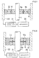
- FIG. 6 schematically shows the main portion of another superconducting bearing device, i.e., a fourth embodiment.
- This embodiment has a permanent magnet portion 11 in the form of an integral assembly and comprising a plurality of annular permanent magnets 12a, 12b arranged at a spacing axially of the rotatable member 1 and a nonmagnetic material 13 interposed therebetween.
- the side portions of each magnet 12a or 12b which are opposite axially of the rotatable member are magnetized to polarities opposite to each other, and the opposed ends of the adjacent magnets 12a, 12b are magnetized to the same polarity.
- the upper end of the upper magnet 12a is magnetized as N pole, the lower end thereof as S pole, the upper end of the lower magnet 12b as S pole, and the lower end thereof as N pole.
- the same is true of the case wherein three or more permanent magnets are used.
- the magnetism of one end repels that of the other end having the same polarity, with the result that the magnetic flux expands both axially and radially of the rotatable member. This permits an increased quantity of flux to penetrate into the superconductor 2 which is opposed to the lower end face of the magnet portion 11.
- additional superconductors may also be provided as opposed to the outer peripheral surface and the upper end face of the permanent magnet portion 11.
- FIG. 7 schematically shows the main portion of another superconducting bearing device, i.e., a fifth embodiment.
- the superconductor 2 of the third embodiment is replaced by a superconductor 6 opposed to the outer peripheral surface of the permanent magnet portion 8.
- the magnetic flux expands both axially and radially of the rotatable member also in this case, with the result that an increased quantity of flux penetrates into the superconductor 6 which is disposed as opposed to the outer peripheral surface of the magnet portion 8.
- FIG. 8 schematically shows the main portion of another superconducting bearing device, i.e., an eighth embodiment.
- the superconductor 2 of the sixth embodiment is replaced by a superconductor 6 opposed to the outer peripheral surface of the permanent magnet portion 11.
- the magnetic flux expands both axially and radially of the rotatable member also in this case, with the result that in increased quantity of flux penetrates into the superconductor 6 which is disposed as opposed to the outer peripheral surface of the magnet portion 11.
Landscapes
- Engineering & Computer Science (AREA)
- General Engineering & Computer Science (AREA)
- Mechanical Engineering (AREA)
- Magnetic Bearings And Hydrostatic Bearings (AREA)
Claims (9)
- Dispositif formant palier supraconducteur, comprenant :caractérisé en ce que ladite partie formant aimant permanent (3, 8, 11) comprend au moins deux aimants permanents annulaires (9a, 9b ; 12a, 12b) magnétisés pour avoir la même polarité au niveau de leurs extrémités adjacentes, et un matériau non magnétique (15 ; 13) intercalé entre ceux-ci.un arbre rotatif (1) ;une partie formant aimant permanent annulaire (3, 8, 11) disposée autour dudit arbre rotatif (1) de manière solidaire et concentrique avec ce dernier, ledit arbre rotatif (1) ne modifiant pas la répartition autour de son axe de rotation d'un flux magnétique généré par ladite partie formant aimant permanent annulaire (3, 8, 11) ;un carter de refroidissement (22) disposé à l'intérieur d'une enveloppe du dispositif formant palier et créant un environnement de température permettant de réaliser un état de supraconduction de type II ; etun supraconducteur de type II (2, 6, 7) pénétré par ledit arbre rotatif (1) et fixé audit carter de refroidissement (22) ;dans lequel ledit supraconducteur de type II (2, 6, 7)permet une pénétration du flux magnétique de ladite partie formant aimant permanent (3, 8, 11) ;est positionné de façon à être espacé de ladite partie formant aimant permanent (3, 8, 11) d'une distance permettant à une quantité prédéterminée du flux magnétique de ladite partie formant aimant permanent (3, 8, 11) de le pénétrer, etest positionné pour ne pas permettre une rotation dudit arbre rotatif (1) afin de modifier la répartition du flux magnétique pénétrant,
- Dispositif formant palier supraconducteur, comprenant :caractérisé en ce que ladite partie formant aimant permanent (3, 8, 11) comprend au moins deux aimants permanents annulaires (4a, 4b, 4c) magnétisés pour avoir des polarités opposées au niveau de leurs deux extrémités axiales et la même polarité au niveau de leurs extrémités axiales adjacentes, et disposés suivant des espacements différents dans la direction radiale de l'arbre rotatif (1), et un matériau non magnétique (15 ; 13) intercalé entre ceux-ci.un arbre rotatif (1) ;une partie formant aimant permanent annulaire (3, 8, 11) disposée autour dudit arbre rotatif (1) de manière solidaire et concentrique avec ce dernier, ledit arbre rotatif (1) ne modifiant pas la répartition autour de son axe de rotation d'un flux magnétique généré par ladite partie formant aimant permanent annulaire (3, 8, 11) ;un carter de refroidissement (22) disposé à l'intérieur d'une enveloppe du dispositif formant palier et créant un environnement de température permettant de réaliser un état de supraconduction de type II ; etun supraconducteur de type II (2, 6, 7) pénétré par ledit arbre rotatif (1) et fixé audit carter de refroidissement (22) ;dans lequel ledit supraconducteur de type II (2, 6, 7)permet une pénétration du flux magnétique de ladite partie formant aimant permanent (3, 8, 11) ;est positionné de façon à être espacé de ladite partie formant aimant permanent (3, 8, 11) d'une distance permettant à une quantité prédéterminée du flux magnétique de ladite partie formant aimant permanent (3, 8, 11) de le pénétrer, etest positionné pour ne pas permettre une rotation dudit arbre rotatif (1) afin de modifier la répartition du flux magnétique pénétrant,
- Dispositif formant palier supraconducteur selon la revendication 1, caractérisé en ce que lesdits aimants permanents annulaires (12a, 12b) de ladite partie formant aimant permanent (3, 11) ont des pôles magnétiques magnétisés pour avoir des polarités opposées au niveau de leurs deux extrémités axiales et sont disposés suivant un certain espacement dans la direction axiale le long de l'arbre rotatif.
- Dispositif formant palier supraconducteur selon la revendication 1, caractérisé en ce que lesdits aimants permanents annulaires (9a, 9b) de ladite partie formant aimant permanent (8) ont des pôles magnétiques magnétisés pour avoir des polarités opposées au niveau de leurs côtés radialement internes et externes et sont disposés suivant un certain espacement dans la direction radiale de l'arbre rotatif.
- Dispositif formant palier supraconducteur selon l'une quelconque des revendications 1 à 4, caractérisé en ce que ledit supraconducteur de type II (2, 7) est positionné en regard d'une surface d'extrémité axiale de ladite partie formant aimant permanent annulaire (3, 8, 11).
- Dispositif formant palier supraconducteur selon l'une quelconque des revendications 1 à 5, caractérisé en ce que ledit supraconducteur de type II (6) est positionné en regard de ladite périphérie radialement extérieure de ladite partie formant aimant permanent annulaire (3, 8, 11).
- Dispositif formant palier supraconducteur selon l'une quelconque des revendications 1 à 6, caractérisé en ce que ledit supraconducteur (2, 6, 7) est un supraconducteur céramique formé d'oxyde de type yttrium.
- Dispositif formant palier supraconducteur selon la revendication 7, caractérisé en ce que ledit supraconducteur céramique formé d'oxyde de type yttrium a des particules normalement conductrices, uniformément réparties sous la forme de points d'ancrage du flux magnétique pénétrant en lui.
- Dispositif formant palier supraconducteur selon la revendication 7 ou 8, caractérisé en ce que ledit supraconducteur céramique formé d'oxyde de type yttrium est constitué de YBa2Cu3Ox.
Priority Applications (1)
| Application Number | Priority Date | Filing Date | Title |
|---|---|---|---|
| EP98118588A EP0887569A3 (fr) | 1990-07-17 | 1991-07-17 | Méthode pour la mise en place d'un dispositif de palier supraconducteur |
Applications Claiming Priority (6)
| Application Number | Priority Date | Filing Date | Title |
|---|---|---|---|
| JP188693/90 | 1990-07-17 | ||
| JP18869390 | 1990-07-17 | ||
| JP18869390A JPH0478316A (ja) | 1990-07-17 | 1990-07-17 | 超伝導軸受 |
| JP403263/90 | 1990-12-18 | ||
| JP40326390A JP3177847B2 (ja) | 1990-12-18 | 1990-12-18 | 超電導軸受装置 |
| JP40326390 | 1990-12-18 |
Related Child Applications (2)
| Application Number | Title | Priority Date | Filing Date |
|---|---|---|---|
| EP98118588A Division EP0887569A3 (fr) | 1990-07-17 | 1991-07-17 | Méthode pour la mise en place d'un dispositif de palier supraconducteur |
| EP98118588.7 Division-Into | 1998-10-01 |
Publications (2)
| Publication Number | Publication Date |
|---|---|
| EP0467341A1 EP0467341A1 (fr) | 1992-01-22 |
| EP0467341B1 true EP0467341B1 (fr) | 1999-09-22 |
Family
ID=26505089
Family Applications (2)
| Application Number | Title | Priority Date | Filing Date |
|---|---|---|---|
| EP91111965A Expired - Lifetime EP0467341B1 (fr) | 1990-07-17 | 1991-07-17 | Dispositif de palier supraconducteur |
| EP98118588A Withdrawn EP0887569A3 (fr) | 1990-07-17 | 1991-07-17 | Méthode pour la mise en place d'un dispositif de palier supraconducteur |
Family Applications After (1)
| Application Number | Title | Priority Date | Filing Date |
|---|---|---|---|
| EP98118588A Withdrawn EP0887569A3 (fr) | 1990-07-17 | 1991-07-17 | Méthode pour la mise en place d'un dispositif de palier supraconducteur |
Country Status (3)
| Country | Link |
|---|---|
| US (2) | US5330967A (fr) |
| EP (2) | EP0467341B1 (fr) |
| DE (1) | DE69131639T2 (fr) |
Families Citing this family (39)
| Publication number | Priority date | Publication date | Assignee | Title |
|---|---|---|---|---|
| US5633548A (en) * | 1990-07-17 | 1997-05-27 | Koyo Seiko Co., Ltd. | Method for setting up a superconducting bearing device |
| US5330967A (en) * | 1990-07-17 | 1994-07-19 | Koyo Seiko Co., Ltd. | Superconducting bearing device stabilized by trapped flux |
| US5177387A (en) * | 1990-12-04 | 1993-01-05 | University Of Houston-University Park | High temperature superconducting magnetic bearings |
| US5739606A (en) * | 1991-03-15 | 1998-04-14 | Koyo Seiko Co., Ltd. | Superconducting bearing device |
| JPH06100225B2 (ja) * | 1991-03-15 | 1994-12-12 | 光洋精工株式会社 | 超電導軸受装置 |
| JPH0737812B2 (ja) * | 1991-03-15 | 1995-04-26 | 光洋精工株式会社 | 超電導軸受装置 |
| US5196748A (en) * | 1991-09-03 | 1993-03-23 | Allied-Signal Inc. | Laminated magnetic structure for superconducting bearings |
| US5256638A (en) * | 1991-11-14 | 1993-10-26 | United Technologies Corporation | Magnetically leviated superconducting bearing |
| EP0629789A4 (fr) * | 1992-02-14 | 1996-04-10 | Seiko Epson Corp | Palier supraconducteur. |
| JPH06200942A (ja) * | 1992-10-13 | 1994-07-19 | Cornell Res Found Inc | 超伝導ベアリングアセンブリ |
| DE4301076A1 (de) * | 1993-01-16 | 1994-07-21 | Forschungszentrum Juelich Gmbh | Magnetlagerzelle mit Rotor und Stator |
| US5540116A (en) * | 1993-03-03 | 1996-07-30 | University Of Chicago | Low-loss, high-speed, high-TC superconducting bearings |
| US5722303A (en) * | 1993-03-03 | 1998-03-03 | University Of Chicago | Mixed-mu superconducting bearings |
| US5479059A (en) * | 1993-08-23 | 1995-12-26 | United Technologies Corporation | Thin film superconductor magnetic bearings |
| US5563565A (en) * | 1993-11-23 | 1996-10-08 | University Of Chicago | Method for obtaining large levitation pressure in superconducting magnetic bearings |
| US5495221A (en) * | 1994-03-09 | 1996-02-27 | The Regents Of The University Of California | Dynamically stable magnetic suspension/bearing system |
| US5554583A (en) * | 1994-09-08 | 1996-09-10 | Hull; John R. | Permanent magnet design for high-speed superconducting bearings |
| JP3675010B2 (ja) * | 1995-02-17 | 2005-07-27 | セイコーエプソン株式会社 | 超電導軸受装置 |
| US5763971A (en) * | 1995-03-16 | 1998-06-09 | Koyo Seiko Co., Ltd. | Superconducting bearing device |
| JP2997632B2 (ja) * | 1995-04-27 | 2000-01-11 | 核燃料サイクル開発機構 | 回転体に対する電磁的回転加振装置及びそれを用いた回転体の制振装置 |
| US5747426A (en) * | 1995-06-07 | 1998-05-05 | Commonwealth Research Corporation | High performance magnetic bearing systems using high temperature superconductors |
| US6466119B1 (en) * | 1996-09-06 | 2002-10-15 | Chester Drew | Magnetic circuit |
| DE19847347C2 (de) * | 1998-10-14 | 2001-03-29 | Ldt Gmbh & Co | Magnetlager |
| US6416215B1 (en) | 1999-12-14 | 2002-07-09 | University Of Kentucky Research Foundation | Pumping or mixing system using a levitating magnetic element |
| US6758593B1 (en) | 2000-10-09 | 2004-07-06 | Levtech, Inc. | Pumping or mixing system using a levitating magnetic element, related system components, and related methods |
| DE10022061A1 (de) * | 2000-05-06 | 2001-11-08 | Leybold Vakuum Gmbh | Magnetlagerung mit Dämpfung |
| US6806604B2 (en) * | 2000-07-13 | 2004-10-19 | Kendro Laboratory Products Gmbh | Centrifuge with a magnetically stabilized rotor for centrifugal goods |
| DE10042962C1 (de) * | 2000-08-31 | 2002-05-02 | Siemens Ag | Magnetlager zur Lagerung einer drehbaren Welle unter Verwendung von Hoch-T¶c¶-Supraleitermaterial |
| US7086778B2 (en) * | 2000-10-09 | 2006-08-08 | Levtech, Inc. | System using a levitating, rotating pumping or mixing element and related methods |
| EP1548301B1 (fr) * | 2002-08-02 | 2007-10-10 | JTEKT Corporation | Palier magnetique supraconducteur |
| KR100920103B1 (ko) * | 2007-09-28 | 2009-10-01 | 한국전력공사 | 외륜형 고온초전도 저널 베어링 |
| DE102008042701A1 (de) * | 2008-10-09 | 2010-04-15 | How To Organize Gmbh | Linearmotor für optische Systeme |
| DE102009049889A1 (de) * | 2009-10-20 | 2011-04-21 | Schaeffler Technologies Gmbh & Co. Kg | Supraleitendes Lager und Verfahren zu dessen Montage |
| CN102518665B (zh) * | 2011-12-24 | 2014-05-07 | 李泽 | 一种磁悬浮轴承 |
| WO2016000731A1 (fr) * | 2014-07-02 | 2016-01-07 | Festo Ag & Co. Kg | Système de transport avec rouleaux à palier magnétique supraconducteur |
| DE202016003798U1 (de) | 2016-06-09 | 2016-07-20 | Jürgen Klasch | Magnetisches Ringlager |
| US20210376691A1 (en) * | 2020-06-02 | 2021-12-02 | Christopher Hugh Powell | Remote Structural Reinforcement of the Flywheel Energy Storage System |
| CN110450052B (zh) * | 2019-08-09 | 2021-04-30 | 安徽理工大学 | 一种打磨机器人主轴浮动机构 |
| RS65456B1 (sr) * | 2021-05-15 | 2024-05-31 | Sanko Tekstil Isletmeleri San Tic A S | Uređaj i postupak za predenje i upredanje vlaknastog materijala u okvire za prstenasto predenje ili prstenasto upredanje |
Family Cites Families (16)
| Publication number | Priority date | Publication date | Assignee | Title |
|---|---|---|---|---|
| US2536824A (en) * | 1949-11-19 | 1951-01-02 | Gen Electric | Laminated magnetic suspension |
| US4072370A (en) * | 1976-08-24 | 1978-02-07 | Spectra-Flux, Inc. | Radial magnetic bearing |
| JPS63243523A (ja) | 1987-03-28 | 1988-10-11 | Sumitomo Electric Ind Ltd | 超電導軸受 |
| US4797386A (en) * | 1987-04-22 | 1989-01-10 | American Telephone And Telegraph Company, At&T Bell Labs | Superconductor-magnet induced separation |
| DE3744143A1 (de) * | 1987-12-24 | 1989-07-13 | Kernforschungsanlage Juelich | Magnetische lagerung eines rotors an einem stator |
| US4987674A (en) * | 1988-07-07 | 1991-01-29 | Allied-Signal Inc. | Method of making a dynamoelectric machine with superconducting magnet rotor |
| US4886778A (en) * | 1988-08-01 | 1989-12-12 | Cornell Research Foundation Inc. | Superconducting rotating assembly |
| US5126317A (en) * | 1988-09-30 | 1992-06-30 | Eastman Kodak Company | Bearing system employing a superconductor element |
| US4892863A (en) * | 1988-09-30 | 1990-01-09 | Eastman Kodak Company | Electric machinery employing a superconductor element |
| US5120706A (en) * | 1989-03-17 | 1992-06-09 | University Of Arkansas | Drive system employing frictionless bearings including superconducting matter |
| JP2992578B2 (ja) * | 1990-07-08 | 1999-12-20 | 小山 央二 | エネルギー貯蔵装置 |
| US5330967A (en) * | 1990-07-17 | 1994-07-19 | Koyo Seiko Co., Ltd. | Superconducting bearing device stabilized by trapped flux |
| JP2893291B2 (ja) * | 1990-09-03 | 1999-05-17 | 光洋精工株式会社 | 制動装置 |
| US5126611A (en) * | 1991-02-06 | 1992-06-30 | Allied-Signal Inc. | Composite superconductor disc bearing |
| US5220232A (en) * | 1991-09-03 | 1993-06-15 | Allied Signal Aerospace | Stacked magnet superconducting bearing |
| US5196748A (en) * | 1991-09-03 | 1993-03-23 | Allied-Signal Inc. | Laminated magnetic structure for superconducting bearings |
-
1991
- 1991-07-16 US US07/730,164 patent/US5330967A/en not_active Expired - Lifetime
- 1991-07-17 DE DE69131639T patent/DE69131639T2/de not_active Expired - Fee Related
- 1991-07-17 EP EP91111965A patent/EP0467341B1/fr not_active Expired - Lifetime
- 1991-07-17 EP EP98118588A patent/EP0887569A3/fr not_active Withdrawn
-
1993
- 1993-12-03 US US08/160,796 patent/US5438038A/en not_active Expired - Lifetime
Also Published As
| Publication number | Publication date |
|---|---|
| EP0887569A2 (fr) | 1998-12-30 |
| DE69131639T2 (de) | 2000-05-04 |
| DE69131639D1 (de) | 1999-10-28 |
| EP0887569A3 (fr) | 1999-02-03 |
| US5330967A (en) | 1994-07-19 |
| EP0467341A1 (fr) | 1992-01-22 |
| US5438038A (en) | 1995-08-01 |
Similar Documents
| Publication | Publication Date | Title |
|---|---|---|
| US5438038A (en) | Superconducting bearing device stabilized by trapped flux | |
| US5177387A (en) | High temperature superconducting magnetic bearings | |
| US4886778A (en) | Superconducting rotating assembly | |
| US5196748A (en) | Laminated magnetic structure for superconducting bearings | |
| US4939120A (en) | Superconducting rotating assembly | |
| US5220232A (en) | Stacked magnet superconducting bearing | |
| US5710469A (en) | Magnetic bearing element for a rotor shaft using high-TC superconducting materials | |
| US6806604B2 (en) | Centrifuge with a magnetically stabilized rotor for centrifugal goods | |
| US5256638A (en) | Magnetically leviated superconducting bearing | |
| US6175175B1 (en) | Levitation pressure and friction losses in superconducting bearings | |
| US20030042812A1 (en) | Passive magnetic bearing for a horizontal shaft | |
| EP0575618B1 (fr) | Palier supraconducteur | |
| US5457086A (en) | Superconducting composite for magnetic bearings | |
| JPH06323334A (ja) | 超電導軸受装置 | |
| US5117139A (en) | Superconducting bearings with levitation control configurations | |
| US5633548A (en) | Method for setting up a superconducting bearing device | |
| Ma et al. | Hybrid high Tc superconducting magnetic bearings for flywheel energy storage system | |
| JP3177847B2 (ja) | 超電導軸受装置 | |
| JP3616856B2 (ja) | 軸受装置 | |
| JP3151492B2 (ja) | スライド装置 | |
| JP3232463B2 (ja) | 超電導軸受装置 | |
| JPH05172145A (ja) | 超電導磁気軸受装置 | |
| JP3174876B2 (ja) | 超電導軸受装置 | |
| JP3174877B2 (ja) | 超電導軸受装置 | |
| JPH08296647A (ja) | 軸受装置 |
Legal Events
| Date | Code | Title | Description |
|---|---|---|---|
| PUAI | Public reference made under article 153(3) epc to a published international application that has entered the european phase |
Free format text: ORIGINAL CODE: 0009012 |
|
| AK | Designated contracting states |
Kind code of ref document: A1 Designated state(s): DE FR GB |
|
| 17P | Request for examination filed |
Effective date: 19920610 |
|
| 17Q | First examination report despatched |
Effective date: 19940426 |
|
| GRAG | Despatch of communication of intention to grant |
Free format text: ORIGINAL CODE: EPIDOS AGRA |
|
| GRAG | Despatch of communication of intention to grant |
Free format text: ORIGINAL CODE: EPIDOS AGRA |
|
| GRAH | Despatch of communication of intention to grant a patent |
Free format text: ORIGINAL CODE: EPIDOS IGRA |
|
| GRAH | Despatch of communication of intention to grant a patent |
Free format text: ORIGINAL CODE: EPIDOS IGRA |
|
| GRAA | (expected) grant |
Free format text: ORIGINAL CODE: 0009210 |
|
| AK | Designated contracting states |
Kind code of ref document: B1 Designated state(s): DE FR GB |
|
| REF | Corresponds to: |
Ref document number: 69131639 Country of ref document: DE Date of ref document: 19991028 |
|
| ET | Fr: translation filed | ||
| PLBE | No opposition filed within time limit |
Free format text: ORIGINAL CODE: 0009261 |
|
| STAA | Information on the status of an ep patent application or granted ep patent |
Free format text: STATUS: NO OPPOSITION FILED WITHIN TIME LIMIT |
|
| 26N | No opposition filed | ||
| REG | Reference to a national code |
Ref country code: GB Ref legal event code: IF02 |
|
| PGFP | Annual fee paid to national office [announced via postgrant information from national office to epo] |
Ref country code: GB Payment date: 20070711 Year of fee payment: 17 |
|
| PGFP | Annual fee paid to national office [announced via postgrant information from national office to epo] |
Ref country code: DE Payment date: 20080724 Year of fee payment: 18 |
|
| PGFP | Annual fee paid to national office [announced via postgrant information from national office to epo] |
Ref country code: FR Payment date: 20080718 Year of fee payment: 18 |
|
| GBPC | Gb: european patent ceased through non-payment of renewal fee |
Effective date: 20080717 |
|
| PG25 | Lapsed in a contracting state [announced via postgrant information from national office to epo] |
Ref country code: GB Free format text: LAPSE BECAUSE OF NON-PAYMENT OF DUE FEES Effective date: 20080717 |
|
| REG | Reference to a national code |
Ref country code: FR Ref legal event code: ST Effective date: 20100331 |
|
| PG25 | Lapsed in a contracting state [announced via postgrant information from national office to epo] |
Ref country code: FR Free format text: LAPSE BECAUSE OF NON-PAYMENT OF DUE FEES Effective date: 20090731 |
|
| PG25 | Lapsed in a contracting state [announced via postgrant information from national office to epo] |
Ref country code: DE Free format text: LAPSE BECAUSE OF NON-PAYMENT OF DUE FEES Effective date: 20100202 |