EP0467342A1 - Compresseur à spirales - Google Patents
Compresseur à spirales Download PDFInfo
- Publication number
- EP0467342A1 EP0467342A1 EP91111968A EP91111968A EP0467342A1 EP 0467342 A1 EP0467342 A1 EP 0467342A1 EP 91111968 A EP91111968 A EP 91111968A EP 91111968 A EP91111968 A EP 91111968A EP 0467342 A1 EP0467342 A1 EP 0467342A1
- Authority
- EP
- European Patent Office
- Prior art keywords
- counterweight
- scroll member
- housing
- coolant gas
- intake port
- Prior art date
- Legal status (The legal status is an assumption and is not a legal conclusion. Google has not performed a legal analysis and makes no representation as to the accuracy of the status listed.)
- Granted
Links
- 239000002826 coolant Substances 0.000 claims abstract description 35
- 230000006835 compression Effects 0.000 claims abstract description 31
- 238000007906 compression Methods 0.000 claims abstract description 31
- 230000007246 mechanism Effects 0.000 claims abstract description 28
- 239000000314 lubricant Substances 0.000 claims description 5
- 238000005461 lubrication Methods 0.000 abstract description 14
- 238000007789 sealing Methods 0.000 abstract description 9
- 238000005057 refrigeration Methods 0.000 abstract description 6
- 238000011038 discontinuous diafiltration by volume reduction Methods 0.000 abstract description 2
- 238000007599 discharging Methods 0.000 description 2
- 239000012530 fluid Substances 0.000 description 2
- 230000009471 action Effects 0.000 description 1
- 230000006872 improvement Effects 0.000 description 1
- 239000002245 particle Substances 0.000 description 1
Images



Classifications
-
- F—MECHANICAL ENGINEERING; LIGHTING; HEATING; WEAPONS; BLASTING
- F04—POSITIVE - DISPLACEMENT MACHINES FOR LIQUIDS; PUMPS FOR LIQUIDS OR ELASTIC FLUIDS
- F04C—ROTARY-PISTON, OR OSCILLATING-PISTON, POSITIVE-DISPLACEMENT MACHINES FOR LIQUIDS; ROTARY-PISTON, OR OSCILLATING-PISTON, POSITIVE-DISPLACEMENT PUMPS
- F04C18/00—Rotary-piston pumps specially adapted for elastic fluids
- F04C18/02—Rotary-piston pumps specially adapted for elastic fluids of arcuate-engagement type, i.e. with circular translatory movement of co-operating members, each member having the same number of teeth or tooth-equivalents
-
- F—MECHANICAL ENGINEERING; LIGHTING; HEATING; WEAPONS; BLASTING
- F04—POSITIVE - DISPLACEMENT MACHINES FOR LIQUIDS; PUMPS FOR LIQUIDS OR ELASTIC FLUIDS
- F04C—ROTARY-PISTON, OR OSCILLATING-PISTON, POSITIVE-DISPLACEMENT MACHINES FOR LIQUIDS; ROTARY-PISTON, OR OSCILLATING-PISTON, POSITIVE-DISPLACEMENT PUMPS
- F04C29/00—Component parts, details or accessories of pumps or pumping installations, not provided for in groups F04C18/00 - F04C28/00
- F04C29/12—Arrangements for admission or discharge of the working fluid, e.g. constructional features of the inlet or outlet
-
- F—MECHANICAL ENGINEERING; LIGHTING; HEATING; WEAPONS; BLASTING
- F04—POSITIVE - DISPLACEMENT MACHINES FOR LIQUIDS; PUMPS FOR LIQUIDS OR ELASTIC FLUIDS
- F04C—ROTARY-PISTON, OR OSCILLATING-PISTON, POSITIVE-DISPLACEMENT MACHINES FOR LIQUIDS; ROTARY-PISTON, OR OSCILLATING-PISTON, POSITIVE-DISPLACEMENT PUMPS
- F04C18/00—Rotary-piston pumps specially adapted for elastic fluids
- F04C18/02—Rotary-piston pumps specially adapted for elastic fluids of arcuate-engagement type, i.e. with circular translatory movement of co-operating members, each member having the same number of teeth or tooth-equivalents
- F04C18/0207—Rotary-piston pumps specially adapted for elastic fluids of arcuate-engagement type, i.e. with circular translatory movement of co-operating members, each member having the same number of teeth or tooth-equivalents both members having co-operating elements in spiral form
- F04C18/0215—Rotary-piston pumps specially adapted for elastic fluids of arcuate-engagement type, i.e. with circular translatory movement of co-operating members, each member having the same number of teeth or tooth-equivalents both members having co-operating elements in spiral form where only one member is moving
-
- F—MECHANICAL ENGINEERING; LIGHTING; HEATING; WEAPONS; BLASTING
- F04—POSITIVE - DISPLACEMENT MACHINES FOR LIQUIDS; PUMPS FOR LIQUIDS OR ELASTIC FLUIDS
- F04C—ROTARY-PISTON, OR OSCILLATING-PISTON, POSITIVE-DISPLACEMENT MACHINES FOR LIQUIDS; ROTARY-PISTON, OR OSCILLATING-PISTON, POSITIVE-DISPLACEMENT PUMPS
- F04C2250/00—Geometry
- F04C2250/10—Geometry of the inlet or outlet
- F04C2250/101—Geometry of the inlet or outlet of the inlet
-
- F—MECHANICAL ENGINEERING; LIGHTING; HEATING; WEAPONS; BLASTING
- F05—INDEXING SCHEMES RELATING TO ENGINES OR PUMPS IN VARIOUS SUBCLASSES OF CLASSES F01-F04
- F05B—INDEXING SCHEME RELATING TO WIND, SPRING, WEIGHT, INERTIA OR LIKE MOTORS, TO MACHINES OR ENGINES FOR LIQUIDS COVERED BY SUBCLASSES F03B, F03D AND F03G
- F05B2250/00—Geometry
- F05B2250/50—Inlet or outlet
- F05B2250/501—Inlet
Definitions
- the present invention relates to a scroll type compressor suitable for an automobile air conditioner, more particularly, to an improvement thereof of the lubrication for a sealing means, bearings, and an anti-spin mechanism.
- a small size scroll type compressor suitably used for an automobile air conditioner is disclosed in Japanese Unexamined Patent Publication No. 57-62988.
- this scroll type compressor (hereinafter referred to as "compressor"), as shown in Fig. 5, a stationary scroll member 52 comprising a stationary side plate 521 and a stationary spiral body 522 is fixed to a housing half 51, and movable scroll member 54 comprising a movable side plate 541 and a movable spiral body 542 is arranged in the housing half 51 and other housing half 53.
- the movable scroll member 54 is engaged with the fixed scroll member 52, and thus a plurality of compression chambers 56 are formed therebetween.
- a driving shaft 59 Within the interior of a housing consisting of both housing halves 51 and 53, is rotatably secured a driving shaft 59 via a sealing means 57 and a main bearing 58, and a pin 60 is eccentrically mounted to the inner end of the driving shaft 59.
- a counterweight 61 To a base end region of the pin 60 closer to the main bearing 58 is fixed a counterweight 61, and to the other end region is fixed a drive bush 64 which supports the movable scroll member 54 by a bearing 63 so that, in association with an anti-spin mechanism, the movable scroll member is subjected only to an orbital motion and cannot spin on its own axis. Structures and functions of the counterweight and the anti-spin mechanism are described in detail such as in Japanese Unexamined Patent Publication Nos. 57-148,087 or 57-148,092.
- spiral bodies 522 and 542 are defined by involute curves engageable with each other, volume variations occur in each compression chamber 56 formed between the scroll members 52 and 54 in accordance with the orbital motion of the movable scroll member 54, and this causes a coolant gas to flow into the compression chamber 56 through an intake port 55, which gas is successively compressed in the chamber 56 and flows out of an exit port 65 arranged centrally in the scroll members 52, 54, into a flow-out chamber 66, and finally, is fed to a refrigeration circuit (not shown) through a fluid discharge port 67.
- the lubrication for front side mechanisms such as the sealing means 57, the bearings 58, 63 or the anti-spin mechanism 62, is carried out by oil particles contained in the coolant gas.
- the intake port 55 is provided in the housing wall closer to a rear side, i.e., to the compression chamber 56, rather than to the lubrication indispensable mechanisms in the front side area, so that the coolant gas can be directly taken into the compression chamber 56 while keeping the intake resistance at a lowest level. Accordingly, the coolant gas cannot be smoothly introduced to the lubrication indispensable mechanism, whereby it also becomes difficult to be sufficiently feed the lubricant in the coolant gas to such mechanisms, and in the worst case, a seizure or over-wear of these mechanisms may occur.
- an object of the present invention is to provide a means for readily feeding a sufficient amount of lubricant to the mechanisms arranged in the front side region of the scroll type compressor, while avoiding an increase of the intake resistance of the coolant gas.
- a scroll type compressor comprising a housing, a stationary scroll member fixed to the housing, a movable scroll member engaged with the stationary scroll member and forming compression chambers between the two scroll members, a drive shaft rotatably secured in the housing by a main bearing, a pin eccentrically mounted on the inner end region of the pin, a drive bush secured on the pin and supporting the movable scroll member so that the movable scroll member is subjected to an orbital motion via a bearing while inhibited, by an association with an anti-spin mechanism, from a rotation about its own axis, and a counterweight mounted on the drive shaft for absorbing a dynamic unbalance of the movable scroll member, whereby a coolant gas it taken into the compression chamber through an intake port and pressurized in the compression chamber before being discharged therefrom, in accordance with the orbital motion of the movable scroll member, and is characterized in that the intake port is formed in a region of the housing wall where the extention of
- the counterweight is shaped to positively guide the coolant gas toward the front side area.
- the surface of the counterweight closer to the front side area may be tapered so that the counterweight has a thinner width from the center of rotation toward the periphery thereof.
- the coolant gas is sucked into the interior of the housing through the intake port formed in the defined region of the housing wall, due to a negative pressure caused by the rotation of the counterweight.
- the coolant gas flows into the housing without the interference of the counterweight and penetrates the lubrication indispensable mechanisms in the front side area, such as the sealing means, the main bearing or the anti-spin mechanism, whereby the sufficient lubrication can be performed. Thereafter, the coolant gas is introduced into the compression chamber.
- a scroll type compressor of a first embodiment of the present invention has a stationary scroll member 2 consisting of a stationary side plate 21, an outer shell 22 formed integrally with the stationary side plate 21, and a stationary spiral body 23 formed in the inner side of the stationary side plate 21 and defined by an involute curve.
- the stationary scroll member 2 is associated with a movable scroll member 4 consisting of a movable side plate 41 and a movable spiral body 42 formed in the inner side of the stationary side plate 41, and is defined by another involute curve so that a plurality of compression chambers 39 are formed by the engagement of the spiral bodies 23, 42 with each other.
- a drive shaft 33 is rotatably supported by a sealing means 31 and a main bearing 32.
- a pin 34 At the inner end of a larger diameter portion of the drive shaft 33 is eccentrically implanted a pin 34 to which a drive bush 36 is mounted.
- the bush 36 rotatably supports the movable scroll member 4 through a bearing 38 so that the movable scroll member can be subjected to an orbital motion while preventing a rotation thereof about its own axis, in association with an anti-spin mechanism 37.
- a counterweight 35 is secured to the pin 34 or the drive bush 36 for absorbing a dynamic unbalance of the movable scroll member 4.
- the anti-spin mechanism 37 consists of a stationary race 371 fixedly secured to the front housing 30, a stationary ring 372 fixedly mounted to the race 371 and having a plurality of positioning apertures 372a circularly arranged at a distance therebetween, a plurality of balls 373, each accommodated in the respective aperture 372a, and a movable ring 374 arranged opposite to the stationary ring 372 and having a plurality of positioning apertures 374a coinciding with the respective balls 373.
- the movable side plate 41 of the movable scroll member 4 is fixedly secured to the movable ring 374 of the anti-spin mechanism 37, and an exit port 11 is provided through the central portion of the stationary side plate 21 of the stationary scroll member 2 and communicated with the compression chamber 39 in the discharging phase.
- a rear housing 10 is fixedly secured to the stationary scroll member 2 to form a flow-out chamber 13 inside of the rear housing 10, and the flow-out chamber 13 is communicated with the compression chamber 39 through the exit port 11 via a check valve 12, and with a refrigeration circuit through a fluid discharging port (not shown).
- a characteristic feature of the present invention is the structure of an intake port 8 communicating with the refrigeration circuit.
- the intake port 8 is formed in the wall of the front housing 30 so that it is positioned in a region with which an extension of a rotational plane of the counterweight 35 intersects. That is, during the rotation of the counterweight, the periphery 35a of the counterweight can alternately occupy two positions, away from the intake port 8 and closer thereto.
- An intake path 9 is formed through the wall of the front housing 30, the stationary race 371 and the stationary ring 372 so that the intake port 8 is directly communicated with the interior of the compression chamber 39, whereby a coolant gas can flow into the compression chamber 39 without interference by the counterweight 35.
- the coolant gas is sufficiently fed to the lubricant indispensable mechanisms once a rotation of the counterweight.
- the structure of the inventive compressor is relatively simple and can be easily and effectively manufactured. Also, as the intake resistance of the coolant gas is not increased compared to the conventional compressor, the engine is not subjected to an excessive burden.
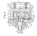
- FIG. 4 A second embodiment of the present invention will be explained below with reference to Fig. 4.
- the basic structure thereof is substantially the same as that of the first embodiment, and accordingly, the same reference numerals are used in Fig. 4 as used in Figs. 1 through 3 to designate similar parts and clarify the relationship therebetween.
- the shape of a counterweight 351 is different from that shown in Fig. 1, i.e., a thickness of the counterweight 351 becomes thinner as a function of a distance from the rotational center to the periphery of the counterweight, as defined by a slanted front side surface 35b.
- a thickness of the counterweight 351 becomes thinner as a function of a distance from the rotational center to the periphery of the counterweight, as defined by a slanted front side surface 35b.
- the intake port is provided through the wall of the front housing, but this is not essential to the present invention, as the intake port may be formed in another position if the structure of the compressor permits, provided that it confronts the periphery of the counterweight. Also, the intake path need not be bored through the stationary race, if the structure of the compressor permits.
- a scroll type compressor comprising a stationary scroll member (2) and a movable scroll member (4) accommodated in a housing (10, 39), the scroll members (2, 4) being engaged with each other so that the movable scroll member (4) is subjected to an orbital motion around the stationary scroll member (2) and forms compression chambers (39) therebetween, in which chambers (39) a coolant gas is compressed by a volume reduction of the chamber (39) in accordance with the orbital motion, and is discharged therefrom to a refrigeration circuit.
- An intake port (8) for introducing the coolant gas into the housing (10, 30) is provided at a position closer to lubrication indispensable mechanisms such as a main bearing (32) or a sealing means (31) while confronting the periphery of a counterweight (35).
- the coolant gas is sucked into the interior of the housing (10, 39) and fed to the lubrication indispensable mechanisms (31, 32).
- the counterweight (35) is positioned on the side closer to the intake port (8), the coolant gas is introduced directly therefrom to the compression chamber (39).
Landscapes
- Engineering & Computer Science (AREA)
- Mechanical Engineering (AREA)
- General Engineering & Computer Science (AREA)
- Rotary Pumps (AREA)
Applications Claiming Priority (2)
| Application Number | Priority Date | Filing Date | Title |
|---|---|---|---|
| JP76435/90U | 1990-07-18 | ||
| JP1990076435U JP2552309Y2 (ja) | 1990-07-18 | 1990-07-18 | スクロール型圧縮機 |
Publications (2)
| Publication Number | Publication Date |
|---|---|
| EP0467342A1 true EP0467342A1 (fr) | 1992-01-22 |
| EP0467342B1 EP0467342B1 (fr) | 1996-01-24 |
Family
ID=13605075
Family Applications (1)
| Application Number | Title | Priority Date | Filing Date |
|---|---|---|---|
| EP91111968A Expired - Lifetime EP0467342B1 (fr) | 1990-07-18 | 1991-07-17 | Compresseur à spirales |
Country Status (4)
| Country | Link |
|---|---|
| EP (1) | EP0467342B1 (fr) |
| JP (1) | JP2552309Y2 (fr) |
| KR (1) | KR950007475B1 (fr) |
| DE (1) | DE69116616T2 (fr) |
Cited By (1)
| Publication number | Priority date | Publication date | Assignee | Title |
|---|---|---|---|---|
| EP2708750A4 (fr) * | 2011-05-13 | 2014-11-26 | Sanden Corp | Compresseur à spirales |
Families Citing this family (1)
| Publication number | Priority date | Publication date | Assignee | Title |
|---|---|---|---|---|
| WO2006068664A2 (fr) | 2004-07-13 | 2006-06-29 | Tiax Llc | Systeme et procede de refrigeration |
Citations (1)
| Publication number | Priority date | Publication date | Assignee | Title |
|---|---|---|---|---|
| US4484869A (en) * | 1981-04-24 | 1984-11-27 | Kabushiki Kaisha Toyoda Jidoshokki Seisakusho | Volumetric fluid compressor |
Family Cites Families (2)
| Publication number | Priority date | Publication date | Assignee | Title |
|---|---|---|---|---|
| JPS5924992U (ja) * | 1982-08-07 | 1984-02-16 | サンデン株式会社 | スクロ−ル型圧縮機 |
| JPS5952193U (ja) * | 1982-09-30 | 1984-04-05 | サンデン株式会社 | スクロ−ル型圧縮機 |
-
1990
- 1990-07-18 JP JP1990076435U patent/JP2552309Y2/ja not_active Expired - Lifetime
-
1991
- 1991-06-19 KR KR1019910010137A patent/KR950007475B1/ko not_active Expired - Fee Related
- 1991-07-17 DE DE69116616T patent/DE69116616T2/de not_active Expired - Fee Related
- 1991-07-17 EP EP91111968A patent/EP0467342B1/fr not_active Expired - Lifetime
Patent Citations (1)
| Publication number | Priority date | Publication date | Assignee | Title |
|---|---|---|---|---|
| US4484869A (en) * | 1981-04-24 | 1984-11-27 | Kabushiki Kaisha Toyoda Jidoshokki Seisakusho | Volumetric fluid compressor |
Non-Patent Citations (2)
| Title |
|---|
| PATENT ABSTRACTS OF JAPAN, vol. 13, no. 485 (M-887)[3833], 6th November 1989; & JP-A-1 193 091 (MITSUI SEIKI) 03-08-1989 * |
| PATENT ABSTRACTS OF JAPAN, vol. 9, no. 297 (M-432)[2020], 25th November 1985; & JP-A-60 135 684 (TOYODA JIDO SHOKKI) 19-07-1985 * |
Cited By (1)
| Publication number | Priority date | Publication date | Assignee | Title |
|---|---|---|---|---|
| EP2708750A4 (fr) * | 2011-05-13 | 2014-11-26 | Sanden Corp | Compresseur à spirales |
Also Published As
| Publication number | Publication date |
|---|---|
| DE69116616T2 (de) | 1996-06-05 |
| JPH0434486U (fr) | 1992-03-23 |
| EP0467342B1 (fr) | 1996-01-24 |
| DE69116616D1 (de) | 1996-03-07 |
| KR950007475B1 (ko) | 1995-07-11 |
| JP2552309Y2 (ja) | 1997-10-29 |
| KR920002932A (ko) | 1992-02-28 |
Similar Documents
| Publication | Publication Date | Title |
|---|---|---|
| EP0665921B1 (fr) | Appareil a helices a chute de pression reduite a l'entree | |
| US6276910B1 (en) | Scroll-type compressor having an oil groove intersecting the suction port | |
| US4314796A (en) | Scroll-type compressor with thrust bearing lubricating and bypass means | |
| EP0903499B1 (fr) | Compresseur à spirales | |
| US11624364B2 (en) | Electric compressor | |
| US4470778A (en) | Scroll type fluid displacement apparatus with oil separating mechanism | |
| US8152503B2 (en) | Baffle member for scroll compressors | |
| EP2218914A2 (fr) | Machine à spirales | |
| EP1122437A2 (fr) | Compresseur à spirales | |
| US11473580B2 (en) | Electric compressor | |
| EP0648932B1 (fr) | Compresseur à spirales | |
| US5221198A (en) | Scroll type compressor with intake port aligned with counterweight | |
| US5704773A (en) | Oldham coupling mechanism of a scroll type fluid displacement apparatus | |
| US6179591B1 (en) | Conical hub bearing for scroll machine | |
| US6158980A (en) | Compressor with motor | |
| EP0467342B1 (fr) | Compresseur à spirales | |
| JPH07167069A (ja) | スクロール型圧縮機 | |
| US5456584A (en) | Scroll type compressor with refrigerant gas passage in balance weight | |
| JPH09158865A (ja) | スクロール圧縮機 | |
| JPH1047283A (ja) | スクロール圧縮機 | |
| JPH07158566A (ja) | スクロール型圧縮機 | |
| EP0240739B1 (fr) | Système de lubrification pour compresseur à volutes | |
| WO2018030065A1 (fr) | Machine à fluide de type à volute | |
| JP3383602B2 (ja) | 気体圧縮機 | |
| JPH08159057A (ja) | 横置き型スクロール流体機械 |
Legal Events
| Date | Code | Title | Description |
|---|---|---|---|
| PUAI | Public reference made under article 153(3) epc to a published international application that has entered the european phase |
Free format text: ORIGINAL CODE: 0009012 |
|
| 17P | Request for examination filed |
Effective date: 19910816 |
|
| AK | Designated contracting states |
Kind code of ref document: A1 Designated state(s): DE FR GB IT |
|
| 17Q | First examination report despatched |
Effective date: 19921203 |
|
| GRAA | (expected) grant |
Free format text: ORIGINAL CODE: 0009210 |
|
| AK | Designated contracting states |
Kind code of ref document: B1 Designated state(s): DE FR GB IT |
|
| ITF | It: translation for a ep patent filed | ||
| REF | Corresponds to: |
Ref document number: 69116616 Country of ref document: DE Date of ref document: 19960307 |
|
| ET | Fr: translation filed | ||
| PLBE | No opposition filed within time limit |
Free format text: ORIGINAL CODE: 0009261 |
|
| STAA | Information on the status of an ep patent application or granted ep patent |
Free format text: STATUS: NO OPPOSITION FILED WITHIN TIME LIMIT |
|
| 26N | No opposition filed | ||
| PGFP | Annual fee paid to national office [announced via postgrant information from national office to epo] |
Ref country code: GB Payment date: 19980708 Year of fee payment: 8 |
|
| PG25 | Lapsed in a contracting state [announced via postgrant information from national office to epo] |
Ref country code: GB Free format text: LAPSE BECAUSE OF NON-PAYMENT OF DUE FEES Effective date: 19990717 |
|
| GBPC | Gb: european patent ceased through non-payment of renewal fee |
Effective date: 19990717 |
|
| PGFP | Annual fee paid to national office [announced via postgrant information from national office to epo] |
Ref country code: FR Payment date: 20040708 Year of fee payment: 14 |
|
| PGFP | Annual fee paid to national office [announced via postgrant information from national office to epo] |
Ref country code: DE Payment date: 20040729 Year of fee payment: 14 |
|
| PG25 | Lapsed in a contracting state [announced via postgrant information from national office to epo] |
Ref country code: IT Free format text: LAPSE BECAUSE OF NON-PAYMENT OF DUE FEES;WARNING: LAPSES OF ITALIAN PATENTS WITH EFFECTIVE DATE BEFORE 2007 MAY HAVE OCCURRED AT ANY TIME BEFORE 2007. THE CORRECT EFFECTIVE DATE MAY BE DIFFERENT FROM THE ONE RECORDED. Effective date: 20050717 |
|
| PG25 | Lapsed in a contracting state [announced via postgrant information from national office to epo] |
Ref country code: DE Free format text: LAPSE BECAUSE OF NON-PAYMENT OF DUE FEES Effective date: 20060201 |
|
| PG25 | Lapsed in a contracting state [announced via postgrant information from national office to epo] |
Ref country code: FR Free format text: LAPSE BECAUSE OF NON-PAYMENT OF DUE FEES Effective date: 20060331 |
|
| REG | Reference to a national code |
Ref country code: FR Ref legal event code: ST Effective date: 20060331 |