EP0467343A2 - Optischer Heterodyninterferometer - Google Patents
Optischer Heterodyninterferometer Download PDFInfo
- Publication number
- EP0467343A2 EP0467343A2 EP91111969A EP91111969A EP0467343A2 EP 0467343 A2 EP0467343 A2 EP 0467343A2 EP 91111969 A EP91111969 A EP 91111969A EP 91111969 A EP91111969 A EP 91111969A EP 0467343 A2 EP0467343 A2 EP 0467343A2
- Authority
- EP
- European Patent Office
- Prior art keywords
- light
- measured
- interference
- information
- frequency
- Prior art date
- Legal status (The legal status is an assumption and is not a legal conclusion. Google has not performed a legal analysis and makes no representation as to the accuracy of the status listed.)
- Ceased
Links
- 230000003287 optical effect Effects 0.000 title claims abstract description 36
- 230000001678 irradiating effect Effects 0.000 claims abstract description 5
- 238000001514 detection method Methods 0.000 claims description 30
- 230000004075 alteration Effects 0.000 claims description 23
- 238000000034 method Methods 0.000 claims description 8
- 230000001427 coherent effect Effects 0.000 claims description 6
- 238000005286 illumination Methods 0.000 claims 5
- 230000002452 interceptive effect Effects 0.000 claims 3
- 230000010287 polarization Effects 0.000 description 17
- 238000005259 measurement Methods 0.000 description 11
- 238000010586 diagram Methods 0.000 description 7
- 230000000694 effects Effects 0.000 description 4
- 230000014509 gene expression Effects 0.000 description 4
- 238000012545 processing Methods 0.000 description 3
- 238000012937 correction Methods 0.000 description 2
- 238000006073 displacement reaction Methods 0.000 description 2
- 239000000463 material Substances 0.000 description 2
- 238000013459 approach Methods 0.000 description 1
- 239000000284 extract Substances 0.000 description 1
- 230000010355 oscillation Effects 0.000 description 1
- 230000002123 temporal effect Effects 0.000 description 1
- 239000012780 transparent material Substances 0.000 description 1
Images


Classifications
-
- G—PHYSICS
- G01—MEASURING; TESTING
- G01B—MEASURING LENGTH, THICKNESS OR SIMILAR LINEAR DIMENSIONS; MEASURING ANGLES; MEASURING AREAS; MEASURING IRREGULARITIES OF SURFACES OR CONTOURS
- G01B9/00—Measuring instruments characterised by the use of optical techniques
- G01B9/02—Interferometers
- G01B9/02055—Reduction or prevention of errors; Testing; Calibration
- G01B9/02075—Reduction or prevention of errors; Testing; Calibration of particular errors
- G01B9/02076—Caused by motion
- G01B9/02077—Caused by motion of the object
-
- G—PHYSICS
- G01—MEASURING; TESTING
- G01B—MEASURING LENGTH, THICKNESS OR SIMILAR LINEAR DIMENSIONS; MEASURING ANGLES; MEASURING AREAS; MEASURING IRREGULARITIES OF SURFACES OR CONTOURS
- G01B11/00—Measuring arrangements characterised by the use of optical techniques
- G01B11/24—Measuring arrangements characterised by the use of optical techniques for measuring contours or curvatures
- G01B11/255—Measuring arrangements characterised by the use of optical techniques for measuring contours or curvatures for measuring radius of curvature
-
- G—PHYSICS
- G01—MEASURING; TESTING
- G01B—MEASURING LENGTH, THICKNESS OR SIMILAR LINEAR DIMENSIONS; MEASURING ANGLES; MEASURING AREAS; MEASURING IRREGULARITIES OF SURFACES OR CONTOURS
- G01B9/00—Measuring instruments characterised by the use of optical techniques
- G01B9/02—Interferometers
- G01B9/02001—Interferometers characterised by controlling or generating intrinsic radiation properties
- G01B9/02002—Interferometers characterised by controlling or generating intrinsic radiation properties using two or more frequencies
-
- G—PHYSICS
- G01—MEASURING; TESTING
- G01J—MEASUREMENT OF INTENSITY, VELOCITY, SPECTRAL CONTENT, POLARISATION, PHASE OR PULSE CHARACTERISTICS OF INFRARED, VISIBLE OR ULTRAVIOLET LIGHT; COLORIMETRY; RADIATION PYROMETRY
- G01J9/00—Measuring optical phase difference; Determining degree of coherence; Measuring optical wavelength
- G01J9/04—Measuring optical phase difference; Determining degree of coherence; Measuring optical wavelength by beating two waves of a same source but of different frequency and measuring the phase shift of the lower frequency obtained
-
- G—PHYSICS
- G01—MEASURING; TESTING
- G01B—MEASURING LENGTH, THICKNESS OR SIMILAR LINEAR DIMENSIONS; MEASURING ANGLES; MEASURING AREAS; MEASURING IRREGULARITIES OF SURFACES OR CONTOURS
- G01B2290/00—Aspects of interferometers not specifically covered by any group under G01B9/02
- G01B2290/45—Multiple detectors for detecting interferometer signals
-
- G—PHYSICS
- G01—MEASURING; TESTING
- G01B—MEASURING LENGTH, THICKNESS OR SIMILAR LINEAR DIMENSIONS; MEASURING ANGLES; MEASURING AREAS; MEASURING IRREGULARITIES OF SURFACES OR CONTOURS
- G01B2290/00—Aspects of interferometers not specifically covered by any group under G01B9/02
- G01B2290/70—Using polarization in the interferometer
-
- G—PHYSICS
- G01—MEASURING; TESTING
- G01J—MEASUREMENT OF INTENSITY, VELOCITY, SPECTRAL CONTENT, POLARISATION, PHASE OR PULSE CHARACTERISTICS OF INFRARED, VISIBLE OR ULTRAVIOLET LIGHT; COLORIMETRY; RADIATION PYROMETRY
- G01J9/00—Measuring optical phase difference; Determining degree of coherence; Measuring optical wavelength
- G01J9/02—Measuring optical phase difference; Determining degree of coherence; Measuring optical wavelength by interferometric methods
- G01J2009/0207—Double frequency, e.g. Zeeman
Definitions
- This invention relates to a measuring apparatus, and more particularly, for example, to an optical heterodyne interferometer which detects the three-dimensional shape of an object to be measured by detecting optical phase changes of incident light waves in accordance with the shape of the object to be measured.
- An optical heterodyne interferometer has been known as an apparatus which can detect the shape of an optical member, such as a lens, a mirror or the like, utilizing interference of optical waves.
- an apparatus is described, for example, in Applied Optics, Vol. 19, No. 1 (1980), pp. 154 - 160.
- FIG. 1 is a schematic diagram of the principal part of an optical system of a conventinal optical heterodyne interferometer.
- a light wave emitted from a laser 1 is reflected by a mirror M1, and is divided into reflected light and transmitted light by a beam splitter 2.
- the transmitted light (the first light wave) passing a Bragg cell 5a, a mirror M2 and a X/2 plate 4, and the reflected light (the second light wave) passing a Bragg cell 5b and a mirror M3 are combined by a beam splitter 3.
- the frequency of the first light wave passing through the Bragg cell 5a is shifted by a frequency f1
- the plane of the polarization of the first light wave passing through the X/2 plate 4 is rotated by 90 degrees.
- the frequency of the second light wave passsing through the Bragg cell 5b is shifted by a frequency f2.
- the diameter of the combined light beam is expanded by a beam expander 6, and is incident upon a polarizing beam splitter 7.
- the first light wave having the frequency f1 passes through the polarizing beam splitter 7, is made to be a circularly polarized light beam by the X/2 plate 8b, and is incident upon an object 11 to be measured via a collimating lens 10.
- a wavefront to be measured reflected by the object 11 to be measured is returned to the original optical path.
- the direction of polarization (the plane of polarization) of the returned light wave after passing through the X/4 plate 8b is displaced by 90 degrees from the direction of polarization when the light wave was first incident.
- the returned light wave is reflected by the polarizing beam splitter 7.
- the second light wave having the frequency f2 is reflected by the polarizing beam splitter 7, is made to be a circularly polarized light beam by a X/4 plate 8a.
- a reference wave front reflected by a reference plane mirror 9 becomes a circularly polarized light rotating in the reverse direction, and is returned to the original optical path.
- the returned light wave passes through the X/4 plate 8a, where the light wave becomes a linearly polarized light having a direction of polarization (a plane of polarization) displaced by 90 degrees from the direction of polarization when the light wave was first incident.
- the returned light wave passes through the polarizing beam splitter 7, and is combined (synthesized) with the above-described wavefront to be measured.
- the combined two light waves i.e., the wavefront to be measured and the reference wavefront, are made to be coherent wave fronts by a polarizer 12 so as to interfere with each other.
- a light wave as a result of interference is detected as a heterodyne signal having a frequency shift difference of f1 - f2 by a photodetector 15 and an image dissector camera 16.
- the image dissector camera 16 selects an arbitrary point of a two-dimensional image by a command from a computer 18, and can detect an intensity signal of light incident upon that point in real time.
- the phase distribution of the heterodyne signal f1 - f2 in the present embodiment directly represents an error in the shape of the object 11 to be measured obtained from a spherical wave formed by the collimating lens 10, if the reference plane mirror 9 is assumed to have an deal plane.
- phase difference ⁇ between a reference signal R and a measuring signal S is detected by a phase meter 17, where the reference signal R represents a heterodyne signal obtained from the photodetector 15, and the measuring signal S represents each signal from the image dissector camera 16.
- Respective measured points by the image dissector camera 16 are two-dimensionally scanned by a command from the computer 18 to obtain the two-dimensional distribution of the phase difference ⁇ between the measuring signal S and the reference signal R at respective points of measurement.
- a time of about 0.1 second to a few seconds is needed in most cases until a surface to be measured is two-dimensionally scanned by the image dissector camera 16, and the detection of optical signals at all points is completed. Accordingly, if, for example, the object 11 to be measured, the reference plane mirror 9 or the like vibrates or tilts during measurement, a component due to tilt around a point where a reference signal is detected or an amplitude caused by vibration is detected as a measurement error, reducing accuracy in measurement.
- a scanning detection means such as an image dissector camera or the like
- the invention is directed to measuring apparatus in which light irradiates a portion of an object to be measured.
- a reference light interferes with the light from respective points of the irradiated portion and interference information of the light from the respective points is detected.
- Tilt variation information of the portion being measured is detected during the interference information detection and wavefront aberration information of the light from the portion being measured is detected according to the result of the interference information detection and the tilt variation detection.
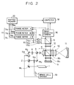
- FIG. 2 is a schematic diagram of the principal part of an optical system according to a first embodiment of the present invention.
- the apparatus of the present embodiment differs from the conventional optical heterodyne interferometer shown in FIG. 1 particularly in that a heterodyne signal reflected by the beam splitter 13 is detected by three photodetectors which are not disposed on a straight line but are disposed at respective points on a plane, and the shape of the object 11 to be measured is detected utilizing output signals from the three photodetectors.
- a light source 1 comprises a laser emitting a coherent light beam.
- a beam splitter 2 divides the light beam from the laser 1 into two, i.e., reflected and transmitted, light beams.
- Each of Bragg cells 5a and 5b provides a frequency shift for an incident light beam using a acousto-optical effect.
- a light wave subjected to the frequency shift of a frequency f1 is issued from the Bragg cell 5a
- a light wave subjected to the frequency shift of a frequency f2 is issued from the Bragg cell 5b.
- a X/2 plate 4 rotates the plane of polarization of an incident light beam by 90 degrees.
- a beam splitter 3 combines the light wave having the frequency f1 from the Bragg cell 5a and the light beam having the frequency f2 from the Bragg cell 5b.
- a beam expander 6 expands the diameter of an incident light beam and issues the expanded light beam.
- a polarizing beam splitter 7 reflects or transmits an incident light beam in accordance with the polarization state of the incident light beam to change the moving direction of the light beam.
- Each of X/4 plates 8a and 8b converts a linearly polarized light beam into a circularly polarized light beam.
- a reference plane mirror 9 forms a reference wavefront.
- a collimating lens 10 condenses an incident light beam, and projects the condensed light beam onto an object 11 to be measured.
- the object 11 to be measured comprises a mirror, a lens or the like, whose three-dimensional shape, uniformness of material, and the like are to be detected.
- the object 11 to be measured comprises a concave mirror, and the apparatus measures the shape of the surface of the concave mirror.
- a polarizer 12 extracts specific polarization components from light waves having two orthogonal linearly polarized components, and makes the extracted components interfere with each other.
- a beam splitter 13 divides an incident light beam into two, i.e., reflected and transmitted, light beams.
- a pinhole plate 14 includes a plurality of pinholes each passing only a light beam incident upon a specific position. In the present embodiment, as shown in FIG. 3(A), three pinholes 14a, 14b and 14c are provided in the x and y directions (In FIG. 2, for the convenience of explanation, the pinholes are shown aligned on a line).
- a first detection means 15 comprises three photodetectors 15a, 15b and 15c.
- the three photodetectors 15a, 15b and 15c are not disposed on a straight line (In FIG. 2, for the convenience of explanation, the detectors are shown aligned on a line), but are disposed, for example as shown in FIG. 3(B), separated with predetermined distances L x and Ly in the x and y directions, respectively.
- An image dissector camera 16 serves as a second detection means, and reads in real time an optical signal of a position whose address has been assigned by a computer 18.
- a phase detection means 17 comprises three phase meters 17a, 17b and 17c. Each of the phase meters 17a, 17b and 17c measures the phase difference between two signals input from each photodetector 15 or the image dissector camera 16.
- a buffer memory 20 temporarily stores signals relating to phase differences transmitted from the phase meters 17a, 17b and 17c.
- the computer 18 performs arithmetic processing, as will be described later, using signals from the image dissector camera 16 and measured data from the buffer memory 20.
- a light wave emitted from the laser 1 is reflected by a mirror M1, and is divided into a reflected light beam and a transmitted light beam by the beam splitter 2.
- the transmitted light beam (the first light wave) passing the Bragg cell 5a, a mirror M2 and the X/2 plate 4, and the reflected light beam (the second light wave) passing the Bragg cell 5b and a mirror M3 are combined by the beam splitter 3.
- the frequency of the first light wave passing through the Bragg cell 5a is shifted by a frequency f1
- the plane of the polarization of the first light wave passing through the X/2 plate 4 is rotated by 90 degrees.
- the frequency of the second light wave passsing through the Bragg cell 5b is shifted by a frequency f2.
- the diameter of the combined light beam is expanded by the beam expander 6, and is incident upon the polarizing beam splitter 7.
- the first light wave having the frequency f1 passes through the polarizing beam splitter 7, is made to be a circularly polarized light beam by the X/2 plate 8b, and is incident upon the object 11 to be measured via the collimating lens 10.
- a wavefront to be measured reflected by the object 11 to be measured is returned to the original optical path.
- the direction of polarization (the plane of polarization) of the returned light wave after passing through the X/4 plate 8b is displaced by 90 degrees from the direction of polarization when the light wave was first incident, since the returned light wave reflected by the object 11 to be measured has become a circularly polarized light beam rotated in the direction reverse to the direction when the light wave was first incident.
- the returned light wave is reflected by the polarizing beam splitter 7.
- the second light wave having the frequency f2 is reflected by the polarizing beam splitter 7, and is made to be a circularly polarized light beam by the X/4 plate 8a.
- a reference wave front reflected by the reference plane mirror 9 becomes a circularly polarized light rotating in the reverse direction, and is returned to the original optical path.
- the returned light wave passes through the X/4 plate 8a, where the light wave becomes a linearly polarized light having a direction of polarization (a plane of polarization) displaced by 90 degrees from the direction of polarization when the light wave was first incident.
- the returned light wave passes through the polarizing beam splitter 7, and is combined (synthesized) with the above-described wavefront to be measured.
- the combined two light waves i.e., the wavefront to be measured and the reference wavefront are made to be coherent wavefronts by a polarizer 12 so as to interfere with each other.
- a light wave as a result of interference is detected as a heterodyne signal having a frequency shift difference of f1 - f2 by the photodetectors 15a, 15b and 15c, and the image dissector camera 16.
- the phase distribution of the heterodyne signal f1 - f2 detected by the image dissector camera 16 in the present embodiment directly represents an error in the shape of the object 11 to be measured obtained from a spherical wave formed by the collimating lens 10, if it is assumed that no error components are present in other optical elements, for example, the reference plane mirror 9 has an ideal plane, and that a phase difference with a reference signal is 0 for each measured position in a state wherein no errors in shape are present in the object to be measured.
- phase difference q) between a reference signal R and a measuring signal S is detected by a phase meter 17a, where the reference signal R represents a heterodyne signal obtained, for example, from the photodetector 15a among heterodyne signals obtained from the photodetectors 15a, 15b and 15c, and the measuring signal S represents a signal corresponding to a specific point on the object to be measured from the image dissector camera 16.
- the image dissector camera 16 two-dimensionally scans respective measured points by a command from the computer 18 to obtain the two-dimensional distribution of the phase difference ⁇ a -(x,y) between the measuring signal S and the reference signal R at each measured point (x, y). A wavefront aberration due to the shape of the object 11 to be measured is thereby detected.
- the image dissector camera 16 two-dimensionally scans the surface to be measured of the object 11 to be measured, if, for example, the object 11 to be measured or the reference plane mirror 9 vibrates to provide an effect of tilt, a measurement error is produced.
- the reference signal R from the photodetector 15a and the data of phase differences ⁇ a,b and ⁇ a,c which are phase differences between signals from the two spatially separated photodetectors 15a and 15b, and between signals from the two spatially separated photodetectors 15a and 15c, as shown in FIG. 3(B), are measured simultaneously with the measurement of the phase difference ⁇ P a (x,y) or with a period which is sufficiently shorter than the period of mechanical vibration from the start to the end of the two-dimensional scanning by the image dissector camera 16, and the measured data are stored in the buffer memory 20.
- FIGS. 4(A) and 4(B) illustrate the results of measurement of the phase differences ⁇ a,b and ⁇ a,c with time as the abscissa.
- reference numerals 31 and 32 represent values (phase differences) when no mechanical vibration is present
- reference numerals 31 a and 32a represent values (phase differences) when mechanical vibration is present. These values are displaced with time.
- the computer 18 corrects the amount of vibration using information of wavefront aberration relating to the object 11 to be measured and information of the amount of vibration at that time, and obtains a correct wavefront aberration relating to the object 11 to be measured.
- the photodetectors 15a and 15c are disposed separated with a distance L x in a direction parallel to the x axis on an image pickup surface 16a of the image dissector camera 16, and the photodetectors 15a and 15b are disposed separated with a distance Ly in a direction parallel to the y axis.
- phase difference between a reference signal R obtained from the photodetector 15a, and a measuring signal S measured at an address (X,Y) on the image pickup surface 16a of the image dissector camera 16 corresponding to a point (x,y) of measurement is repesented by ⁇ P a (X,Y), and the phase differences between the reference signal R obtained from the photodetector 15a and measuring signals measured by the photodetectors 15b and 15c at the time of the measurement at the address (X,Y) are represented by ⁇ a,b (X,Y) and ⁇ a,c (X,Y).
- a true wavefront aberration ⁇ (X,Y) according to the shape of the object 11 to be measured is expressed by
- the calculation of such expressions (1) and (2) is performed for each point by the computer 18 to obtain the three-dimensional shape of the object 11 to be measured.
- a phase difference ⁇ P a (X,Y) corresponding to each point when no error is present in a subject to be measured (the shape in the present case) of the object to be measured has been stored in advance as a system error.
- the actually measured value of the phase difference ⁇ P a (X,Y) is substituted in expression (2) as data after subtracting the system error.
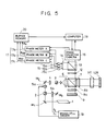
- FIG. 5 is a schematic diagram of the principal part of an optical system according to a second embodiment of the present invention. Like components as those shown in the FIG. 1 embodiment are indicated by like numerals, and an explanation thereof will be omitted.
- an object 11 T to be measured is a plate made of a transparent material.
- the present apparatus measures the uniformness of the material of the object to be measured according to the distribution of the refractive index.
- Reference numeral 10R represents a second reference plane mirror.
- a first light wave having a frequency f1 passing through the beam splitter 7 is made to be a circularly polarized light beam by the X/4 plate 8b, and is incident upon and transmitted through the object 11 T to be measured.
- the light beam reflected by the second reference plane mirror 10R is again incident upon and transmitted through the object 11 T to be measured to return to the original optical path.
- the light wave is then reflected by the polarizing beam splitter 7 to be combined with the reference wavefront, is made to be coherent light by the polarizer 12, and is detected by the photodetectors 15a - 15c and the image dissector camera 16.
- the phase distribution of the heterodyne signal f1 - f2 detected by the image dissector camera 16 in the present embodiment represents the distribution of the refractive index of the object 11 T to be measured in the form of the distribution of optical path lengths at respective portions, that is, the distribution of optical path differences.
- the wavefront aberration q)-(X,Y) corresponding to each portion obtained by expression (2) may be converted into an error in the refractive index by a well-known method according to previously obtained data of the thickness of the object 11 to be measured. That is, in the present embodiment, the refractive index n(X,Y) at each portion may be converted using the following expression: where L is the thickness of the object 11 to be measured, f is the frequency of light for measurement, and C is the speed of light.
- FIG. 6 represents a third embodiment of the present invention.
- an object 11 L to be measured is a lens.
- a reference curved-surface mirror 10W has a reflecting surface having the same shape as the wavefront of the lens 11 L when the lens 11 L forms an ideal outgoing wavefront. Since other components are the same as in the second embodiment, an explanation thereof will be omitted.
- the distribution of the heterodyne signal f1 - f2 detected by the image dissector camera 16 represents twice an error of the deviation of the shape of the wavefront of the spherical wave generated by the lens 11 L from the shape of the reflecting surface of the reference curved-surface mirror 10W. That is, in the present embodiment, an aberration of the wavefront generated by the lens 11 due to deviation from an ideal outgoing wavefront is measured.
- measurement may be performed with removing the influence of the tilt, vibration and the like of the reference plane mirror 9, the second reference plane mirror 10R, the reference curved-surface mirror 10W and the like.
- the three photodetectors 15a, 15b and 15c may be disposed at any positions provided that they are not disposed on a straight line, as described above. That is, they may be disposed in any manner even if they are not orthogonal to one another, provided that they are disposed so as to be able to detect the effect of tilt of the object to be measured, the reference plane mirror and the like in the x and y directions due to vibration and the like.
- a photodetection means having the configuration of a plurality of two-dimensionally arranged elements within one component may also be used.
- An optical heterodyne interferometer generates first and second different frequency light beams.
- the first light beam after irradiating an object to be measured is combinde with the second light beam used as a reference to from a heterodyne signal.
- a first detector detects heterodyne signals from at least three points not in a straight line within a region of the object to be measured.
- a second detector detects heterodyne signals at respective points within the measuring region.
- Optical phase changes of the light beams due to the object to be measured are detected according to the signals obtained from the first and second detectors.
Landscapes
- Physics & Mathematics (AREA)
- General Physics & Mathematics (AREA)
- Spectroscopy & Molecular Physics (AREA)
- Length Measuring Devices By Optical Means (AREA)
- Instruments For Measurement Of Length By Optical Means (AREA)
Applications Claiming Priority (2)
| Application Number | Priority Date | Filing Date | Title |
|---|---|---|---|
| JP18979690 | 1990-07-18 | ||
| JP189796/90 | 1990-07-18 |
Publications (2)
| Publication Number | Publication Date |
|---|---|
| EP0467343A2 true EP0467343A2 (de) | 1992-01-22 |
| EP0467343A3 EP0467343A3 (en) | 1992-07-08 |
Family
ID=16247355
Family Applications (1)
| Application Number | Title | Priority Date | Filing Date |
|---|---|---|---|
| EP19910111969 Ceased EP0467343A3 (en) | 1990-07-18 | 1991-07-17 | Optical heterodyne interferometer |
Country Status (1)
| Country | Link |
|---|---|
| EP (1) | EP0467343A3 (de) |
Cited By (2)
| Publication number | Priority date | Publication date | Assignee | Title |
|---|---|---|---|---|
| EP0520395A1 (de) * | 1991-06-25 | 1992-12-30 | Canon Kabushiki Kaisha | Optischer Heterodyninterferometer |
| GB2579832A (en) * | 2018-12-17 | 2020-07-08 | Compass Optics Ltd | A system and method for inspecting an optical surface |
Family Cites Families (2)
| Publication number | Priority date | Publication date | Assignee | Title |
|---|---|---|---|---|
| US4053231A (en) * | 1975-12-18 | 1977-10-11 | Nasa | Interferometer mirror tilt correcting system |
| US4340304A (en) * | 1978-08-11 | 1982-07-20 | Rockwell International Corporation | Interferometric method and system |
-
1991
- 1991-07-17 EP EP19910111969 patent/EP0467343A3/en not_active Ceased
Cited By (3)
| Publication number | Priority date | Publication date | Assignee | Title |
|---|---|---|---|---|
| EP0520395A1 (de) * | 1991-06-25 | 1992-12-30 | Canon Kabushiki Kaisha | Optischer Heterodyninterferometer |
| GB2579832A (en) * | 2018-12-17 | 2020-07-08 | Compass Optics Ltd | A system and method for inspecting an optical surface |
| GB2579832B (en) * | 2018-12-17 | 2022-03-09 | Compass Optics Ltd | A system and method for inspecting an optical surface |
Also Published As
| Publication number | Publication date |
|---|---|
| EP0467343A3 (en) | 1992-07-08 |
Similar Documents
| Publication | Publication Date | Title |
|---|---|---|
| US4869593A (en) | Interferometric surface profiler | |
| JP3237309B2 (ja) | システムエラー測定方法及びそれを用いた形状測定装置 | |
| US4842408A (en) | Phase shift measuring apparatus utilizing optical meterodyne techniques | |
| JP4188515B2 (ja) | 光学式形状測定装置 | |
| JP3843399B2 (ja) | サブミクロメートル範囲における3次元構造を判定する方法及び装置 | |
| US12228399B2 (en) | Heterodyne light source for use in metrology system | |
| US4346999A (en) | Digital heterodyne wavefront analyzer | |
| JP2000329535A (ja) | 位相シフト干渉縞の同時計測装置 | |
| EP0467343A2 (de) | Optischer Heterodyninterferometer | |
| JPH11337321A (ja) | 位相シフト干渉縞の同時計測方法及び装置 | |
| JPH11194011A (ja) | 干渉装置 | |
| US7466426B2 (en) | Phase shifting imaging module and method of imaging | |
| JP3325078B2 (ja) | 非接触三次元形状計測装置 | |
| JPH055610A (ja) | 計測装置 | |
| JP2595050B2 (ja) | 微小角度測定装置 | |
| JP3466713B2 (ja) | 計測装置 | |
| US12313791B2 (en) | Digital holography metrology system | |
| JPH0719842A (ja) | 表面形状の光学的測定装置 | |
| EP0520395A1 (de) | Optischer Heterodyninterferometer | |
| JP3139862B2 (ja) | 表面欠陥検査装置 | |
| JP2517551B2 (ja) | 位相分布測定装置 | |
| JP3496786B2 (ja) | 位相物体の測定方法および測定装置 | |
| JPH0545140A (ja) | 曲率半径の測定方法及び装置 | |
| JPH085347A (ja) | システムエラー測定方法及びそれを用いた形状測定 装置 | |
| JPS62263428A (ja) | 位相変化測定装置 |
Legal Events
| Date | Code | Title | Description |
|---|---|---|---|
| PUAI | Public reference made under article 153(3) epc to a published international application that has entered the european phase |
Free format text: ORIGINAL CODE: 0009012 |
|
| AK | Designated contracting states |
Kind code of ref document: A2 Designated state(s): DE FR GB |
|
| PUAL | Search report despatched |
Free format text: ORIGINAL CODE: 0009013 |
|
| AK | Designated contracting states |
Kind code of ref document: A3 Designated state(s): DE FR GB |
|
| 17P | Request for examination filed |
Effective date: 19921124 |
|
| 17Q | First examination report despatched |
Effective date: 19931227 |
|
| STAA | Information on the status of an ep patent application or granted ep patent |
Free format text: STATUS: THE APPLICATION HAS BEEN REFUSED |
|
| 18R | Application refused |
Effective date: 19950731 |