EP0467586B1 - Handhabung von Ladegut - Google Patents
Handhabung von Ladegut Download PDFInfo
- Publication number
- EP0467586B1 EP0467586B1 EP91306273A EP91306273A EP0467586B1 EP 0467586 B1 EP0467586 B1 EP 0467586B1 EP 91306273 A EP91306273 A EP 91306273A EP 91306273 A EP91306273 A EP 91306273A EP 0467586 B1 EP0467586 B1 EP 0467586B1
- Authority
- EP
- European Patent Office
- Prior art keywords
- load
- deck
- loading
- pallet
- bogies
- Prior art date
- Legal status (The legal status is an assumption and is not a legal conclusion. Google has not performed a legal analysis and makes no representation as to the accuracy of the status listed.)
- Expired - Lifetime
Links
- 230000003028 elevating effect Effects 0.000 claims abstract description 7
- 239000000725 suspension Substances 0.000 claims description 15
- 230000008878 coupling Effects 0.000 claims description 13
- 238000010168 coupling process Methods 0.000 claims description 13
- 238000005859 coupling reaction Methods 0.000 claims description 13
- 239000012530 fluid Substances 0.000 claims description 6
- 230000035515 penetration Effects 0.000 claims description 4
- 239000000470 constituent Substances 0.000 claims description 3
- 230000000284 resting effect Effects 0.000 abstract description 4
- 238000010276 construction Methods 0.000 description 19
- 230000009471 action Effects 0.000 description 13
- 230000015572 biosynthetic process Effects 0.000 description 8
- 238000013459 approach Methods 0.000 description 6
- 238000003860 storage Methods 0.000 description 6
- 239000000463 material Substances 0.000 description 5
- 230000007246 mechanism Effects 0.000 description 5
- 238000004806 packaging method and process Methods 0.000 description 5
- 230000003068 static effect Effects 0.000 description 4
- 244000288377 Saxifraga stolonifera Species 0.000 description 3
- 229910000831 Steel Inorganic materials 0.000 description 3
- 238000005452 bending Methods 0.000 description 3
- 238000006243 chemical reaction Methods 0.000 description 3
- 230000000295 complement effect Effects 0.000 description 3
- 230000009977 dual effect Effects 0.000 description 3
- 230000005057 finger movement Effects 0.000 description 3
- 238000007667 floating Methods 0.000 description 3
- 230000001965 increasing effect Effects 0.000 description 3
- 238000003780 insertion Methods 0.000 description 3
- 230000037431 insertion Effects 0.000 description 3
- 230000002441 reversible effect Effects 0.000 description 3
- 238000005096 rolling process Methods 0.000 description 3
- 239000010959 steel Substances 0.000 description 3
- 238000012546 transfer Methods 0.000 description 3
- 235000004443 Ricinus communis Nutrition 0.000 description 2
- 239000002131 composite material Substances 0.000 description 2
- 238000005516 engineering process Methods 0.000 description 2
- 230000000670 limiting effect Effects 0.000 description 2
- 238000004519 manufacturing process Methods 0.000 description 2
- 238000005007 materials handling Methods 0.000 description 2
- 239000012528 membrane Substances 0.000 description 2
- 230000002093 peripheral effect Effects 0.000 description 2
- 239000011148 porous material Substances 0.000 description 2
- 230000009467 reduction Effects 0.000 description 2
- 239000004677 Nylon Substances 0.000 description 1
- 230000006978 adaptation Effects 0.000 description 1
- 230000008901 benefit Effects 0.000 description 1
- 230000009172 bursting Effects 0.000 description 1
- 230000015556 catabolic process Effects 0.000 description 1
- 239000011248 coating agent Substances 0.000 description 1
- 238000000576 coating method Methods 0.000 description 1
- 238000002485 combustion reaction Methods 0.000 description 1
- 238000010924 continuous production Methods 0.000 description 1
- 230000001276 controlling effect Effects 0.000 description 1
- 230000036461 convulsion Effects 0.000 description 1
- 238000000151 deposition Methods 0.000 description 1
- 238000011161 development Methods 0.000 description 1
- 230000003292 diminished effect Effects 0.000 description 1
- 238000006073 displacement reaction Methods 0.000 description 1
- 238000004090 dissolution Methods 0.000 description 1
- 238000009826 distribution Methods 0.000 description 1
- 230000005484 gravity Effects 0.000 description 1
- 230000006698 induction Effects 0.000 description 1
- 230000000977 initiatory effect Effects 0.000 description 1
- 238000009434 installation Methods 0.000 description 1
- 230000010354 integration Effects 0.000 description 1
- 230000003993 interaction Effects 0.000 description 1
- 238000005339 levitation Methods 0.000 description 1
- 239000011159 matrix material Substances 0.000 description 1
- 239000002609 medium Substances 0.000 description 1
- 239000002184 metal Substances 0.000 description 1
- 238000000034 method Methods 0.000 description 1
- 230000001483 mobilizing effect Effects 0.000 description 1
- 238000012986 modification Methods 0.000 description 1
- 230000004048 modification Effects 0.000 description 1
- 239000002991 molded plastic Substances 0.000 description 1
- 208000029278 non-syndromic brachydactyly of fingers Diseases 0.000 description 1
- 229920001778 nylon Polymers 0.000 description 1
- 239000004033 plastic Substances 0.000 description 1
- 229920003023 plastic Polymers 0.000 description 1
- 230000001105 regulatory effect Effects 0.000 description 1
- 230000000452 restraining effect Effects 0.000 description 1
- 235000014214 soft drink Nutrition 0.000 description 1
- 125000006850 spacer group Chemical group 0.000 description 1
- 238000003892 spreading Methods 0.000 description 1
- 210000002105 tongue Anatomy 0.000 description 1
- 239000006163 transport media Substances 0.000 description 1
Images







Classifications
-
- B—PERFORMING OPERATIONS; TRANSPORTING
- B65—CONVEYING; PACKING; STORING; HANDLING THIN OR FILAMENTARY MATERIAL
- B65G—TRANSPORT OR STORAGE DEVICES, e.g. CONVEYORS FOR LOADING OR TIPPING, SHOP CONVEYOR SYSTEMS OR PNEUMATIC TUBE CONVEYORS
- B65G67/00—Loading or unloading vehicles
- B65G67/02—Loading or unloading land vehicles
- B65G67/04—Loading land vehicles
- B65G67/20—Loading covered vehicles
Definitions
- This invention relates to material(s) handling and is particularly, but not exclusively, concerned with the unitary or 'one-shot' handling relatively large, bulky, cumbersome or multi-component loads as a single entity.
- load' embraces any kind or form of material, whether single or multiple items, packaged or loose - without particular restriction upon overall volume, configuration or weight.
- the term 'handling' embraces any action or treatment which it is desired to apply to a load, or constituent parts of the load - and indeed the very initial load formation and subsequent load dissolution or dismantling.
- Loads may be prepared ready for handling by virtue of their 'packaging profile', including a pre-assembled stack of individual component subsidiary loads, but the stack, whilst representing in its entirety the overall load to be treated or handled as a whole, may not itself have the inherent robust nature or integrity to facilitate such handling as a single entity.
- the load may be loose stacked cartons.
- the invention is concerned in some (but not necessarily all) of its aspects with the handling of a load in its entirety, including the transfer of a previously assembled (multi-component) load into a pre-defined load space, such as a (vehicle) container, which is either unmodified or has minimal modifications or adaptations to receive the load.
- a load space such as a (vehicle) container
- An example would be the loading or unloading of an entire (eg containerised) vehicle load in a single operation.
- a remote (ie not an integral part of the vehicle) loading or unloading facility for such 'single-phase' operation is desirable, for use with different vehicles.
- load handling is a 'temporary' special case of materials handling, ie a 'given' or prescribed amount of material to be handled at a given time, on a given occasion, or over a given time span; and generally a case where external restrictions or limitations in mechanical practicalities associated with the nature of the load itself, are placed upon the volume, configuration or weight of the material to be handled at any such one time.
- material may be produced in a form which suits, or is a compromise between the requirements of the producer, along with any interim stockists and ultimate consumer, for the intended market, but may not be particularly suited to the available external carriage or transport facilities, which are generally outside the control of the producer.
- a 'container' has prescribed shape and volume upon a given base floor area, along with a maximum loaded weight, and may be physically enclosed with side and end walls and a roof, or some of these may be omitted, with a limiting case of a simple load platform with some tie down and stacking points.
- small unit loads such as cans of foodstuffs or drink may have to undergo several successive packaging steps, eg cartons or crates, stacked upon pallets and shrink wrapped for stability, to fill a container - ie they cannot economically be loaded individually, and even when grossed into larger multiple units, these are still much less than an individual container capacity.
- Both these load examples are characteristically static, or with no inherent mobility, whether in the packaging or otherwise.
- a container has predetermined associated handling costs, regardless of its actual contents, ie (subject to special commercial tariff arrangements) an empty container costs as much to handle and transport as a full container.
- a container generally represents a bulk load capacity to be filled as completely as possible, by a typically multi-component or fragmented load, minimising wasted voids and within the prescribed weight limitations - and also without undue packaging, which represents a load 'denial' (or wasted additional load opportunity) and an unproductive associated expense overhead.
- the handling space III must also be compatible with the available load capacity II - ie the handling facility must be able to fit physically, at least in part into that capacity, in order to introduce and withdraw the load in relation thereto.
- the load handling space must align closely with the minimised difference between I and II - ie with minimal wasted load capacity, the load handling must still be able to operate, from start to end of the loading sequence.
- the handling device may have to fit within the container. Not least because of the inherent fragmented nature of many, if not most, container loads - ie the container load capacity is many times an individual load component - it is commonplace to introduce the load components individually, as what will hereinafter be referred to for convenience as multiple 'subsidiary' loads.
- Trucks or trolleys are typified by independently-mobile fork-lift trucks and pallet trolleys - usually restricted to a single, or a relatively few component (eg palletised) loads, at least in relation to an overall container capacity.
- European Patent Application No. 0 133 042 teaches an elevatable track-running, load handling trolley variant.
- European Patent Application No. 0 000 321 teaches an elevatable mobile roller conveyor variant.
- Both of these handling device categories have been adapted for containerised loads, with a uniform overall load profile, which facilitates subsequent storage and handling - ie a larger stack of containers can be formed and vehicles and load handling equipment, such as cranes and side-loader lifts, may have standardised fittings to receive such containers.
- Such uniformity may be extended within the container, by adopting subsidiary component loads themselves also of a (lesser) uniform profile, by palletisation or even 'miniature' containers.
- Palletised loads are generally stackable, so that any irregularity of the individual load items does not undermine the regularity of the overall load profile - although there may necessarily be voids within the container.
- any vehicle with a predefined load space and load volume imposes corresponding constraints upon the nature of its load capacity - ie in short, the load must be tailored to fit the vehicle/container.
- the load can be broken down into relatively small and regularly shaped components, then - given enough time, skill and patience, and some discretion in load component selection - virtually the entire load space can be filled, at least manually.
- an individual (palletised) load stack eg from a collection of cartons of individually known configuration, fed to by a conveyor, from a continuous production source or an intermediate stockpile, to a palletised load formation station, where they are deposited in succession upon a palletised floor until a stack of desired proportions and weight has been formed.
- These cartons may be coded, eg by bar coding, to reveal their identity to a selection and loading mechanism.
- the thus palletised load may be 'integrated' or formed into a unitary collection, eg by shrink wrapping, to give the palletised load stability in subsequent handling.
- Palletised loads lend themselves to handling by conventional relatively small-scale, general purpose un/loading vehicles, such as fork lift trucks, which can readily be used to fill long vehicle open-sided containers or decks from the exposed accessible vehicle (longitudinal) sides, side cover sheets, doors or shutters then being closed to conceal and protect the load or the load covered overall by a tarpaulin and roped or strapped in position.
- conventional relatively small-scale, general purpose un/loading vehicles such as fork lift trucks, which can readily be used to fill long vehicle open-sided containers or decks from the exposed accessible vehicle (longitudinal) sides, side cover sheets, doors or shutters then being closed to conceal and protect the load or the load covered overall by a tarpaulin and roped or strapped in position.
- fork lift trucks may be used only to introduce the load at that end, with subsequent movement being effected manually, albeit with the assistance of bearing surfaces on the vehicle floor or individual pallet trucks.
- pallet is used herein generally to embrace any from of platform or other ancillary load support, including load suspensions or side braces, upon which a load may be rested or otherwise mounted for subsequent storage and transit.
- Conventional pallets as an underside or platform floor, are typically of a spaced timber planking lattice construction, in order to support a load for storage and transit.
- the pallet provides a ready means of grasping the load and bearing its weight, for example by using the support arms/tines/prongs of a fork lift truck to locate through the pallet depth.
- the pallet has either a twin opposed reversible slatted deck surface with spaced intervening bearers, or a single deck with support ribs.
- a vehicle container load deck may have integral bearing surface incorporating rollers spaced over the load deck for moving parts of the load around the deck, with means to lock or withdraw those rollers into an inoperative (non-load contacting) condition.
- UK Patent No. 2,126,189 teaches one such a 'bespoke' roller deck, for integration with a vehicle or container floor.
- a similar roller load deck may be used at the un/loading station for the assembled load ready for un/loading.
- the individual load components can then be rolled, either singly or as a group, from the assembled stack on to the (vehicle) container.
- roller decks also incorporate a drive mechanism, such as a friction-grip slipping chain or belt, so that the deck combines the functions of a conveyor.
- a drive mechanism such as a friction-grip slipping chain or belt
- continuous runs of power driven decks may be used to transport loads, typically palletised so that a pallet may engage the drive mechanism, over long runs.
- This load deck typically of the order of some 12 metres (40 feet), is a critical factor in loading from one of the narrow ends.
- such a full load could advantageously be made up of standard pallets, typically 1000 mm x 1200 mm in surface area, but handling a fully palletised load at one time (rather than in successive 'bites' or steps) has not hitherto proved feasible.
- DE-B-2706986 teaches a variant of the bespoke rolling element deck loader, using an array of loading carriages (imitating fork lift lines) intercoupled in tandem in parallel rows and running on a continuous track between a deck or loading/unloading station and a vehicle container.
- US 4844681 teaches another 'constrained' multiple load carriage and guide track arrangement.
- a desirable capability is the 'penetration' of standard so-called 'base perimeter' pallets adapted for the tines of a fork-lift truck.
- the necessary multiple pallet penetration, and riding over the obstacles of the pallet base frames is not achievable with such previous multiple interlinked carriage arrangements.
- a load handler incorporating a plurality of mobile load support carriages inter-coupled in tandem rows to run in a track upon a load deck between spaced load handling locations at opposite ends of the load deck, each carriage being configured as a shallow elongate finger to penetrate beneath a pre-assembled load, and load elevating and lowering means; characterised by steering means between carriages, for lateral carriage guidance upon departure from the track at a load handling location.
- a releasable drive coupling may be incorporated for the intercoupled carriages, whereby the carriages may exit and enter either end of the track, to allow penetration and withdrawal at either load handling location.
- the load handler steering means could comprise a carriage coupling with a displaceable member reacting between and for relatively articulating successive carriages.
- the carriages of the load handler could incorporate underslung bogies with runners, end sets of which are displaceably mounted to ride over obstacles as a carriage suspension.
- the load handler may incorporate intermediate bogies between end bogies said intermediate bogies being retractable into a position nesting within the embrace of the carriage frame, the load elevating means being operative to extend said bogies away from the carriage frame.
- the load may be elevated and lowered by means of a series of co-operatively inter-coupled individual inflatable fluid bags within the carriages and operative between the bearer for the bogies and the carriage frame.
- the load handler may utilise a master load support surface upon which the load constituents are deposited and which is acted upon direct by a load support carriage.
- the load handler could comprise a mobile self-contained load deck support beam incorporating drive means for moving an array of load fingers mounted thereupon along a guideway in the beam surface.
- Unloading is generally the reverse of loading, so the expression 'un/loading' embraces the corresponding loading and reversed unloading functions, whether of the whole load or some (selected lesser) part thereof.
- Such a loading assembly would in principle be capable of loading an entire full sized container in a single operation from one (smaller) end alone, with the loading deck subsequently withdrawn for re-use on another subsequent container loading operation.
- the invention obviates the need for a specially adapted loading floor for each individual vehicle or load container or deck.
- the latter is disposed upon a retractable load deck 12, itself mounted upon a generally flat support (platform) surface 19 at an un/loading (collection, parking or distribution) station.
- the load 16 may rest, ready for handling, directly upon the support surface 19 through the contact therewith of the pallet legs or underside support ribs 21 (see particularly Figure 7).
- the load deck 12 may then simply sit upon the support surface 19 marginally clear of, or 'tentatively engaging', the underside of the (palletised) load 16 or the master pallet 18, if present.
- the master pallet 18 may thus perform a valuable ancillary unifying or consolidating function for the overall load 16 in relation to the load deck.
- the load deck is itself capable, through intervening rotational bearing runners generally indicated at 13, of (at least linear transitional) movement over and in directions generally parallel to the support surface 19, as indicated by arrow 11.
- the load deck 12, with the load 16 supported thereupon in its entirety can be moved from over the load (collection) station support surface 19 to another location altogether - such as into a vehicle container 42 (as shown in Figure 2), if the container deck 43 is at approximately the same level.
- the overall depth of the load deck 12 is kept to a minimum, so that the overall load height, and thus vehicle container load capacity, is not unduly diminished.
- the load deck 12, or at least its upper surface, may be elevated or extended, as indicated by arrows 15, in an upright direction transverse thereto, in order to engage the underside of the (palletised) load 16 and lift it clear of the support surface 19, to allow corresponding (eg linear transitional) movement of the load 16 as a unitary whole .
- Figure 2 shows in more detail the construction of a retractable load deck in which an (optional supplementary) upper (bearing) surface 22 thereof incorporates retractable and/or lockable (ie to inhibit rotation thereof) upper bearing rollers 23, spaced uniformly across the area thereof, in order to provide a continuous 'mobile' bearing surface 22 for the load 16, thereby enabling movement of the load 16 as a whole in relation to the load deck - thus facilitating its retraction from underneath the load 16, as described later.
- an (optional supplementary) upper (bearing) surface 22 thereof incorporates retractable and/or lockable (ie to inhibit rotation thereof) upper bearing rollers 23, spaced uniformly across the area thereof, in order to provide a continuous 'mobile' bearing surface 22 for the load 16, thereby enabling movement of the load 16 as a whole in relation to the load deck - thus facilitating its retraction from underneath the load 16, as described later.
- a corresponding retractable and/or lockable lower bearing surface 24 is provided on the underside of the load deck 12, by means of spaced lower rollers 33, to promote the movement of the load deck 12 as a whole over the support surface 19, while carrying the entire burden of the overall unitary load 16.
- the upper rollers 23 could be dispensed with, in favour of retractable lower rollers 33, this being the preferred configuration adopted for the embodiments of Figures 10 onwards, as described later.
- a supplementary drive facility for example a friction contact/slip chain or belt (not shown) may also be integrated with the bearing surfaces 22, 24 in order to generate and promote relative movement over those surfaces.
- the master pallet 18 is depicted under the entire suspended load 16 and surmounted by an array of multiple adjacent subsidiary pallets 17, each supporting subsidiary component loads 26, which cumulatively form the overall load 16.
- an external coupled wire hawser or chain pulley or sprocket drive system may be employed.
- the load 16 is deposited upon the container floor 43 simply by lowering of the rollers 23 of the upper bearing surface, so that the load 16 rests upon the pallets 17 and master pallet 18.
- Complementary ribs could be provided on the vehicle floor 43 aligned with underside pallet support ribs 21(see Figure 7) to promote the clearance between the underside of the pallet and the vehicle floor 43, thereby facilitating retraction of the load deck.
- the 'released' load deck 12, relieved of the load 16 can simply by withdrawn by sliding from underneath the load 16, initially over the vehicle floor 43 and thence progressively over the original loading station support surface 19, ready for the next load 16.
- the reverse procedure is adopted for unloading the vehicle container.
- This facility could also allow the load deck 12 to be introduced under a pre-assembled load 16 in the first instance, without having to assembled the load 16 upon the deck 12.
- the 'depth compressibility' eg by the lowering provision of the upper bearing surface 22, of the load deck 12 itself, is also a critical factor in creating a working clearance between the underside of the load 16 and the vehicle floor 43, and more importantly, between the underside of the load 16 and that upper bearing surface 22 - given that the lower bearing surface 24 needs to run along the vehicle floor 43, in order to withdraw the load deck 12 from the vehicle container 42.
- Figure 3 depicts an alternative so-called 'magic carpet' construction, in which a flexible 'bearing sheet' 28 combines the functions of both the load deck 12, integrated load movement bearings and a master pallet 18.
- Both upper and lower surfaces of the sheet 28 are self-lubricating, so that it may be withdrawn from under the load 16 by free sliding contact between the underside of the load 16 and the vehicle floor 43.
- the sheet 28 is sufficiently flexible that it may be coiled on a drum 29 when retracted.
- Both insertion and withdrawal of the sheet 28 can be implemented by powered rotation of the drum 29.
- a laminated or multi-layer sheet construction may be employed, with say an outer resilient porous membrane, into which compressed air may be fed and subsequently slowly and continuously bled from external surface pores to achieve an air bearing, with a marginal clearance from the surface of the sheet 28.
- a combination of low friction surface coating, low contact area surface profile (eg nylon mesh) to the sheet 28 and such a surface air bearing (eg between the mesh pores and/or from the mesh strands themselves) could be used to 'free' even heavy loads sufficiently to allow the necessary sheet movement, particularly with an initial 'jerk' or impulse action.
- the underside of the load 16 would need a suitable complementary (preferably smooth sealed) profile.
- a parallel to such a 'magic-carpet' foldable load deck may be achieved by a development of the load (deck) finger construction of Figure 10 onwards, as described later, and in which a limiting case of relatively short finger 'stubs' are close-coupled as a continuous flexible track - eg in the manner of a track-laying vehicle.
- Such stub fingers could be reeled in coil mounted upon, say, a cylindrical sprocket hub drum, which would transmit the drive.
- the drum could be located below a load support surface, with the finger track accessible through an aperture, from which it could be introduced under the load and withdrawn therefrom, without occupying additional space at the side of the drum. This would keep the loading bay size to a minimum representing the actual load size.
- FIG. 4A and 4B depicting respectively the raised and lowered deck conditions.
- the upper deck bearing rollers 23 are retractable by means of continuous fluid-filled support bags 38, whose outer sheathes 39 engage the undersides of the rollers 23 and seal an internal fluid chamber.
- the fluid chambers of the bags 38 can be selectively pressurised, in order to inflate the bags 38 and raise the rollers 23 (as illustrated in Figure 4A), or deflated to lower the rollers 23 (as illustrated in Figure 4B).
- Figure 5 shows the load deck 12 in the raised condition and bearing the full weight of the load 16, under insertion into a vehicle container 42.
- Figure 6A shows an alternative retractable bearing roller arrangement for the load deck 12, in which a triangular braced carriage frame 92 carries an array of an upper roller 63, at its upper apex, contacting the underside of the load 16, and a depending pair of lower rollers 73, 83, which remain in contact with the un/loading station support surface 19.
- the lower horizontal leg of the frame 92 incorporates an intervening pneumatic or hydraulic strut 91, extensible or retractable to vary the spacing between the lower rollers 73, 83 and thus the degree of 'collapsed' triangulation of the frame 92 and the height of the upper roller 63 in relation to the lower pair of rollers 73, 83.
- Figure 6B shows in transverse section the variable height bearing action of the roller assembly 63, 73 and 83.
- Figure 7 shows, in side elevation/transverse section a pair of standard sized subsidiary pallets 17 upon a master pallet 18 of corresponding constructional form.
- Figures 8A and 8B show, in plan view, another relative configuration of the load deck 112 and master pallet 118, to facilitate the introduction of a load deck underneath the load, albeit along a single axis, without increasing the load height.
- Complementary multiple (comb-like) interfitting tongues or limbs 65 and 75 on the load deck 112 and master pallet 118 respectively are laterally offset, to allow feeding and withdrawal of the master pallet 118 and a load 16 supported thereupon, from the un/loading station 19 into a delivery station within the vehicle container 42.
- Figure 8A illustrates the (vehicle container 42) unloaded condition, with the master pallet118 nested with the load deck 112, and Figure 8B indicates the loaded condition, with the master pallet 118 resting upon the vehicle container floor 43 and the load deck 112 withdrawn.
- Figures 9A and 9B are the corresponding side elevational views to Figures 8A and 8B respectively.
- a diversity of power sources including electric, mechanical (including internal combustion engines), pneumatic and hydraulic may be used singly or in combination, to operate the mobile retractable support means or load deck.
- a master pallet may be fabricated in several component pieces to allow disassembly to facilitate removal and re-installation.
- the load deck 12 could be mounted on jacking legs (eg a scissor-action type) to allow loading of stacked containers 42, ie with their load decks 43 above the loading station surface 19.
- jacking legs eg a scissor-action type
- the bearings on the load deck 12 could be disposed to allow transverse or longitudinal un/loading, or any combination thereof, for greater operational flexibility.
- a bulk load 150 comprises a rectangular matrix or grid (pallet) array 140 of abutting or marginally-spaced individual subsidiary palletised load components 110, using standard pallets 125.
- the individual pallet 125 may be square, in which case typically 1000 x 1000 mm (with a 5 mm tolerance), or rectangular, in which case typically 1000 x 1200 mm, with an overall pallet height or depth of 162 mm and a through gap of 95 mm on one opposite pair of sides and 120 mm on the other pair of opposite sides.
- Figure 18 shows a typical so-called 'base-perimeter' pallet 115 construction, in which a series of spaced slats 146 form one (eg upper) support platform, with a corresponding opposite (eg lower) support platform formed of similar slats 148, marginally spaced therefrom by a series of corner blocks 141 and intermediate side and centre blocks 142.
- the 'through'-passages 147 are shallower than the through passages 145, the differences for example being of the order of 95 mm as opposed to 120 mm.
- the lower bracing slats 149 represent a surface obstruction (typically some 25 mm deep) to the entry of the runners 124 of the load fingers 120 and for this reason the end runners 124 are specially configured as bogies incorporating 'jockey' wheel sets 174, 175 (described in more detail in relation to Figures 20 and 23), either trailing or leading according to the direction of finger movement.
- the end bogies 174, 175 may ride over the successive slats 149, as depicted in Figures 24A through 24C.
- the intervening runners 124 are configured as wholly retractable intermediate bogies 176 within the load fingers 120, to minimise the interaction with the pallet slats 149 during insertion of the load fingers 120 through the pallet passages 145 or 147.
- intermediate bogies 176 are not normally 'deployed' during the unloaded condition of the load fingers 120, which rely until loading solely upon the end bogies 174, 175.
- the particular pallet assembly 140 depicted - which admits of considerable variation according the 'receiving' load capacity - represents twelve pallets 125 in length by two pallets 125 in width - that is a total of twenty four pallets 125 - which are moved as a unitary whole load 150 into a container (unshown in Figure 10, but 190 in Figures 11-17).
- the pallet array 140 Corresponding to the pallet array 140 is an array 130 of loading fingers 120 arranged in four generally parallel rows 112, 113, 114 and 115, each of five individual load support 'fingers' 120, close-coupled in tandem.
- the rows 112, 113, 114 and 115 of load fingers 120 are aligned with corresponding aligned through-passages 116, 117, 118 and 119 respectively in the 'queued' sequential array 140 of pallets 125.
- the individual load fingers 120 are mobile upon (surface-contact) runners (or low-friction skids) 124, described in more detail in Figures 19 though 24, and can traverse longitudinally - and to a limited extent track transversely, by means of a steering facility shown in Figure 27. This could enable the fingers 120 to follow a (shallow) curved path if so desired.
- This load finger 120 configuration is adapted for mobilising an otherwise essentially static or immobile load 150 resting passively upon a support surface 170.
- the load 150 - whilst possibly not enjoying great manoeuvrability in a confined space - may nevertheless have some inherent mobility, and may even incorporate runners raising it clear of the support surface. In such situations the loading fingers 120 may provide additional freedom of movement and the drive facility for initiating such movement.
- Such mobilisation may require clearing the bulk of the load 150 from a support surface 170 - and this in turn generally implies some lifting or elevation of the load 150 and a load supporting span between localised points of rolling and/or sliding surface contact.
- the load fingers 120 desirably incorporate such a load lifting capability, deployed as necessary.
- the load fingers 120 run initially upon a load (support and drive) deck 160, which itself may be provided with some freedom of movement for adjusting loading alignment, as shown in Figure 25.
- vehicle load decks 191 particularly for articulated tractor and trailer combinations, may be canted slightly upwards from the rear axle to the tractor cab.
- one end of the load deck 160 may be coupled to the vehicle deck 191, in order to move with it, including minor (chassis runners) twisting distortion and vertical displacement, whilst the other end is pivotally mounted upon a stand.
- mechanical (eg screw) or hydraulic (eg telescopic piston-in-cylinder) lifting jacks may be deployed to adjust the 'approach angle' and orientation of the load deck.
- the entire load deck 160 could be mounted for transverse translational movement, for example between successive adjacent loads and loading stations. Some form of lateral guideway or rail may be provided for this. Alternatively, a simple ground-braced static load deck 160 may be employed.
- Figures 19, 20, 21 and 23 show an individual load finger 120 fabrication from folded steel sheet forming a u-section trough, with underside cross-bracing around apertures receiving bearing runners 124, grouped in pairs of twin wheel axles, or bogies 174, 175 and 176.
- Figure 21 details an intermediate bogie 176 construction, in which a pair of spaced axles 164, 166, with associated wheel sets 163 and 165 respectively, are carried by side arms 194, 195 depending from the bogie top plate 178.
- an inflatable longitudinal bag 185 Between the bogie top plate 178 and the underside of the finger top plate 131 is sandwiched an inflatable longitudinal bag 185.
- intermediate bogies 176 perform the primary finger and thus load lifting function and distribute the lifted load gross weight in the elevated condition.
- the remaining bearing runners 124 and indeed the only ones operative outside load lifting, comprise bogies 174, 175 at opposite ends of the load finger.
- the bogies 174, 175 are mounted upon a spring leaf suspension detailed in Figure 21, for general rolling surface contact when the load finger 120 is unloaded, for example when it is being inserted into and withdrawn from a pallet 125.
- the construction of the bogies 174, 175 corresponds generally to that of the intermediate bogies 176 of Figure 21, except that the spaced leaf springs 186 are mounted in the opposite sense to the springs 177 - that is to bias the bogies 174, 175 downwardly away from the inflatable bag 185.
- the jockey wheels 174, 175 are alternatively leading or trailing.
- Some degree of limited castor action may be incorporated so that the wheels are generally self-aligning with respect to the direction of movement. It is these same 'jockey' wheels that are specially mounted for clearing ground obstructions.
- the leading ends of at least the outermost load fingers 120 are provided with a tapered nose cone 143, which may also incorporate steering and position sensing for controlling the finger movement in relation to the load and the load movement itself once collectively borne by the coupled fingers 120.
- Successive fingers 120 are connected by a resilient tie plate 121, which allows some freedom of relative finger movement, but introduces some conformity or restraint, tending to maintain the overall alignment of the fingers 120.
- Finger alignment is also promoted by incorporating a series of spaced parallel guide rails or tracks 152, 153, 154 and 155 in the load deck 160, which locate between the wheels of each bogie axle set, and with intervening slots through which access is given to corresponding drive chains 156, 157, 158 and 159, running over sprockets 262, 263, 264 and 265 mounted upon a common drive shaft 267 to an electric drive motor 269 through a reduction gearbox 268.
- Each load finger 120 is to some extent self-contained, at least in terms of mobility and load elevation, apart from the power source, which is introduced by a mobile traveller coupling described later.
- the load finger 120 is utilised as a form of carriage, in a train of carriages formed by the load fingers collectively in a row - and of which there are several (in this case four) in parallel formation, and sharing a common drive, to achieve the desired driving torque and load traverse speed.
- More esoteric drives may be used, such as linear induction motors possibly integrated with some form of magnetic levitation.
- the load finger configuration is to some extent determined by considerations attendant with the load palletisation, and in that regard a load finger of convenient operational proportions is achieved by adopting a length sufficient to accomodate two pallets in tandem.
- the load finger width and height is prescribed by size and proportion of the available apertures in the pallet side depth.
- load mobility is achievable by introducing a (single) bearing surface on the underside of the fingers - although additional (eg retractable) runners may be incorporated on the upper side of the load fingers.
- individual finger elevation is achieved by an internal inflatable pneumatic (ie air) bag 185, which bears against the undersides of individual wheel bodies 173.
- inflatable pneumatic (ie air) bag 185 which bears against the undersides of individual wheel bodies 173.
- variable ride-height and suspension movement of an intermediate bogie 176 is depicted, including that upon encountering a ground obstacle 193, such as in particular the ground engaging underside bracing rib of a pallet.
- an intermediate bogie 176 is shown in its fully elevated or retracted position entirely within the frame embrace of a load finger 120, so that the overall depth of the finger is not increased locally thereby. This is important when seeking to feed the load finger through a restricted opening, such as an 'under-pallet' gap, as discussed elsewhere.
- the intermediate bogie 176 is shown in its fully lowered or extended condition, with the wheels 163, 165 in contact with a support surface 200.
- This extended bogie condition is achieved by (fully) inflating the longitudinal air bag 185, until it fills a larger part of the internal depth of the load finger 120 and if necessary until the bogie frame 178 abuts the edge flanges 133, as a physical limit stop.
- the spring mounting of the intermediate bogie 176 against the air bag 185 combines to afford a limited suspension cushioning action, which will accommodate some longitudinal and lateral 'rocking' motion for riding over ground obstacles, in a manner corresponding to that of the leading and trailing end bogies 174, 175, as described elsewhere, in particular in relation to Figures 23, 24B and 24C.
- Figure 24A shows an end bogie 174, 175 in normal ground engagement until encountering an obstacle 199 (such as a pallet bracing slat), whereupon, as depicted in Figure 24B, the lead wheel pair simply rides over the obstacle with a jockey wheel action, followed, as depicted in Figure 24C by the trailing wheel pair.
- an obstacle 199 such as a pallet bracing slat
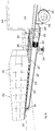
- Figure 25 shows a preferred construction of adjustable or 'floating' load deck 220, incorporating a pivot mounting 226 at one end, with a 'free' opposite end adjustable in height by a mechanical screw and/or hydraulic jack 224 reacting between the load deck 220 and a support surface 225.
- Such height adjustment enables alignment of the upper load transfer surface 228 of the loading deck 220 with the load deck 231 of a container 230 mounted upon a trailer 231 of a road vehicle 240.
- a physical coupling 229 may be provided between the outer end of the load deck 220 and the vehicle chassis or container floor 232, so that they remain aligned, even under vehicle suspension deflection with the varying vehicle load.
- the load deck 220 may be aligned in the optimum practical way with it.
- the load deck 220 may be movable, (eg transversely of its length) between (successive adjacent) loading stations, where vehicles or parked loads ready for transit are set.
- end pivot support 226 may itself be mounted upon a rail or guide way and the undersides of the jacks 224 may incorporate (castor) runners or wheels.
- the entire load deck 220 could be rotatably mounted upon a turntable, with loads and containers arranged radially around it.
- load deck 220 mobility is not a major consideration in a particular loading situation, then the load fingers 280 themselves may be afforded additional freedom of movement - even ultimately independently of any load deck guideway or drive.
- the load fingers 280 could incorporate their own drive and guidance, as a specialised form of AGV (automatically guided vehicle), either with an on-board energy store, such as a battery or hydro-pneumatic pressure reservoir, or an umbilical connection with a power source.
- AGV automated guided vehicle
- a rectangular intersecting lattice or grid of pre-fabricated structural plates defines a series of spaced parallel guideways 249 with underlying aligned (chain) drive passages 248 accommodating an individual continuous chain loop (not shown) for corresponding rows of load fingers 280.
- Such a hollow beam affords torsional and longitudinal bending stiffness, without undue overall weight penalty and can be entirely fabricated and the internal drive components fitted off-site in controlled factory conditions - with delivery on-site being achievable simply by carrying the load deck upon a trailer whose overall dimensions and proportions correspond broadly thereto with minimal overhang.
- the upper flanges 263, 264 provide convenient mounting surfaces for the upper deck panels 228 and between them are spaced side rail flanged strip members 245, 246 around which the runners 124 of the load fingers 280 embrace and through which a drive and pneumatic services for the internal air bags 285 is provided, as discussed later.
- Mobile detachable drive couplings or travellers may be employed to bridge the gap between the concealed drive chains and the load fingers 280, and these may also couple the other services, such as a pneumatic supply for the load finger air bags and steering and an electrical supply for the load finger position sensing.
- Such a traveller may move alternatively between opposed chain drive sprockets at the extremities of movement, that is at opposite ends of the load deck 220.
- Two travellers may be employed for each row of fingers 280, one at each end mounted to engage the associated drive chain for a cycle of movement to one side of the load deck and then back over the load deck, whereupon that traveller disengages and the temporarily parked traveller at the opposite end engages and takes over for movement to the opposite side of the load deck and then back over the load deck - whereupon drive coupling reverts to the original traveller, an so on.
- the longitudinal stringer panels 241, 242 are braced transversely by upright cross-panels, such as 266, and the upper deck panels 228.
- a corresponding lower deck platform could also be provided, with access apertures for the chain drive passages 248.
- a bell housing 253 coupling a gearbox 252 with an electric drive motor 251.
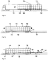
- Figures 25 and 26 depicts the loading of an international standard container 230, with a capacity represented by a rectangular assembled gross load 250 of multiple individual subsidiary loads 260 upon an rectangular array of standard pallets 270, each in this case stacked individually several (eg two or three) deep with subsidiary loads 260.
- the load is two pallets 260 in width by, in this case eight, but possibly eleven or twelve as with the preliminary general example of Figures 10 through 17.
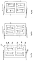
- Figures 27A through 27C show the principles of a steering, guidance of alignment facility for the load fingers 280 - and in particular the 'lead' fingers for a given direction of (linear translational) movement - and which may thus become the trailing ends when the drive is reversed.
- some means of maintaining the integrity of the load finger running line, and to make minor adjustments in load movement is desirable, particularly if the load is to be placed in a confined load capacity space, such as a container, where there is minimal marginal space between the load of a fully loaded container and the inside container walls, with minimal intrusion by the load fingers in the residual vertical clearance between load and container roof.
- Figure 27A shows a coupling 310 between successive load fingers 280 (the end of only one of which is shown). This replaces the normal resilient flat plate interconnecting link 121.
- the coupling 310 incorporates a rectangular box frame 282 housing a pair of resilient bushes, each comprising deformable rubber diaphragms 286, 287 clamped into a metal mounting plate housing 283, 284 respectively and inflatable or at least tensionable selectively by air pressure, in order to provide a reaction between the mounting blocks 283, 284 and the outer frame 282, which is in turn transmitted to an end plate 281 in the frame of the load finger 280.
- the dual bush configuration may be replaced with a single offset bush reacting against an opposed hinge or another multiple bush array.
- a open-bottom or so-called 'wing' pallet construction such as the moulded plastics Euro-pal style, in which a pallet base is supported upon spaced stubby legs without a peripheral bracing skirt.
- Such Europallets are typically 800 mm by 1200 mm in surface area, enabling a load three pallets (at 800 mm) in width - totalling 2400 mm - for which six rows of load fingers might be employed.
- individually mobile pallets such as 'roll cages' may be handled collectively.
Landscapes
- Engineering & Computer Science (AREA)
- Aviation & Aerospace Engineering (AREA)
- Mechanical Engineering (AREA)
- Loading Or Unloading Of Vehicles (AREA)
- Pallets (AREA)
- Fats And Perfumes (AREA)
- Auxiliary Methods And Devices For Loading And Unloading (AREA)
- Transition And Organic Metals Composition Catalysts For Addition Polymerization (AREA)
- Ship Loading And Unloading (AREA)
- Chain Conveyers (AREA)
- Warehouses Or Storage Devices (AREA)
- Medicines That Contain Protein Lipid Enzymes And Other Medicines (AREA)
Claims (8)
- Ladeguthandhabungsvorrichtung (225), mit mehreren beweglichen Ladeguttragwagen (120, 280), die hintereinander in Reihen (112, 113, 114, 115) so aneinandergekoppelt sind, daß sie auf einem Ladegutdeck (220) in einer Spur (249) zwischen beabstandeten Ladeguthandhabungsorten (227, 240) an gegenüberliegenden Enden des Ladegutdecks laufen, wobei jeder Wagen (280) als flacher, länglicher Finger konfiguriert ist, der unter vormontiertes Ladegut (250) dringen kann, und einem Ladeguthebe- und -senkmittel; gekennzeichnet durch ein Lenkmittel (310) zwischen Wagen zur seitlichen Wagenführung bei Verlassen der Spur an einem Ladeguthandhabungsort.
- Ladeguthandhabungsvorrichtung nach Anspruch 1, mit einer freigebbaren Antriebskupplung (300) für die aneinandergekoppelten Wagen (280), wodurch die Wagen an einem der beiden Enden der Spur (249) ein- und austreten können, so daß das Eindringen und das Zurückziehen von Ladegut an einer der beiden Ladeguthandhabungsorte (227, 240) gewährleistet wird.
- Ladeguthandhabungsvorrichtung nach Anspruch 1, bei der das Lenkmittel (310) eine Wagenkupplung (282, 283, 284) mit einem verschiebbaren Glied (286, 287) umfaßt, das zwischen aneinander angelenkten aufeinanderfolgenden Wagen (280) und für diese reagiert.
- Ladeguthandhabungsvorrichtung nach Anspruch 1, bei der die Wagen (120, 280) untergehängte Drehgestelle (174, 175, 176) mit Laufgliedern (124, 163, 165) enthalten, wobei Endsätze (174, 175) davon verschiebbar angeordnet sind, so daß sie als Wagenaufhängung Hindernisse (200) überfahren.
- Ladeguthandhabungsvorrichtung nach Anspruch 4, mit Zwischendrehgestellen (176) zwischen Enddrehgestellen (174, 175), wobei die Zwischendrehgestelle (176) in eine Position zurückgezogen werden können, die sich in der Umfassung des Wagenrahmens (131) befindet, wobei das Ladeguthebemittel (185) die Drehgestelle (176) aus dem Wagenrahmen (131) herausfährt.
- Ladeguthandhabungsvorrichtung nach Anspruch 5, bei der das Ladeguthebe- und -senkmittel (185) eine Reihe von aneinander wirkgekuppelten, einzelnen, aufblasbaren Fluidbeuteln (185) in den Wagen (120, 280) umfaßt, die zwischen einer Tragvorrichtung (178) für die Drehgestelle (176) und dem Wagenrahmen (131) wirken.
- Ladeguthandhabungsvorrichtung nach Anspruch 1, bei der eine Ladeguttraghauptfläche (18) verwendet wird, auf der die Ladegutkomponenten (16) abgelegt werden und auf die von einem Ladeguttragwagen (15, 120, 280) direkt eingewirkt wird.
- Ladeguthandhabungsvorrichtung nach Anspruch 1, die einen beweglichen, unabhängigen Ladegutdecktragbalken (220) umfaßt, der Antriebsmittel (251) zum Bewegen einer Anordnung von daran angebrachten Lastfingern (280) entlang einer Führungsbahn (249) in der Balkenfläche (228) aufweist.
Applications Claiming Priority (2)
| Application Number | Priority Date | Filing Date | Title |
|---|---|---|---|
| GB909015557A GB9015557D0 (en) | 1990-07-14 | 1990-07-14 | Palletised loading |
| GB9015557 | 1990-07-14 |
Publications (2)
| Publication Number | Publication Date |
|---|---|
| EP0467586A1 EP0467586A1 (de) | 1992-01-22 |
| EP0467586B1 true EP0467586B1 (de) | 1997-04-16 |
Family
ID=10679139
Family Applications (1)
| Application Number | Title | Priority Date | Filing Date |
|---|---|---|---|
| EP91306273A Expired - Lifetime EP0467586B1 (de) | 1990-07-14 | 1991-07-11 | Handhabung von Ladegut |
Country Status (8)
| Country | Link |
|---|---|
| US (1) | US5374151A (de) |
| EP (1) | EP0467586B1 (de) |
| JP (1) | JPH04226222A (de) |
| AT (1) | ATE151721T1 (de) |
| CA (1) | CA2046959A1 (de) |
| DE (1) | DE69125662D1 (de) |
| GB (2) | GB9015557D0 (de) |
| IE (1) | IE67051B1 (de) |
Families Citing this family (41)
| Publication number | Priority date | Publication date | Assignee | Title |
|---|---|---|---|---|
| DE4340150A1 (de) * | 1993-11-25 | 1994-04-14 | Berthold Dipl Ing Stelzer | Automatisch arbeitende Lkw - Beladeeinrichtung für auf Europaletten zu transportierende Güter |
| FI940924L (fi) * | 1994-02-25 | 1995-08-26 | Teco Engineering Oy | Menetelmä ja laite kuljetettavien tuotteiden lastaamiseksi kuljetustilaan |
| US5585568A (en) * | 1995-03-15 | 1996-12-17 | Riverwood International Corporation | Force sensing assembly and method for a product delivery system |
| FR2737690B1 (fr) * | 1995-08-07 | 1997-11-07 | Financ Ghiretti | Dispositif pour transborder un conteneur de l'une a l'autre de deux plateformes |
| US6206628B1 (en) * | 1997-07-03 | 2001-03-27 | Lumper Industries, Inc. | Pallet jack adapter |
| GB9805246D0 (en) * | 1998-03-12 | 1998-05-06 | Blackrock Engineering Limited | Improvements in or relating to freight container utilisation and to a pallet therefor |
| US7090042B2 (en) * | 2001-03-12 | 2006-08-15 | Jervis B. Webb Company | Floating drive for vehicle |
| NZ535202A (en) * | 2002-02-12 | 2007-06-29 | Tynecat Technologies Pty Ltd | A steerable transport trolley |
| JP2003306070A (ja) * | 2002-04-12 | 2003-10-28 | Techno Hagihara:Kk | 積荷運搬トロリー |
| ATE435827T1 (de) * | 2004-01-08 | 2009-07-15 | Christian Finn Laursen | Verfahren und ausrüstung zum bewegen einer gruppe von objekten |
| US20050193928A1 (en) * | 2004-02-23 | 2005-09-08 | General Binding Corporation | Universal sled for adaptation of existing sheet stack processing machine for use with sheet handling system |
| EP1808387B1 (de) * | 2006-01-12 | 2012-12-26 | Heinz Buse | Logistiksystem |
| US20070210542A1 (en) * | 2006-03-10 | 2007-09-13 | Swift Water Logistics, Inc. | Method and apparatus for moving a pallet |
| US7785056B2 (en) * | 2006-08-22 | 2010-08-31 | The Boeing Company | Cargo transport system and method |
| US7832087B2 (en) | 2006-10-11 | 2010-11-16 | The Mattamy Corporation | Housing manufacturing system |
| CA2563187A1 (en) * | 2006-10-11 | 2008-04-11 | The Mattamy Corporation | Housing manufacturing system and method |
| US7912575B2 (en) * | 2007-08-09 | 2011-03-22 | Binar Aktiebolag (Publ) | Control device in feeding line |
| DE102008014877A1 (de) * | 2008-03-12 | 2009-11-05 | Alfred Arnold Eingetragener Kaufmann Verladesysteme | Transportwagen für Paletten und Transportsystem |
| US9056731B1 (en) | 2008-06-13 | 2015-06-16 | Advanced Steel Recovery, Llc | Container packer system and method |
| DK2151403T3 (da) * | 2008-08-04 | 2013-03-25 | Heinz Buse | Logistiksystem |
| US8282111B2 (en) * | 2008-10-20 | 2012-10-09 | Magline, Inc. | Cart with movable platform |
| CN102264574A (zh) * | 2008-10-23 | 2011-11-30 | 杰维斯·B·韦布国际公司 | 工件传送组件和使用该工件传送组件的方法 |
| DE102009026701A1 (de) * | 2009-06-03 | 2011-01-13 | Eugen Vormfelde | Verfahren zum gleichzeitigen Beladen einer Ladefläche eines Lastfahrzeugs mit einer Vielzahl von Güterpaletten und Lademaschine dafür |
| US9090411B2 (en) | 2010-10-15 | 2015-07-28 | Sanofi-Aventis U.S. Llc | Apparatus and method for loading and unloading containers |
| CA2814666A1 (en) | 2010-10-15 | 2012-04-19 | Sanofi-Aventis U.S. Llc | Apparatus and method for loading and unloading containers |
| US9738464B1 (en) | 2012-10-18 | 2017-08-22 | Scott Sakajian | System and method for protecting containers from damage during loading |
| US8801000B1 (en) * | 2013-02-15 | 2014-08-12 | Arvinmeritor Technology, Llc | Trailer axle suspension system and a method of control |
| DE102013003849A1 (de) * | 2013-03-06 | 2014-09-25 | Airbus Operations Gmbh | System zum Bewegen von Lasten |
| US20170021999A1 (en) * | 2013-03-15 | 2017-01-26 | William Pawluk | Inter-modal shipping mini-containers and method of using same |
| DE102013017062A1 (de) | 2013-10-15 | 2015-04-16 | Eisenmann Ag | Fördereinheit und Fördersystem zum Fördern von Ladungsträgern |
| CN103922241B (zh) * | 2014-04-16 | 2016-05-18 | 合肥永升机械有限公司 | 集装箱箱内液压提升机 |
| DE102014212057B3 (de) * | 2014-06-24 | 2015-10-22 | Airbus Operations Gmbh | System zum Bewegen von Lasten |
| US9783375B2 (en) * | 2014-08-12 | 2017-10-10 | Kaufman Engineered Systems, Inc. | Lane forming apparatus |
| US9522816B2 (en) | 2015-05-05 | 2016-12-20 | Kenneth Taylor | Apparatus and method for moving catalyst bins |
| EP3106390B1 (de) * | 2015-06-17 | 2018-08-08 | Airbus Operations GmbH | Vorrichtung und verfahren zum bewegen von fracht in einem flugzeug |
| FI127494B (fi) * | 2015-12-01 | 2018-07-13 | Actiw Oy | Laitteisto kuormatilan tyhjentämiseksi kuormalavoille järjestetystä lastista |
| CN105883278B (zh) * | 2016-06-06 | 2019-02-01 | 何建华 | 货物运载系统、货物运载箱及用于货物集中装卸的装置 |
| TWI656078B (zh) * | 2018-08-01 | 2019-04-11 | 台朔重工股份有限公司 | 自動裝貨設備及貨物的裝貨方法 |
| JPWO2021215310A1 (de) * | 2020-04-21 | 2021-10-28 | ||
| JP7417861B2 (ja) * | 2020-04-21 | 2024-01-19 | 日本電気硝子株式会社 | 梱包体および梱包体の製造方法 |
| JP7595674B2 (ja) | 2020-08-24 | 2024-12-06 | 株式会社Fuji | 台車整列装置、配送システム及び制御方法 |
Family Cites Families (30)
| Publication number | Priority date | Publication date | Assignee | Title |
|---|---|---|---|---|
| US2828027A (en) * | 1954-03-03 | 1958-03-25 | George A Ramlose Foundation In | Means of handling articles |
| GB1055463A (en) * | 1962-09-05 | 1967-01-18 | Welded And Allied Products Ltd | Improvements relating to load lifting units |
| US3186566A (en) * | 1963-07-10 | 1965-06-01 | Procter & Gamble | Apparatus for loading and unloading vehicles |
| US3437219A (en) * | 1966-09-12 | 1969-04-08 | Clarence H Stevenson | Load handling apparatus |
| GB1338218A (en) * | 1970-11-11 | 1973-11-21 | Sieder J S | Arrangements for handling bulk load containers |
| US3727777A (en) * | 1971-05-07 | 1973-04-17 | D Hanson | Loader for trucks |
| US3866768A (en) * | 1971-05-28 | 1975-02-18 | Fmc Corp | Loading and unloading conveyor |
| US3853230A (en) * | 1971-07-29 | 1974-12-10 | G Schultz | Loader/unloader conveyor system |
| JPS5237419Y2 (de) * | 1973-02-22 | 1977-08-25 | ||
| JPS5235429B2 (de) * | 1973-12-13 | 1977-09-09 | ||
| US4016991A (en) * | 1974-04-10 | 1977-04-12 | Oldford William G | Railway loading and unloading system |
| US3952887A (en) * | 1974-04-16 | 1976-04-27 | Lutz David E | Vehicle loading and unloading apparatus |
| DE2706986C3 (de) * | 1977-02-18 | 1980-01-10 | Dr.-Ing. Miebach Gesellschaft Fuer Industriebau Und Materialflusstechnik Mbh, 6000 Frankfurt | Ladevorrichtung zum Be- und Entladen der Ladefläche eines Transportgeräts |
| SE414019B (sv) * | 1977-06-27 | 1980-07-07 | Claes Nordstrom | Lasthanteringsanordning |
| DE2747249C2 (de) * | 1977-10-21 | 1982-08-12 | Mannesmann AG, 4000 Düsseldorf | Einrichtung zum Umsetzen von Stückgut, insbesondere für Be- und Entladezwecke von Lastkraftwagen o.dgl. |
| USRE31060E (en) * | 1977-12-29 | 1982-10-19 | Automatic Truckloading Systems, Inc. | Article handling apparatus |
| DE2936160A1 (de) * | 1979-09-07 | 1981-04-02 | Eisenbau Wyhlen GmbH, 7889 Grenzach-Wyhlen | Anlage zum verladen schwerer lasten auf lastfahrzeuge o.dgl. mittels belademaschine |
| SE417185B (sv) * | 1980-03-17 | 1981-03-02 | Tellus Maskin Ab | Lastapparat |
| GB2126189B (en) * | 1982-08-27 | 1985-11-06 | Package Control Ltd | Load transporting apparatus |
| FR2580265B1 (fr) * | 1985-04-10 | 1987-06-19 | Luneau Gerard | Procede et installation de manutention et de transfert de charges palettisees ou containerisees, notamment en vue du chargement et du dechargement de vehicules |
| US5054987A (en) * | 1985-05-29 | 1991-10-08 | Valcomatic Systems, Inc. | Load transfer device |
| CA1298805C (en) * | 1985-05-29 | 1992-04-14 | Valcomatic Systems Inc. | Load transfer device |
| DE3533784A1 (de) * | 1985-09-21 | 1987-04-16 | Denker Hans Dieter | Transferanlage mit abschiebevorrichtung |
| FR2592865B1 (fr) * | 1986-01-14 | 1991-03-29 | Unisabi Sa | Dispositif de transfert de chargement, en particulier pour le transfert rapide de charges palettisees |
| JPS62275930A (ja) * | 1986-05-21 | 1987-11-30 | Honda Motor Co Ltd | 荷物積込み装置 |
| SU1411243A1 (ru) * | 1987-01-12 | 1988-07-23 | Болдерайский Комбинат Комплексной Переработки Древесины | Устройство дл загрузки контейнеров |
| GB2201938B (en) * | 1987-03-11 | 1991-09-04 | Honda Motor Co Ltd | Automated loading/unloading equipment |
| DE3709835A1 (de) * | 1987-03-25 | 1988-10-13 | Gebhardt Foerdertech | Be- und entladestation fuer lastkraftwagen und container |
| JP2620707B2 (ja) * | 1988-08-04 | 1997-06-18 | 武 林 | リフトスォーク式荷役装置 |
| GB2240961A (en) * | 1989-12-01 | 1991-08-21 | Automatic Truck Loading System | Improvements in or relating to apparatus for loading on to, and un-loading pallets from vehicles. |
-
1990
- 1990-07-14 GB GB909015557A patent/GB9015557D0/en active Pending
-
1991
- 1991-07-11 EP EP91306273A patent/EP0467586B1/de not_active Expired - Lifetime
- 1991-07-11 DE DE69125662T patent/DE69125662D1/de not_active Expired - Lifetime
- 1991-07-11 AT AT91306273T patent/ATE151721T1/de not_active IP Right Cessation
- 1991-07-11 GB GB9114958A patent/GB2248822B/en not_active Expired - Fee Related
- 1991-07-12 CA CA002046959A patent/CA2046959A1/en not_active Abandoned
- 1991-07-12 US US07/728,670 patent/US5374151A/en not_active Expired - Fee Related
- 1991-07-12 IE IE245291A patent/IE67051B1/en not_active IP Right Cessation
- 1991-07-15 JP JP3201491A patent/JPH04226222A/ja active Pending
Also Published As
| Publication number | Publication date |
|---|---|
| AU652764B2 (en) | 1994-09-08 |
| GB2248822A (en) | 1992-04-22 |
| GB2248822B (en) | 1995-03-22 |
| IE912452A1 (en) | 1992-01-15 |
| JPH04226222A (ja) | 1992-08-14 |
| AU8039391A (en) | 1992-01-16 |
| GB9015557D0 (en) | 1990-08-29 |
| CA2046959A1 (en) | 1992-01-15 |
| DE69125662D1 (de) | 1997-05-22 |
| EP0467586A1 (de) | 1992-01-22 |
| IE67051B1 (en) | 1996-02-21 |
| ATE151721T1 (de) | 1997-05-15 |
| GB9114958D0 (en) | 1991-08-28 |
| US5374151A (en) | 1994-12-20 |
Similar Documents
| Publication | Publication Date | Title |
|---|---|---|
| EP0467586B1 (de) | Handhabung von Ladegut | |
| US5082415A (en) | Fork lift style loading apparatus | |
| US6622846B1 (en) | Aircraft cargo loader | |
| US5890855A (en) | Method and apparatus for transporting cars | |
| US4261682A (en) | Loading and unloading of vehicles | |
| US4984962A (en) | Method for the formation of a transport unit | |
| JPS59128105A (ja) | 荷役自動化物品集積の方法及び設備 | |
| JPS587536B2 (ja) | 多数の標準積荷単位を同時に運搬するのを容易にする装置 | |
| AU729991B2 (en) | Terminal for transferring containers, and a container car | |
| US5967727A (en) | Transport device for conveying motor vehicles in buildings | |
| WO1999046195A1 (en) | Method and loading device for loading and unloading cargo space | |
| US5039270A (en) | Physically integrated manufacturing and materials handling system | |
| WO1996025304A1 (en) | Method and apparatus for transporting cars | |
| CN118701562A (zh) | 一种汽车座椅循环仓储生产线及其工作方法 | |
| US5000642A (en) | Automated multistory parking system | |
| CN118026048A (zh) | 门形叉车搬运系统 | |
| CN213413895U (zh) | 一种新型货柜码垛系统搬运推车 | |
| US5030055A (en) | Physically integrated manufacturing and materials handling system | |
| BE1012968A3 (fr) | Semi-remorque polyvalente permettant le transport de voitures ou de fret par route et/ou par rail. | |
| CN218371539U (zh) | 一种便捷移动式登高梯 | |
| EP3771685A1 (de) | Lademodul und verfahren zum transport von gütern | |
| EP0462938B1 (de) | System zum automatischen oder halbautomatischen Beladen von Transportwagen oder Behältern mit Frachteinheiten von palettisierbarer oder wenigstens regelmässiger Forme und Grösse | |
| US3458064A (en) | Apparatus for loading bagged mail from a loading dock into a highway vehicle | |
| EP0539111B1 (de) | Verfahren und Gerät zur Handhabung von Frachtbehältern | |
| CN221093637U (zh) | 龙门叉车 |
Legal Events
| Date | Code | Title | Description |
|---|---|---|---|
| PUAI | Public reference made under article 153(3) epc to a published international application that has entered the european phase |
Free format text: ORIGINAL CODE: 0009012 |
|
| AK | Designated contracting states |
Kind code of ref document: A1 Designated state(s): AT BE CH DE DK ES FR GB GR IT LI LU NL SE |
|
| 17P | Request for examination filed |
Effective date: 19920715 |
|
| 17Q | First examination report despatched |
Effective date: 19930602 |
|
| GRAH | Despatch of communication of intention to grant a patent |
Free format text: ORIGINAL CODE: EPIDOS IGRA |
|
| GRAH | Despatch of communication of intention to grant a patent |
Free format text: ORIGINAL CODE: EPIDOS IGRA |
|
| GRAA | (expected) grant |
Free format text: ORIGINAL CODE: 0009210 |
|
| AK | Designated contracting states |
Kind code of ref document: B1 Designated state(s): AT BE CH DE DK ES FR GB GR IT LI LU NL SE |
|
| PG25 | Lapsed in a contracting state [announced via postgrant information from national office to epo] |
Ref country code: IT Free format text: LAPSE BECAUSE OF FAILURE TO SUBMIT A TRANSLATION OF THE DESCRIPTION OR TO PAY THE FEE WITHIN THE PRE;WARNING: LAPSES OF ITALIAN PATENTS WITH EFFECTIVE DATE BEFORE 2007 MAY HAVE OCCURRED AT ANY TIME BEFORE 2007. THE CORRECT EFFECTIVE DATE MAY BE DIFFERENT FROM THE ONE RECORDED.SCRIBED TIME-LIMIT Effective date: 19970416 Ref country code: DK Effective date: 19970416 Ref country code: LI Effective date: 19970416 Ref country code: GR Free format text: LAPSE BECAUSE OF FAILURE TO SUBMIT A TRANSLATION OF THE DESCRIPTION OR TO PAY THE FEE WITHIN THE PRESCRIBED TIME-LIMIT Effective date: 19970416 Ref country code: ES Free format text: THE PATENT HAS BEEN ANNULLED BY A DECISION OF A NATIONAL AUTHORITY Effective date: 19970416 Ref country code: FR Effective date: 19970416 Ref country code: BE Effective date: 19970416 Ref country code: CH Effective date: 19970416 Ref country code: AT Effective date: 19970416 Ref country code: NL Effective date: 19970416 |
|
| REF | Corresponds to: |
Ref document number: 151721 Country of ref document: AT Date of ref document: 19970515 Kind code of ref document: T |
|
| REG | Reference to a national code |
Ref country code: CH Ref legal event code: EP |
|
| REF | Corresponds to: |
Ref document number: 69125662 Country of ref document: DE Date of ref document: 19970522 |
|
| PG25 | Lapsed in a contracting state [announced via postgrant information from national office to epo] |
Ref country code: LU Free format text: LAPSE BECAUSE OF NON-PAYMENT OF DUE FEES Effective date: 19970711 |
|
| PG25 | Lapsed in a contracting state [announced via postgrant information from national office to epo] |
Ref country code: SE Effective date: 19970716 |
|
| PG25 | Lapsed in a contracting state [announced via postgrant information from national office to epo] |
Ref country code: DE Effective date: 19970717 |
|
| NLV1 | Nl: lapsed or annulled due to failure to fulfill the requirements of art. 29p and 29m of the patents act | ||
| EN | Fr: translation not filed | ||
| REG | Reference to a national code |
Ref country code: CH Ref legal event code: PL |
|
| PGFP | Annual fee paid to national office [announced via postgrant information from national office to epo] |
Ref country code: GB Payment date: 19980114 Year of fee payment: 7 |
|
| PLBE | No opposition filed within time limit |
Free format text: ORIGINAL CODE: 0009261 |
|
| STAA | Information on the status of an ep patent application or granted ep patent |
Free format text: STATUS: NO OPPOSITION FILED WITHIN TIME LIMIT |
|
| 26N | No opposition filed | ||
| PG25 | Lapsed in a contracting state [announced via postgrant information from national office to epo] |
Ref country code: GB Free format text: LAPSE BECAUSE OF NON-PAYMENT OF DUE FEES Effective date: 19980711 |
|
| GBPC | Gb: european patent ceased through non-payment of renewal fee |
Effective date: 19980711 |