EP0467716B1 - Milieu d'enregistrement d'information et son procédé de préparation - Google Patents
Milieu d'enregistrement d'information et son procédé de préparation Download PDFInfo
- Publication number
- EP0467716B1 EP0467716B1 EP91306621A EP91306621A EP0467716B1 EP 0467716 B1 EP0467716 B1 EP 0467716B1 EP 91306621 A EP91306621 A EP 91306621A EP 91306621 A EP91306621 A EP 91306621A EP 0467716 B1 EP0467716 B1 EP 0467716B1
- Authority
- EP
- European Patent Office
- Prior art keywords
- pregroove
- dye
- area
- layer
- recording medium
- Prior art date
- Legal status (The legal status is an assumption and is not a legal conclusion. Google has not performed a legal analysis and makes no representation as to the accuracy of the status listed.)
- Expired - Lifetime
Links
- 238000000034 method Methods 0.000 title claims description 48
- 230000008569 process Effects 0.000 title claims description 28
- 238000002360 preparation method Methods 0.000 title claims description 23
- 239000000758 substrate Substances 0.000 claims description 253
- 230000003287 optical effect Effects 0.000 claims description 128
- 239000002904 solvent Substances 0.000 claims description 87
- 238000000576 coating method Methods 0.000 claims description 49
- 239000011248 coating agent Substances 0.000 claims description 41
- 238000004528 spin coating Methods 0.000 claims description 20
- 229910052751 metal Inorganic materials 0.000 claims description 19
- 239000002184 metal Substances 0.000 claims description 19
- 238000001035 drying Methods 0.000 claims description 11
- 230000008020 evaporation Effects 0.000 claims description 6
- 238000001704 evaporation Methods 0.000 claims description 6
- 239000000725 suspension Substances 0.000 claims description 4
- 239000000975 dye Substances 0.000 description 568
- 239000010410 layer Substances 0.000 description 496
- 239000000243 solution Substances 0.000 description 138
- 239000011241 protective layer Substances 0.000 description 52
- 239000000463 material Substances 0.000 description 33
- 239000000203 mixture Substances 0.000 description 28
- NBUKAOOFKZFCGD-UHFFFAOYSA-N 2,2,3,3-tetrafluoropropan-1-ol Chemical compound OCC(F)(F)C(F)F NBUKAOOFKZFCGD-UHFFFAOYSA-N 0.000 description 27
- 238000011156 evaluation Methods 0.000 description 26
- 229920005989 resin Polymers 0.000 description 24
- 239000011347 resin Substances 0.000 description 24
- QPFMBZIOSGYJDE-UHFFFAOYSA-N 1,1,2,2-tetrachloroethane Chemical compound ClC(Cl)C(Cl)Cl QPFMBZIOSGYJDE-UHFFFAOYSA-N 0.000 description 22
- 230000002708 enhancing effect Effects 0.000 description 17
- 230000015572 biosynthetic process Effects 0.000 description 14
- 238000010276 construction Methods 0.000 description 12
- 229920003023 plastic Polymers 0.000 description 11
- 239000004033 plastic Substances 0.000 description 11
- ZNQVEEAIQZEUHB-UHFFFAOYSA-N 2-ethoxyethanol Chemical compound CCOCCO ZNQVEEAIQZEUHB-UHFFFAOYSA-N 0.000 description 10
- 239000004417 polycarbonate Substances 0.000 description 10
- 229920000515 polycarbonate Polymers 0.000 description 10
- -1 polyethylene Polymers 0.000 description 9
- LFQSCWFLJHTTHZ-UHFFFAOYSA-N Ethanol Chemical compound CCO LFQSCWFLJHTTHZ-UHFFFAOYSA-N 0.000 description 8
- 238000004544 sputter deposition Methods 0.000 description 8
- 239000011230 binding agent Substances 0.000 description 7
- 230000000694 effects Effects 0.000 description 7
- ZWEHNKRNPOVVGH-UHFFFAOYSA-N 2-Butanone Chemical compound CCC(C)=O ZWEHNKRNPOVVGH-UHFFFAOYSA-N 0.000 description 6
- QTBSBXVTEAMEQO-UHFFFAOYSA-N Acetic acid Chemical compound CC(O)=O QTBSBXVTEAMEQO-UHFFFAOYSA-N 0.000 description 6
- YMWUJEATGCHHMB-UHFFFAOYSA-N Dichloromethane Chemical compound ClCCl YMWUJEATGCHHMB-UHFFFAOYSA-N 0.000 description 6
- XEKOWRVHYACXOJ-UHFFFAOYSA-N Ethyl acetate Chemical compound CCOC(C)=O XEKOWRVHYACXOJ-UHFFFAOYSA-N 0.000 description 6
- WSFSSNUMVMOOMR-UHFFFAOYSA-N Formaldehyde Chemical compound O=C WSFSSNUMVMOOMR-UHFFFAOYSA-N 0.000 description 6
- ZMXDDKWLCZADIW-UHFFFAOYSA-N N,N-Dimethylformamide Chemical compound CN(C)C=O ZMXDDKWLCZADIW-UHFFFAOYSA-N 0.000 description 6
- LRHPLDYGYMQRHN-UHFFFAOYSA-N N-Butanol Chemical compound CCCCO LRHPLDYGYMQRHN-UHFFFAOYSA-N 0.000 description 6
- 230000008859 change Effects 0.000 description 6
- 229920001577 copolymer Polymers 0.000 description 6
- 239000004800 polyvinyl chloride Substances 0.000 description 6
- RTZKZFJDLAIYFH-UHFFFAOYSA-N Diethyl ether Chemical compound CCOCC RTZKZFJDLAIYFH-UHFFFAOYSA-N 0.000 description 5
- AMQJEAYHLZJPGS-UHFFFAOYSA-N N-Pentanol Chemical compound CCCCCO AMQJEAYHLZJPGS-UHFFFAOYSA-N 0.000 description 5
- YXFVVABEGXRONW-UHFFFAOYSA-N Toluene Natural products CC1=CC=CC=C1 YXFVVABEGXRONW-UHFFFAOYSA-N 0.000 description 5
- 229920003229 poly(methyl methacrylate) Polymers 0.000 description 5
- 239000002861 polymer material Substances 0.000 description 5
- 239000004926 polymethyl methacrylate Substances 0.000 description 5
- ANRHNWWPFJCPAZ-UHFFFAOYSA-M thionine Chemical compound [Cl-].C1=CC(N)=CC2=[S+]C3=CC(N)=CC=C3N=C21 ANRHNWWPFJCPAZ-UHFFFAOYSA-M 0.000 description 5
- JOLQKTGDSGKSKJ-UHFFFAOYSA-N 1-ethoxypropan-2-ol Chemical compound CCOCC(C)O JOLQKTGDSGKSKJ-UHFFFAOYSA-N 0.000 description 4
- HEDRZPFGACZZDS-UHFFFAOYSA-N Chloroform Chemical compound ClC(Cl)Cl HEDRZPFGACZZDS-UHFFFAOYSA-N 0.000 description 4
- KFZMGEQAYNKOFK-UHFFFAOYSA-N Isopropanol Chemical compound CC(C)O KFZMGEQAYNKOFK-UHFFFAOYSA-N 0.000 description 4
- VYPSYNLAJGMNEJ-UHFFFAOYSA-N Silicium dioxide Chemical compound O=[Si]=O VYPSYNLAJGMNEJ-UHFFFAOYSA-N 0.000 description 4
- PPBRXRYQALVLMV-UHFFFAOYSA-N Styrene Chemical compound C=CC1=CC=CC=C1 PPBRXRYQALVLMV-UHFFFAOYSA-N 0.000 description 4
- WYURNTSHIVDZCO-UHFFFAOYSA-N Tetrahydrofuran Chemical compound C1CCOC1 WYURNTSHIVDZCO-UHFFFAOYSA-N 0.000 description 4
- JHIVVAPYMSGYDF-UHFFFAOYSA-N cyclohexanone Chemical compound O=C1CCCCC1 JHIVVAPYMSGYDF-UHFFFAOYSA-N 0.000 description 4
- 230000007423 decrease Effects 0.000 description 4
- 229920001971 elastomer Polymers 0.000 description 4
- 239000003822 epoxy resin Substances 0.000 description 4
- 229910010272 inorganic material Inorganic materials 0.000 description 4
- 239000011147 inorganic material Substances 0.000 description 4
- 230000001678 irradiating effect Effects 0.000 description 4
- 229920000647 polyepoxide Polymers 0.000 description 4
- 229920000915 polyvinyl chloride Polymers 0.000 description 4
- BDERNNFJNOPAEC-UHFFFAOYSA-N propan-1-ol Chemical compound CCCO BDERNNFJNOPAEC-UHFFFAOYSA-N 0.000 description 4
- 239000005060 rubber Substances 0.000 description 4
- 229920001187 thermosetting polymer Polymers 0.000 description 4
- PTTPXKJBFFKCEK-UHFFFAOYSA-N 2-Methyl-4-heptanone Chemical compound CC(C)CC(=O)CC(C)C PTTPXKJBFFKCEK-UHFFFAOYSA-N 0.000 description 3
- CSCPPACGZOOCGX-UHFFFAOYSA-N Acetone Chemical compound CC(C)=O CSCPPACGZOOCGX-UHFFFAOYSA-N 0.000 description 3
- NIXOWILDQLNWCW-UHFFFAOYSA-M Acrylate Chemical compound [O-]C(=O)C=C NIXOWILDQLNWCW-UHFFFAOYSA-M 0.000 description 3
- 239000004925 Acrylic resin Substances 0.000 description 3
- 229920000178 Acrylic resin Polymers 0.000 description 3
- UHOVQNZJYSORNB-UHFFFAOYSA-N Benzene Chemical compound C1=CC=CC=C1 UHOVQNZJYSORNB-UHFFFAOYSA-N 0.000 description 3
- WVDDGKGOMKODPV-UHFFFAOYSA-N Benzyl alcohol Chemical compound OCC1=CC=CC=C1 WVDDGKGOMKODPV-UHFFFAOYSA-N 0.000 description 3
- 239000004215 Carbon black (E152) Substances 0.000 description 3
- YCKRFDGAMUMZLT-UHFFFAOYSA-N Fluorine atom Chemical compound [F] YCKRFDGAMUMZLT-UHFFFAOYSA-N 0.000 description 3
- 239000000020 Nitrocellulose Substances 0.000 description 3
- 239000004698 Polyethylene Substances 0.000 description 3
- 239000004743 Polypropylene Substances 0.000 description 3
- 239000004372 Polyvinyl alcohol Substances 0.000 description 3
- 239000002250 absorbent Substances 0.000 description 3
- 239000000654 additive Substances 0.000 description 3
- 150000001338 aliphatic hydrocarbons Chemical class 0.000 description 3
- 239000003963 antioxidant agent Substances 0.000 description 3
- 230000003078 antioxidant effect Effects 0.000 description 3
- 150000004945 aromatic hydrocarbons Chemical class 0.000 description 3
- 238000000151 deposition Methods 0.000 description 3
- 239000011737 fluorine Substances 0.000 description 3
- 229910052731 fluorine Inorganic materials 0.000 description 3
- 239000011521 glass Substances 0.000 description 3
- 229930195733 hydrocarbon Natural products 0.000 description 3
- 229910052738 indium Inorganic materials 0.000 description 3
- 238000004519 manufacturing process Methods 0.000 description 3
- QSHDDOUJBYECFT-UHFFFAOYSA-N mercury Chemical compound [Hg] QSHDDOUJBYECFT-UHFFFAOYSA-N 0.000 description 3
- 229910052753 mercury Inorganic materials 0.000 description 3
- 239000000434 metal complex dye Substances 0.000 description 3
- 238000000465 moulding Methods 0.000 description 3
- VLKZOEOYAKHREP-UHFFFAOYSA-N n-Hexane Chemical compound CCCCCC VLKZOEOYAKHREP-UHFFFAOYSA-N 0.000 description 3
- 229910052759 nickel Inorganic materials 0.000 description 3
- 229920001220 nitrocellulos Polymers 0.000 description 3
- 239000011368 organic material Substances 0.000 description 3
- 229920000728 polyester Polymers 0.000 description 3
- 229920000573 polyethylene Polymers 0.000 description 3
- 229920000098 polyolefin Polymers 0.000 description 3
- 229920001155 polypropylene Polymers 0.000 description 3
- 229920002451 polyvinyl alcohol Polymers 0.000 description 3
- 229920002554 vinyl polymer Polymers 0.000 description 3
- 239000002023 wood Substances 0.000 description 3
- WSLDOOZREJYCGB-UHFFFAOYSA-N 1,2-Dichloroethane Chemical compound ClCCCl WSLDOOZREJYCGB-UHFFFAOYSA-N 0.000 description 2
- RYHBNJHYFVUHQT-UHFFFAOYSA-N 1,4-Dioxane Chemical compound C1COCCO1 RYHBNJHYFVUHQT-UHFFFAOYSA-N 0.000 description 2
- ARXJGSRGQADJSQ-UHFFFAOYSA-N 1-methoxypropan-2-ol Chemical compound COCC(C)O ARXJGSRGQADJSQ-UHFFFAOYSA-N 0.000 description 2
- HXVNBWAKAOHACI-UHFFFAOYSA-N 2,4-dimethyl-3-pentanone Chemical compound CC(C)C(=O)C(C)C HXVNBWAKAOHACI-UHFFFAOYSA-N 0.000 description 2
- SMZOUWXMTYCWNB-UHFFFAOYSA-N 2-(2-methoxy-5-methylphenyl)ethanamine Chemical compound COC1=CC=C(C)C=C1CCN SMZOUWXMTYCWNB-UHFFFAOYSA-N 0.000 description 2
- NIXOWILDQLNWCW-UHFFFAOYSA-N 2-Propenoic acid Natural products OC(=O)C=C NIXOWILDQLNWCW-UHFFFAOYSA-N 0.000 description 2
- POAOYUHQDCAZBD-UHFFFAOYSA-N 2-butoxyethanol Chemical compound CCCCOCCO POAOYUHQDCAZBD-UHFFFAOYSA-N 0.000 description 2
- SVONRAPFKPVNKG-UHFFFAOYSA-N 2-ethoxyethyl acetate Chemical compound CCOCCOC(C)=O SVONRAPFKPVNKG-UHFFFAOYSA-N 0.000 description 2
- RSWGJHLUYNHPMX-UHFFFAOYSA-N Abietic-Saeure Natural products C12CCC(C(C)C)=CC2=CCC2C1(C)CCCC2(C)C(O)=O RSWGJHLUYNHPMX-UHFFFAOYSA-N 0.000 description 2
- DKPFZGUDAPQIHT-UHFFFAOYSA-N Butyl acetate Natural products CCCCOC(C)=O DKPFZGUDAPQIHT-UHFFFAOYSA-N 0.000 description 2
- 239000004709 Chlorinated polyethylene Substances 0.000 description 2
- 229920002307 Dextran Polymers 0.000 description 2
- ZAFNJMIOTHYJRJ-UHFFFAOYSA-N Diisopropyl ether Chemical compound CC(C)OC(C)C ZAFNJMIOTHYJRJ-UHFFFAOYSA-N 0.000 description 2
- YNQLUTRBYVCPMQ-UHFFFAOYSA-N Ethylbenzene Chemical compound CCC1=CC=CC=C1 YNQLUTRBYVCPMQ-UHFFFAOYSA-N 0.000 description 2
- 108010010803 Gelatin Proteins 0.000 description 2
- 239000013032 Hydrocarbon resin Substances 0.000 description 2
- NTIZESTWPVYFNL-UHFFFAOYSA-N Methyl isobutyl ketone Chemical compound CC(C)CC(C)=O NTIZESTWPVYFNL-UHFFFAOYSA-N 0.000 description 2
- UIHCLUNTQKBZGK-UHFFFAOYSA-N Methyl isobutyl ketone Natural products CCC(C)C(C)=O UIHCLUNTQKBZGK-UHFFFAOYSA-N 0.000 description 2
- ISWSIDIOOBJBQZ-UHFFFAOYSA-N Phenol Chemical compound OC1=CC=CC=C1 ISWSIDIOOBJBQZ-UHFFFAOYSA-N 0.000 description 2
- 229920002319 Poly(methyl acrylate) Polymers 0.000 description 2
- 229920002367 Polyisobutene Polymers 0.000 description 2
- 239000004793 Polystyrene Substances 0.000 description 2
- 229920001756 Polyvinyl chloride acetate Polymers 0.000 description 2
- 229920001328 Polyvinylidene chloride Polymers 0.000 description 2
- KHPCPRHQVVSZAH-HUOMCSJISA-N Rosin Natural products O(C/C=C/c1ccccc1)[C@H]1[C@H](O)[C@@H](O)[C@@H](O)[C@@H](CO)O1 KHPCPRHQVVSZAH-HUOMCSJISA-N 0.000 description 2
- 229910052581 Si3N4 Inorganic materials 0.000 description 2
- 150000001298 alcohols Chemical class 0.000 description 2
- 229910052782 aluminium Inorganic materials 0.000 description 2
- 150000001408 amides Chemical class 0.000 description 2
- 229910052797 bismuth Inorganic materials 0.000 description 2
- 229910052796 boron Inorganic materials 0.000 description 2
- 229910052799 carbon Inorganic materials 0.000 description 2
- 229920002678 cellulose Polymers 0.000 description 2
- 239000001913 cellulose Substances 0.000 description 2
- 229920002301 cellulose acetate Polymers 0.000 description 2
- 229910052804 chromium Inorganic materials 0.000 description 2
- 229910052681 coesite Inorganic materials 0.000 description 2
- 230000010485 coping Effects 0.000 description 2
- 229910052802 copper Inorganic materials 0.000 description 2
- 229910052906 cristobalite Inorganic materials 0.000 description 2
- 230000000994 depressogenic effect Effects 0.000 description 2
- SWXVUIWOUIDPGS-UHFFFAOYSA-N diacetone alcohol Chemical compound CC(=O)CC(C)(C)O SWXVUIWOUIDPGS-UHFFFAOYSA-N 0.000 description 2
- 238000003618 dip coating Methods 0.000 description 2
- 239000006185 dispersion Substances 0.000 description 2
- 150000002148 esters Chemical class 0.000 description 2
- 150000002170 ethers Chemical class 0.000 description 2
- 238000001125 extrusion Methods 0.000 description 2
- 239000010408 film Substances 0.000 description 2
- 229920000159 gelatin Polymers 0.000 description 2
- 239000008273 gelatin Substances 0.000 description 2
- 235000019322 gelatine Nutrition 0.000 description 2
- 235000011852 gelatine desserts Nutrition 0.000 description 2
- 229910052737 gold Inorganic materials 0.000 description 2
- 150000008282 halocarbons Chemical class 0.000 description 2
- FUZZWVXGSFPDMH-UHFFFAOYSA-N hexanoic acid Chemical compound CCCCCC(O)=O FUZZWVXGSFPDMH-UHFFFAOYSA-N 0.000 description 2
- 229920006270 hydrocarbon resin Polymers 0.000 description 2
- 150000002430 hydrocarbons Chemical class 0.000 description 2
- 239000003999 initiator Substances 0.000 description 2
- 238000001746 injection moulding Methods 0.000 description 2
- PHTQWCKDNZKARW-UHFFFAOYSA-N isoamylol Chemical compound CC(C)CCO PHTQWCKDNZKARW-UHFFFAOYSA-N 0.000 description 2
- 229960004592 isopropanol Drugs 0.000 description 2
- 239000007788 liquid Substances 0.000 description 2
- 239000000314 lubricant Substances 0.000 description 2
- 229910001635 magnesium fluoride Inorganic materials 0.000 description 2
- 239000000178 monomer Substances 0.000 description 2
- BKIMMITUMNQMOS-UHFFFAOYSA-N nonane Chemical compound CCCCCCCCC BKIMMITUMNQMOS-UHFFFAOYSA-N 0.000 description 2
- 229920000620 organic polymer Polymers 0.000 description 2
- 239000004014 plasticizer Substances 0.000 description 2
- 229910052697 platinum Inorganic materials 0.000 description 2
- 229920002037 poly(vinyl butyral) polymer Polymers 0.000 description 2
- 229920005668 polycarbonate resin Polymers 0.000 description 2
- 239000004431 polycarbonate resin Substances 0.000 description 2
- 229920002223 polystyrene Polymers 0.000 description 2
- 239000011118 polyvinyl acetate Substances 0.000 description 2
- 229920002689 polyvinyl acetate Polymers 0.000 description 2
- 239000005033 polyvinylidene chloride Substances 0.000 description 2
- 238000012545 processing Methods 0.000 description 2
- 230000009467 reduction Effects 0.000 description 2
- 239000004065 semiconductor Substances 0.000 description 2
- 239000000377 silicon dioxide Substances 0.000 description 2
- 229910052682 stishovite Inorganic materials 0.000 description 2
- 229920005613 synthetic organic polymer Polymers 0.000 description 2
- VZGDMQKNWNREIO-UHFFFAOYSA-N tetrachloromethane Chemical compound ClC(Cl)(Cl)Cl VZGDMQKNWNREIO-UHFFFAOYSA-N 0.000 description 2
- YLQBMQCUIZJEEH-UHFFFAOYSA-N tetrahydrofuran Natural products C=1C=COC=1 YLQBMQCUIZJEEH-UHFFFAOYSA-N 0.000 description 2
- 229920005992 thermoplastic resin Polymers 0.000 description 2
- XOLBLPGZBRYERU-UHFFFAOYSA-N tin dioxide Chemical compound O=[Sn]=O XOLBLPGZBRYERU-UHFFFAOYSA-N 0.000 description 2
- KHPCPRHQVVSZAH-UHFFFAOYSA-N trans-cinnamyl beta-D-glucopyranoside Natural products OC1C(O)C(O)C(CO)OC1OCC=CC1=CC=CC=C1 KHPCPRHQVVSZAH-UHFFFAOYSA-N 0.000 description 2
- 238000002834 transmittance Methods 0.000 description 2
- 229910052905 tridymite Inorganic materials 0.000 description 2
- 125000000391 vinyl group Chemical group [H]C([*])=C([H])[H] 0.000 description 2
- 229910052725 zinc Inorganic materials 0.000 description 2
- UOCLXMDMGBRAIB-UHFFFAOYSA-N 1,1,1-trichloroethane Chemical compound CC(Cl)(Cl)Cl UOCLXMDMGBRAIB-UHFFFAOYSA-N 0.000 description 1
- XNWFRZJHXBZDAG-UHFFFAOYSA-N 2-METHOXYETHANOL Chemical compound COCCO XNWFRZJHXBZDAG-UHFFFAOYSA-N 0.000 description 1
- YELMWJNXDALKFE-UHFFFAOYSA-N 3h-imidazo[4,5-f]quinoxaline Chemical compound N1=CC=NC2=C(NC=N3)C3=CC=C21 YELMWJNXDALKFE-UHFFFAOYSA-N 0.000 description 1
- QTBSBXVTEAMEQO-UHFFFAOYSA-M Acetate Chemical compound CC([O-])=O QTBSBXVTEAMEQO-UHFFFAOYSA-M 0.000 description 1
- 229920002126 Acrylic acid copolymer Polymers 0.000 description 1
- 229910017083 AlN Inorganic materials 0.000 description 1
- XDTMQSROBMDMFD-UHFFFAOYSA-N Cyclohexane Chemical compound C1CCCCC1 XDTMQSROBMDMFD-UHFFFAOYSA-N 0.000 description 1
- 239000004593 Epoxy Substances 0.000 description 1
- VGGSQFUCUMXWEO-UHFFFAOYSA-N Ethene Chemical compound C=C VGGSQFUCUMXWEO-UHFFFAOYSA-N 0.000 description 1
- JOYRKODLDBILNP-UHFFFAOYSA-N Ethyl urethane Chemical compound CCOC(N)=O JOYRKODLDBILNP-UHFFFAOYSA-N 0.000 description 1
- 239000005977 Ethylene Substances 0.000 description 1
- CNCOEDDPFOAUMB-UHFFFAOYSA-N N-Methylolacrylamide Chemical compound OCNC(=O)C=C CNCOEDDPFOAUMB-UHFFFAOYSA-N 0.000 description 1
- 229930192627 Naphthoquinone Natural products 0.000 description 1
- CTQNGGLPUBDAKN-UHFFFAOYSA-N O-Xylene Chemical compound CC1=CC=CC=C1C CTQNGGLPUBDAKN-UHFFFAOYSA-N 0.000 description 1
- CYTYCFOTNPOANT-UHFFFAOYSA-N Perchloroethylene Chemical group ClC(Cl)=C(Cl)Cl CYTYCFOTNPOANT-UHFFFAOYSA-N 0.000 description 1
- 239000005062 Polybutadiene Substances 0.000 description 1
- 239000004642 Polyimide Substances 0.000 description 1
- 239000006087 Silane Coupling Agent Substances 0.000 description 1
- RTAQQCXQSZGOHL-UHFFFAOYSA-N Titanium Chemical compound [Ti] RTAQQCXQSZGOHL-UHFFFAOYSA-N 0.000 description 1
- XSTXAVWGXDQKEL-UHFFFAOYSA-N Trichloroethylene Chemical group ClC=C(Cl)Cl XSTXAVWGXDQKEL-UHFFFAOYSA-N 0.000 description 1
- XTXRWKRVRITETP-UHFFFAOYSA-N Vinyl acetate Chemical compound CC(=O)OC=C XTXRWKRVRITETP-UHFFFAOYSA-N 0.000 description 1
- BZHJMEDXRYGGRV-UHFFFAOYSA-N Vinyl chloride Chemical compound ClC=C BZHJMEDXRYGGRV-UHFFFAOYSA-N 0.000 description 1
- 238000010521 absorption reaction Methods 0.000 description 1
- 150000001252 acrylic acid derivatives Chemical class 0.000 description 1
- 125000005396 acrylic acid ester group Chemical group 0.000 description 1
- 239000012790 adhesive layer Substances 0.000 description 1
- 230000002411 adverse Effects 0.000 description 1
- 239000005456 alcohol based solvent Substances 0.000 description 1
- 239000000956 alloy Substances 0.000 description 1
- 229910045601 alloy Inorganic materials 0.000 description 1
- 229940072049 amyl acetate Drugs 0.000 description 1
- PGMYKACGEOXYJE-UHFFFAOYSA-N anhydrous amyl acetate Natural products CCCCCOC(C)=O PGMYKACGEOXYJE-UHFFFAOYSA-N 0.000 description 1
- 239000001000 anthraquinone dye Substances 0.000 description 1
- 229910052787 antimony Inorganic materials 0.000 description 1
- 239000002216 antistatic agent Substances 0.000 description 1
- 229910052785 arsenic Inorganic materials 0.000 description 1
- 229910052789 astatine Inorganic materials 0.000 description 1
- 235000019445 benzyl alcohol Nutrition 0.000 description 1
- 229910052790 beryllium Inorganic materials 0.000 description 1
- 230000008033 biological extinction Effects 0.000 description 1
- 238000009835 boiling Methods 0.000 description 1
- 229910052793 cadmium Inorganic materials 0.000 description 1
- 238000007796 conventional method Methods 0.000 description 1
- 239000007822 coupling agent Substances 0.000 description 1
- 238000000354 decomposition reaction Methods 0.000 description 1
- 230000008021 deposition Effects 0.000 description 1
- 238000013461 design Methods 0.000 description 1
- 230000006866 deterioration Effects 0.000 description 1
- 238000011161 development Methods 0.000 description 1
- 150000005690 diesters Chemical class 0.000 description 1
- 230000001463 effect on reproduction Effects 0.000 description 1
- 239000003759 ester based solvent Substances 0.000 description 1
- 239000004210 ether based solvent Substances 0.000 description 1
- 238000007765 extrusion coating Methods 0.000 description 1
- 230000002349 favourable effect Effects 0.000 description 1
- 229910052733 gallium Inorganic materials 0.000 description 1
- 229910052732 germanium Inorganic materials 0.000 description 1
- 230000009477 glass transition Effects 0.000 description 1
- 229910052735 hafnium Inorganic materials 0.000 description 1
- LNEPOXFFQSENCJ-UHFFFAOYSA-N haloperidol Chemical compound C1CC(O)(C=2C=CC(Cl)=CC=2)CCN1CCCC(=O)C1=CC=C(F)C=C1 LNEPOXFFQSENCJ-UHFFFAOYSA-N 0.000 description 1
- MNWFXJYAOYHMED-UHFFFAOYSA-M heptanoate Chemical compound CCCCCCC([O-])=O MNWFXJYAOYHMED-UHFFFAOYSA-M 0.000 description 1
- 229920002681 hypalon Polymers 0.000 description 1
- 239000001013 indophenol dye Substances 0.000 description 1
- 229910001506 inorganic fluoride Inorganic materials 0.000 description 1
- 238000007733 ion plating Methods 0.000 description 1
- 229910052741 iridium Inorganic materials 0.000 description 1
- 229910052742 iron Inorganic materials 0.000 description 1
- 239000005453 ketone based solvent Substances 0.000 description 1
- 150000002576 ketones Chemical class 0.000 description 1
- 238000010030 laminating Methods 0.000 description 1
- 229910052748 manganese Inorganic materials 0.000 description 1
- 238000005259 measurement Methods 0.000 description 1
- 230000008018 melting Effects 0.000 description 1
- 238000002844 melting Methods 0.000 description 1
- 150000002739 metals Chemical class 0.000 description 1
- 229920003145 methacrylic acid copolymer Polymers 0.000 description 1
- 229940117841 methacrylic acid copolymer Drugs 0.000 description 1
- 229910052750 molybdenum Inorganic materials 0.000 description 1
- LKKPNUDVOYAOBB-UHFFFAOYSA-N naphthalocyanine Chemical compound N1C(N=C2C3=CC4=CC=CC=C4C=C3C(N=C3C4=CC5=CC=CC=C5C=C4C(=N4)N3)=N2)=C(C=C2C(C=CC=C2)=C2)C2=C1N=C1C2=CC3=CC=CC=C3C=C2C4=N1 LKKPNUDVOYAOBB-UHFFFAOYSA-N 0.000 description 1
- 150000002791 naphthoquinones Chemical class 0.000 description 1
- 229910052758 niobium Inorganic materials 0.000 description 1
- 239000001006 nitroso dye Substances 0.000 description 1
- TVMXDCGIABBOFY-UHFFFAOYSA-N octane Chemical compound CCCCCCCC TVMXDCGIABBOFY-UHFFFAOYSA-N 0.000 description 1
- 150000007524 organic acids Chemical class 0.000 description 1
- 239000003960 organic solvent Substances 0.000 description 1
- 230000010355 oscillation Effects 0.000 description 1
- 229910052763 palladium Inorganic materials 0.000 description 1
- 239000001007 phthalocyanine dye Substances 0.000 description 1
- 239000006187 pill Substances 0.000 description 1
- 239000002985 plastic film Substances 0.000 description 1
- 229920006255 plastic film Polymers 0.000 description 1
- 229920002857 polybutadiene Polymers 0.000 description 1
- 229920001721 polyimide Polymers 0.000 description 1
- 239000010970 precious metal Substances 0.000 description 1
- 230000002441 reversible effect Effects 0.000 description 1
- 229910052702 rhenium Inorganic materials 0.000 description 1
- 229910052703 rhodium Inorganic materials 0.000 description 1
- 229910052707 ruthenium Inorganic materials 0.000 description 1
- 238000007650 screen-printing Methods 0.000 description 1
- 229910052710 silicon Inorganic materials 0.000 description 1
- LIVNPJMFVYWSIS-UHFFFAOYSA-N silicon monoxide Inorganic materials [Si-]#[O+] LIVNPJMFVYWSIS-UHFFFAOYSA-N 0.000 description 1
- 229920002050 silicone resin Polymers 0.000 description 1
- 229910052709 silver Inorganic materials 0.000 description 1
- 238000009751 slip forming Methods 0.000 description 1
- 230000005236 sound signal Effects 0.000 description 1
- 229910052950 sphalerite Inorganic materials 0.000 description 1
- 238000005507 spraying Methods 0.000 description 1
- 239000010935 stainless steel Substances 0.000 description 1
- 229910001220 stainless steel Inorganic materials 0.000 description 1
- 229910052712 strontium Inorganic materials 0.000 description 1
- 239000000126 substance Substances 0.000 description 1
- 229910052715 tantalum Inorganic materials 0.000 description 1
- 229910052714 tellurium Inorganic materials 0.000 description 1
- 229950011008 tetrachloroethylene Drugs 0.000 description 1
- 239000010409 thin film Substances 0.000 description 1
- 229910052718 tin Inorganic materials 0.000 description 1
- 229910052719 titanium Inorganic materials 0.000 description 1
- UBOXGVDOUJQMTN-UHFFFAOYSA-N trichloroethylene Natural products ClCC(Cl)Cl UBOXGVDOUJQMTN-UHFFFAOYSA-N 0.000 description 1
- 150000005691 triesters Chemical class 0.000 description 1
- AAAQKTZKLRYKHR-UHFFFAOYSA-N triphenylmethane Chemical compound C1=CC=CC=C1C(C=1C=CC=CC=1)C1=CC=CC=C1 AAAQKTZKLRYKHR-UHFFFAOYSA-N 0.000 description 1
- 229910052721 tungsten Inorganic materials 0.000 description 1
- 229910052720 vanadium Inorganic materials 0.000 description 1
- 239000008096 xylene Substances 0.000 description 1
- 229910052727 yttrium Inorganic materials 0.000 description 1
- 229910052984 zinc sulfide Inorganic materials 0.000 description 1
- 229910052726 zirconium Inorganic materials 0.000 description 1
Images





Classifications
-
- G—PHYSICS
- G11—INFORMATION STORAGE
- G11B—INFORMATION STORAGE BASED ON RELATIVE MOVEMENT BETWEEN RECORD CARRIER AND TRANSDUCER
- G11B7/00—Recording or reproducing by optical means, e.g. recording using a thermal beam of optical radiation by modifying optical properties or the physical structure, reproducing using an optical beam at lower power by sensing optical properties; Record carriers therefor
- G11B7/24—Record carriers characterised by shape, structure or physical properties, or by the selection of the material
- G11B7/26—Apparatus or processes specially adapted for the manufacture of record carriers
-
- G—PHYSICS
- G11—INFORMATION STORAGE
- G11B—INFORMATION STORAGE BASED ON RELATIVE MOVEMENT BETWEEN RECORD CARRIER AND TRANSDUCER
- G11B7/00—Recording or reproducing by optical means, e.g. recording using a thermal beam of optical radiation by modifying optical properties or the physical structure, reproducing using an optical beam at lower power by sensing optical properties; Record carriers therefor
- G11B7/24—Record carriers characterised by shape, structure or physical properties, or by the selection of the material
- G11B7/241—Record carriers characterised by shape, structure or physical properties, or by the selection of the material characterised by the selection of the material
- G11B7/242—Record carriers characterised by shape, structure or physical properties, or by the selection of the material characterised by the selection of the material of recording layers
- G11B7/244—Record carriers characterised by shape, structure or physical properties, or by the selection of the material characterised by the selection of the material of recording layers comprising organic materials only
-
- G—PHYSICS
- G11—INFORMATION STORAGE
- G11B—INFORMATION STORAGE BASED ON RELATIVE MOVEMENT BETWEEN RECORD CARRIER AND TRANSDUCER
- G11B7/00—Recording or reproducing by optical means, e.g. recording using a thermal beam of optical radiation by modifying optical properties or the physical structure, reproducing using an optical beam at lower power by sensing optical properties; Record carriers therefor
- G11B7/24—Record carriers characterised by shape, structure or physical properties, or by the selection of the material
- G11B7/241—Record carriers characterised by shape, structure or physical properties, or by the selection of the material characterised by the selection of the material
- G11B7/242—Record carriers characterised by shape, structure or physical properties, or by the selection of the material characterised by the selection of the material of recording layers
- G11B7/244—Record carriers characterised by shape, structure or physical properties, or by the selection of the material characterised by the selection of the material of recording layers comprising organic materials only
- G11B7/246—Record carriers characterised by shape, structure or physical properties, or by the selection of the material characterised by the selection of the material of recording layers comprising organic materials only containing dyes
- G11B7/247—Record carriers characterised by shape, structure or physical properties, or by the selection of the material characterised by the selection of the material of recording layers comprising organic materials only containing dyes methine or polymethine dyes
- G11B7/2472—Record carriers characterised by shape, structure or physical properties, or by the selection of the material characterised by the selection of the material of recording layers comprising organic materials only containing dyes methine or polymethine dyes cyanine
-
- G—PHYSICS
- G11—INFORMATION STORAGE
- G11B—INFORMATION STORAGE BASED ON RELATIVE MOVEMENT BETWEEN RECORD CARRIER AND TRANSDUCER
- G11B7/00—Recording or reproducing by optical means, e.g. recording using a thermal beam of optical radiation by modifying optical properties or the physical structure, reproducing using an optical beam at lower power by sensing optical properties; Record carriers therefor
- G11B7/007—Arrangement of the information on the record carrier, e.g. form of tracks, actual track shape, e.g. wobbled, or cross-section, e.g. v-shaped; Sequential information structures, e.g. sectoring or header formats within a track
- G11B7/00736—Auxiliary data, e.g. lead-in, lead-out, Power Calibration Area [PCA], Burst Cutting Area [BCA], control information
-
- G—PHYSICS
- G11—INFORMATION STORAGE
- G11B—INFORMATION STORAGE BASED ON RELATIVE MOVEMENT BETWEEN RECORD CARRIER AND TRANSDUCER
- G11B7/00—Recording or reproducing by optical means, e.g. recording using a thermal beam of optical radiation by modifying optical properties or the physical structure, reproducing using an optical beam at lower power by sensing optical properties; Record carriers therefor
- G11B7/24—Record carriers characterised by shape, structure or physical properties, or by the selection of the material
- G11B7/2407—Tracks or pits; Shape, structure or physical properties thereof
- G11B7/24073—Tracks
- G11B7/24079—Width or depth
-
- G—PHYSICS
- G11—INFORMATION STORAGE
- G11B—INFORMATION STORAGE BASED ON RELATIVE MOVEMENT BETWEEN RECORD CARRIER AND TRANSDUCER
- G11B7/00—Recording or reproducing by optical means, e.g. recording using a thermal beam of optical radiation by modifying optical properties or the physical structure, reproducing using an optical beam at lower power by sensing optical properties; Record carriers therefor
- G11B7/24—Record carriers characterised by shape, structure or physical properties, or by the selection of the material
- G11B7/2407—Tracks or pits; Shape, structure or physical properties thereof
- G11B7/24085—Pits
-
- G—PHYSICS
- G11—INFORMATION STORAGE
- G11B—INFORMATION STORAGE BASED ON RELATIVE MOVEMENT BETWEEN RECORD CARRIER AND TRANSDUCER
- G11B7/00—Recording or reproducing by optical means, e.g. recording using a thermal beam of optical radiation by modifying optical properties or the physical structure, reproducing using an optical beam at lower power by sensing optical properties; Record carriers therefor
- G11B7/24—Record carriers characterised by shape, structure or physical properties, or by the selection of the material
- G11B7/241—Record carriers characterised by shape, structure or physical properties, or by the selection of the material characterised by the selection of the material
- G11B7/242—Record carriers characterised by shape, structure or physical properties, or by the selection of the material characterised by the selection of the material of recording layers
- G11B7/244—Record carriers characterised by shape, structure or physical properties, or by the selection of the material characterised by the selection of the material of recording layers comprising organic materials only
- G11B7/249—Record carriers characterised by shape, structure or physical properties, or by the selection of the material characterised by the selection of the material of recording layers comprising organic materials only containing organometallic compounds
-
- G—PHYSICS
- G11—INFORMATION STORAGE
- G11B—INFORMATION STORAGE BASED ON RELATIVE MOVEMENT BETWEEN RECORD CARRIER AND TRANSDUCER
- G11B7/00—Recording or reproducing by optical means, e.g. recording using a thermal beam of optical radiation by modifying optical properties or the physical structure, reproducing using an optical beam at lower power by sensing optical properties; Record carriers therefor
- G11B7/24—Record carriers characterised by shape, structure or physical properties, or by the selection of the material
- G11B7/241—Record carriers characterised by shape, structure or physical properties, or by the selection of the material characterised by the selection of the material
- G11B7/252—Record carriers characterised by shape, structure or physical properties, or by the selection of the material characterised by the selection of the material of layers other than recording layers
- G11B7/253—Record carriers characterised by shape, structure or physical properties, or by the selection of the material characterised by the selection of the material of layers other than recording layers of substrates
- G11B7/2533—Record carriers characterised by shape, structure or physical properties, or by the selection of the material characterised by the selection of the material of layers other than recording layers of substrates comprising resins
- G11B7/2534—Record carriers characterised by shape, structure or physical properties, or by the selection of the material characterised by the selection of the material of layers other than recording layers of substrates comprising resins polycarbonates [PC]
-
- Y—GENERAL TAGGING OF NEW TECHNOLOGICAL DEVELOPMENTS; GENERAL TAGGING OF CROSS-SECTIONAL TECHNOLOGIES SPANNING OVER SEVERAL SECTIONS OF THE IPC; TECHNICAL SUBJECTS COVERED BY FORMER USPC CROSS-REFERENCE ART COLLECTIONS [XRACs] AND DIGESTS
- Y10—TECHNICAL SUBJECTS COVERED BY FORMER USPC
- Y10S—TECHNICAL SUBJECTS COVERED BY FORMER USPC CROSS-REFERENCE ART COLLECTIONS [XRACs] AND DIGESTS
- Y10S428/00—Stock material or miscellaneous articles
- Y10S428/913—Material designed to be responsive to temperature, light, moisture
-
- Y—GENERAL TAGGING OF NEW TECHNOLOGICAL DEVELOPMENTS; GENERAL TAGGING OF CROSS-SECTIONAL TECHNOLOGIES SPANNING OVER SEVERAL SECTIONS OF THE IPC; TECHNICAL SUBJECTS COVERED BY FORMER USPC CROSS-REFERENCE ART COLLECTIONS [XRACs] AND DIGESTS
- Y10—TECHNICAL SUBJECTS COVERED BY FORMER USPC
- Y10S—TECHNICAL SUBJECTS COVERED BY FORMER USPC CROSS-REFERENCE ART COLLECTIONS [XRACs] AND DIGESTS
- Y10S430/00—Radiation imagery chemistry: process, composition, or product thereof
- Y10S430/146—Laser beam
Definitions
- the audio CD is widely used at present as described above. Therefore, commercially available CD players for reproducing information from the audio CD are also widely used, so that the audio CD has been reduced in the manufacturing cost in virtue of mass production and improved also in the quality similarly.
- the irradiated area of the recording layer of the optical disc absorbs energy of the laser beam and rise of temperature locally occurs, and as a result, a chemical or physical change (e.g., formation of pits) is caused to alter (or change) optical characteristics of the recording layer in the irradiated area, whereby information is recorded on the recording layer.
- Reading (i.e., reproduction) of information from the optical disc is also carried out by irradiating the disc with a laser beam, that is, the recorded information is reproduced by detecting a reflected light or a transmitted light corresponding to the change in the optical characteristics of the recording layer.
- the boundary is formed at the inner periphery portion of the dye layer.
- tracking error or focusing error occurs owing to great variation of reflectance on the periphery portion.
- a thickness of the dye layer at the periphery portion increase, the shape of the periphery does not become a concentric circle and therefore the shape apt to become ununiform.
- a dye layer is formed on both a prepit area where prepits have been formed and a recording area (a pregroove area) where a pregroove has been form, and the signal produced from the prepit area satisfies CD standard. Accordingly, the information recording medium of the invention may be applied to a wide variety of uses without limitation on the kind of application software system and utilization thereof.
- the information recording medium (D) has a plurality of prepit areas and pregroove areas provided separately, so that the medium shows various effects. For example, an access time can be shortened because the access distance of a pick-up is short; gap-controlling is unnecessary; troublesome controlling for accurately coating a dye solution from a gap area whose position varies depending on the number or size of the title program is unnecessary during the procedure for forming a dye layer in the preparation of the optical disc; variation of reflectance is very little all over the disc, so that a burden of a hardware system can be mitigated; the number of copy procedures can be restricted; the recording area can be enlarged; and all procedures can be done in the area having continuous optical characteristics, so that a burden of a hardware system can be mitigated.
- Figs. 10A to 10D are schematic views showing a structure of the prepit portion and the pregroove portion and a format thereof comprising the information area, the Q area and the recording area in the information recording medium (D) according to the invention.
- Figs. 11A to 11G are schematic views showing a structure of the prepit portion and the pregroove portion and a format thereof applicable to the conventional information recording medium.
- the substrate material is plastic
- a pregroove layer for forming the pregroove and the prepits may be provided on the surface of the substrate.
- materials of the pregroove layer there can be employed a mixture of at least one monomer (or oligomer) selected from the group consisting of monoester, diester, triester and tetraester of an acrylic acid and a photopolymerization initiator.
- a dye layer is provided on the substrate or the undercoat layer.
- the information recording medium is irradiated with a laser beam from the substrate side to form reproducing pits on the dye layer, whereby information is recorded on the dye layer. Accordingly, the dye layer formed on the pregroove area of the substrate serves as a recording layer.
- the dye employable in the invention there is no specific limitation on the dye employable in the invention, and any dyes can be employed.
- the dyes include cyanine dyes, phthalocyanine dyes, naphthalocyanine dyes, pyrrilium dyes, thiopyrrilium dyes, azulenium dyes, squalilium dyes, metal complex dyes (e.g., Ni and Cr), naphthoquinone dyes, anthraquinone dyes, indophenol dyes, indoaniline dyes, triphenylmethane dyes, triallymethane dyes, aminium dyes, diinmonium dyes, nitroso dyes, leuco dyes and chloconium dyes.
- dyes may be employed singly or in combination.
- a cyanine dye it is preferred to use the above-mentioned metal complex dye, aminium dye or diinmonium dye as a quencher in combination with the cyanine dye.
- the metal complex dye or the like is used as a quencher preferably in an amount of 0.001 to 0.3 mole per 1 mole of the total amount of the dyes.
- Fig. 1 is a sectional view schematically illustrating a part of a section of one example of the information recording medium (A) according to the invention at the prepit area.
- Fig. 2 is a sectional view schematically illustrating a part of a section of one example of the information recording medium (A) according to the invention at the pregroove area.
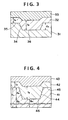
- Fig. 3 is a sectional view schematically illustrating a part of a section of a conventional information recording medium at the prepit area.
- a dye layer 32 made of a dye on a surface of a substrate 31 made of plastic is formed a dye layer 32 made of a dye, and on the dye layer 32 is formed a reflecting layer 33 made of a metal.
- the substrate 31 is provided with a prepit 34.
- the dye layer 32 is a layer prepared by coating a solution for the formation of a dye layer having been prepared by dissolving a dye in a solvent onto the substrate through spin coating and drying the coated layer.
- the thickness t 6 of the dye layer 32 on a bottom portion 36 of the prepit 34 is larger than the thickness t 5 of the dye layer 32 on a portion 35 between the prepits of the substrate 31.
- the depth of a depression (pit-shaped portion) on the interface between the dye layer 32 and the reflecting layer 33 becomes smaller than the depth d 3 of the prepit 34.
- a phase difference between the upper part of the depression (prepit) of the dye layer 32 and the bottom part thereof becomes smaller, whereby the modulation degrees of the prepits become low.
- the dye layer is formed in the same manner as the above on a pregroove area instead of the prepit area, there arises the similar problem. That is, when a recording pit is formed on the pregroove under irradiation with a laser beam to record information, a phase difference between the upper part (corresponding to the land portion of the substrate) of the depression of the dye layer and the bottom part thereof becomes smaller, whereby the modulation degrees of the recording pits become low.
- the depth of the prepit or pregroove is conventionally made large. However, if the depth of the prepit or pregroove, especially pregroove, is made too large, the reflectance of the pregroove portion decreases.
- a dye layer 12 made of a dye on a surface of a substrate 11 made of plastic is formed a dye layer 12 made of a dye, and on the dye layer 12 is formed a reflecting layer 13 made of a metal.
- the substrate 11 is provided with a prepit 14.
- the dye layer 12 is a layer prepared by coating a solution for the formation of a dye layer having a specific property which has been prepared by dissolving a dye in a solvent onto the substrate through spin coating and drying the coated solution. A method for preparation of the above dye solution is hereinafter described.
- Difference between n r ⁇ t 1 and n r ⁇ t 2 is preferably not more than ⁇ /11, more preferably not more than ⁇ /13, most preferably not more than ⁇ /16.
- a dye layer 22 made of a dye on a surface of a substrate 21 made of plastic is formed a dye layer 22 made of a dye, and on the dye layer 12 is formed a reflecting layer 23 made of a metal.
- the substrate 21 is provided with a pregroove 24.
- the dye layer 22 is a layer prepared by coating a solution for the formation of a dye layer having the above specific property on the substrate through spin coating and drying the coated solution.
- Difference between n r ⁇ t 3 and n r ⁇ t 4 is preferably not more than ⁇ /11, more preferably not more than ⁇ /13, most preferably not more than ⁇ /16.
- a ratio of the reflectance of the bottom portion of the pregroove to that of the mirror portion is preferably not less than 70 %, more preferably not less than 80 %, most preferably not less than 90 %.
- the depth d 1 of the pregroove is smaller than the depth of d 2 of the prepit preferably by not less than ⁇ /16, more preferably by not less than ⁇ /14, most preferably by not less than ⁇ /12, in terms of optical path (n-d: n is a refractive index of the substrate and d is a depth thereof).
- the thickness of the dye layer on the land portion and on the portion between the prepits is preferably in the range of 40 to 400 nm, more preferably in the range of 60 to 300 nm, most preferably in the range of 80 to 250 nm.
- the dye layer having specific optical path in the information recording medium (A), that is, a dye layer having such specific optical thickness that difference between the optical thickness of the dye layer on the bottom portion of the pregroove and the optical thickness of the dye layer on the land portion is not more than ⁇ /8, and/or difference between the optical thickness of the dye layer on the bottom portion of the prepit and the optical thickness of the dye layer on the portion between prepits is not more than ⁇ /8, can be prepared by a process for the preparation of the information recording medium of the invention.
- the good solvent and the poor solvent are compatible with each other, and the evaporation speed of the poor solvent is not higher than the evaporation speed of the good solvent at the coating temperature.
- the concentration limit generally becomes larger.
- solvents examples include aromatic hydrocarbon solvents such as benzene, toluene, xylene and ethyl benzene; aliphatic hydrocarbon solvents such as hexane, octane, nonane and cyclohexane; organic acid solvents such as acetic acid; ester solvents such as ethyl acetate, butyl acetate, amyl acetate, and ethylene glycol monoethyl ether acetate (cellosolve acetate); ketone solvents such as acetone, methyl ethyl ketone, methyl isobutyl ketone, diisobutyl ketone and cyclohexanone; halogenated hydrocarbon solvents such as dichloromethane, 1,2-dichloroethane, chloroform, methyl chloroform, trichloroethylene (trichlene), carbon tetrachloride and tetrachloroethylene; hal
- the concentration of the dye in the dye solution is not specifically limited in the process of the invention, provided that the dye solution satisfies the above-mentioned concentration limit.
- the concentration of the dye in the dye solution is generaly 0.5 to 15 wt.%, preferably 1 to 10 wt.%, more preferably 1.5 to 8 wt.%, most preferably 1.5 to 5 wt.%, from the viewpoint of convenience in handling thereof and the formation of a dye layer of uniform thickness on the substrate through spin coating.
- examples of the binders include natural organic polymer materials such as gelatin, dextran, rosin and rubber; and synthetic organic polymer materials such as cellulose derivative (e.g., cellulose acetate and nitrocellulose), hydrocarbon resins (e.g., polyethylene, polypropylene, polystyrene, polyisobutylene and chlorinated polyethylene), vinyl resins (e.g., polyvinyl chloride, polyvinylidene chloride, polyvinyl chloride/polyvinyl acetate copolymer and polyvinyl alcohol), acrylic resins (e.g., polymethyl acrylate and polymethyl methacrylate), and precondensates of thermosetting resins (e.g., epoxy resin, butyral resin, rubber derivative and phenol/formaldehyde resin).
- thermosetting resins e.g., epoxy resin, butyral resin, rubber derivative and phenol/formaldehyde resin
- an enhancing layer may be provided between the dye layer and a reflecting layer which is optionally provided, to enhance the reflectance.
- a reflecting layer is further provided on the dye layer.
- a protective layer may be provided to physically and chemically protect the whole resulting information recording medium, particularly the dye layer and the reflecting layer.
- the protective layer may be also provided on the surface of the substrate where the dye layer is not provided, to improve damage resistance and moisture resistance.
- the protective layer can be formed, for example, by dissolving a thermoplastic resin, a thermosetting resin, etc. to prepare a coating solution, then coating the solution over the reflecting layer, and drying the coated layer of the solution.
- a thermoplastic resin e.g., polymethyl methacrylate
- a thermosetting resin e.g., polymethyl methacrylate
- the resin per se or a solution of the resin in an appropriate solvent is coated over the reflecting layer, and the coated layer is irradiated with ultraviolet rays to cure the layer so as to form a protective layer.
- the information recording medium (B) has a basic structure comprising a substrate provided with a prepit area containing prepits having a specific shape and a pregroove area containing a pregroove, a dye layer and a reflecting layer, superposed in this order and shows a high modulation degree of not less than 50 %.
- the information recording medium (B) preferably a pregroove area containing a pregroove having a specific shape.
- a dye layer 42 made of a dye on a substrate 41 made of plastic is formed a dye layer 42 made of a dye, and on the dye layer 42 is formed a reflecting layer 43 made of a metal.
- the substrate 41 is provided with a prepit 44.
- the dye layer 42 is a layer formed by coating a solution for the formation of a dye layer having been prepared by dissolving a dye in a solvent and drying the coated layer. For the aforementioned reason, the thickness t 8 of the dye layer 42 on a bottom portion 46 of the prepit 44 is larger than the thickness t 7 of the dye layer 42 on the portion 45 between the prepit 44 and its adjoining prepit of the substrate 41.
- the total optical path of an optical path of the substrate 41 and that of the dye layer 42 on the bottom portion 46 of the prepit 44 and the total optical path of an optical path of the substrate 41 and that of the dye layer 42 on the portion 45 between the prepit 44 and its adjoining prepit are each determined as follows.
- the dye having a desired value of n D and the substrate material having a desired value of n B determined as above are not special ones, and they can be selected from those conventionally known. Further, the above-mentioned values t 7 and t 8 are each thickness of a dye layer prepared by coating a dye solution through a conventional coating method. In spite of those conventional materials and known method, difference between OL P1 and OL L1 can be made not less than ⁇ /8 in the information recording medium (B) because the prepit is so formed as to allow its dimension (particularly its depth) to have a value within a specific range.
- difference between OL P1 and OL L1 is not less than ⁇ /8, so that when the medium is irradiated with a laser beam to reproduce information, the phase difference between the portion 45 between prepits and the bottom portion 46 of the prepit becomes large, and thereby reproduced signal having high modulation degree of not less than 50 % can be obtained.
- the substrate material is plastic
- the substrate having the aforementioned prepits and pregroove can be prepared by means of injection molding using a stamper.
- a pregroove layer for forming the prepits and a pregroove may be provided as mentioned above.
- the depth of the pregroove is smaller than the depth of the prepit on the same substrate by not less than ⁇ /8 ( ⁇ has the same meaning as defined above) in terms of optical path.
- the pregroove can be formed simultaneously with the formation of the prepit in the similar manner to that for the prepit.
- Formation of the dye layer can be conducted by dissolving the dye (and a binder, if desired) in a solvent to prepare a coating solution, then coating the solution on the surface of the substrate and drying the coated layer of the solution.
- a ratio of the dye to the binder is generally in the range of 0.01 to 99 % (by weight), preferably 1.0 to 95 % (by weight).
- the thickness of the dye layer on the portion between prepits is preferably in the range of 40 to 400 nm, more preferably 60 to 300 nm, most preferably 80 to 250 nm.
- an enhancing layer may be provided between the dye layer and a reflecting layer which is optionally provided, to enhance the reflectance.
- a reflecting layer is further provided on the dye layer, and a protective layer may be further provided on the dye layer or the reflecting layer.
- Materials and methods for forming the reflecting layer and the protective layer may be the same as those described for the information recording medium (A).
- the information recording medium (C) has a basic structure has a disc-shaped substrate provided with a prepit area containing prepits and a pregroove area containing pregroove, a dye layer containing a dye which is provided on the substrate and a reflecting layer made of a metal which is provided on the dye layer, superposed in this order.
- the medium also shows a high modulation degree of not less than 50 % in a prepit area.
- the relationship between a depth of each of the prepits and a thickness of the dye layer in the prepit area satisfies the following formula (I): 0.15 ⁇ ⁇ n s d p - n d ⁇ t p ⁇ 0.24 ⁇ and the relationship between a depth of the pregroove and a thickness of the dye layer in the pregroove area satisfies the following formula (II): 0.02 ⁇ ⁇ n s d g - n d ⁇ t g ⁇ 0.08 ⁇ in which n s represents a refractive index of the substrate, n d represents a refractive index of the dye layer, d p represents a depth of each of the prepits, ⁇ t p represents a difference between a thickness of the dye layer on the bottom portion of each of the prepits and that of the dye layer on the portion between the prepits, d g represents a depth of the pregroove, ⁇ t g represents a difference
- phase difference of the prepit In the prepit area, intensity of signal generally becomes larger when the reflectance is zero. Such intensity can be obtained when the phase difference of the prepit is 1/4 ⁇ . However, it is required that the phase difference produces push-pill signal for controlling tracking, and further the intensity of such push-pull signal is almost equal to that of the push-pull signal of a pregroove area in the same disc. In the case that the phase difference (corresponding to "n s d p - n d ⁇ t p " in the formula (I)) is within a range defined by the formula (I), both a high modulation degree and an excellent tracking are obtained in the prepit area.
- Fig. 5B is a sectional view schematically illustrating a part of a section of one example of the information recording medium (C) at the pregroove.
- a substrate 51 made of plastic is formed a dye layer 52 made of a dye, and on the dye layer 52 is formed a reflecting layer 53 made of a metal.
- the substrate 51 is provided with a pregroove 57.
- the formula (I) is represented by the following formula (III): 0.17 ⁇ ⁇ n s d p - n d ⁇ t p ⁇ 0.22 ⁇ in which n s , d p , n d , ⁇ t pn and ⁇ are the same as defined above.
- the depth d p of the prepit is preferred in the range of 80 to 300 nm.
- the depth d g of the pregroove is preferred in the range of 10 to 230 nm.
- the difference ⁇ t p of the thickness of the dye layer on the bottom portion of the prepit and that on the portion between prepits is preferred the range of 0 to 120 nm. Further, the difference ⁇ t g of the thickness of the dye layer on the bottom portion of the pregroove and that on the land is preferred the range of 0 to 120 nm.
- the above information recording media (A) to (C) are prepared by coating a dye solution over an almost whole surface of a substrate provided with prepits and a pregroove, and the reproduced signal from the media shows high modulation degrees and high reflectances.
- the information recording medium (D) of the embodiment according to the invention which has a plurality of the prepit areas and pregroove areas in combination.
- the information recording medium (D) has a structure comprising a disc-shaped substrate provided with a prepit area and a pregroove area and a dye layer which is provided on the substrate, the dye layer being a layer for recording information by forming reproducing pits thereon under irradiation with a laser beam, wherein the prepit area has a modulation degree of not less than 50 %, and at least one of the prepit area and the pregroove area is present in two or more places.
- a modulation degree of the prepit area is not less than 50 %, in spite that the dye layer is provided on the substrate having been provided with the prepit area, so that it is possible to form the same dye layer on both the prepit area and the pregroove area of the substrate as mentioned previously.
- the dye layer In an conventional information recording medium having a prepit area and a pregroove area, it is impossible to provide a dye layer on the prepit area as described hereinbefore. Therefore, in order to allow a plurality of prepit area and pregroove area to exist in a mixed state, the dye layer must be formed on only the pregroove area without forming the dye layer on the prepit area. Though the dye layer is generally formed by coating a solution containing a dye over the substrate, formation of the dye layer on only the pregroove area of the substrate is practically difficult.
- the information recording medium (D) of the invention can be prepared by forming a uniform dye layer over the whole surface of the substrate through coating of a dye-containing solution on the substrate having been provided with a prepit area and a pregroove area (at least one of those being present in plural places) using a known coating method.
- a dye-containing solution on the substrate having been provided with a prepit area and a pregroove area (at least one of those being present in plural places) using a known coating method.
- various formats can be formed in the recording medium (D), which is difficult in the conventional recording medium.
- the information area means an area on which information has been previously recorded.
- the area is recorded with information (e.g., program data) by a manufacturer of the recording medium through master-molding, etc.
- the recording area means an area on which a manufacturer or a user of the information recording medium can be additionally record information after the preparation of the medium. On this area, a user can write new data according to the program given by the information area, or a manufacturer of the recording medium can record on each disc (medium) different information such as a user's number.
- One example of utilization of the information area is described below.
- a plurality of programs are recorded on the information area, and permission signal for use of the programs is recorded on the recording area in such a manner that some programs among the plural programs can be used but other programs cannot be used (i.e., protected) for each particular disc.
- permission signal for use of the programs is recorded on the recording area in such a manner that some programs among the plural programs can be used but other programs cannot be used (i.e., protected) for each particular disc.
- several kinds of application discs can be prepared by means of only one process of master-molding.
- the control information area is an area which is sometimes referred to "Read-in", and on this area information for controlling the content of the information area (directory information, time information, number of information such as number of musics, etc.) has been recorded. Otherwise, this area is also an area indicating an information-introducing part in CD-DA (Compact Disc - Digital to Analog).
- the end area which is sometimes referred to "Read-out", indicates the last part of the information area.
- the control area is an area on which various information (e.g., information on forbiddance of copy, information on permission number of copy, information on users to whom copy is permitted, information on user's machine to which copy is permitted and information on the number of copy) has been recorded, or an area on which those information can be recorded.
- the Q area is an area for adjusting a recording or reproducing power and/or an area for temporarily recording information.
- a conventional information recording medium shown in Fig. 11A is provided with one information area composed of a prepit area and one recording area composed of a pregroove area. Between the prepit area and the pregroove area, a gap of about several millimeter is formed. In the conventional information recording medium, a dye layer is formed on only the pregroove area but not formed on the prepit area as described previously, so that the gap is necessarily formed therebetween.
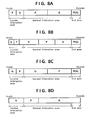
- Figs. 6A to 6E show several embodiments of the structure of the prepit area and the pregroove area in the information recording medium according to the invention.
- the information recording medium shown in Fig. 6A have two prepit areas and two pregroove areas each of which is provided alternately, and each of those areas forms an information area 1, a recording area 1, an information area 2 and a recording area 2, respectively.
- each area can be distributed to a different user, for example, the information area 1 and the recording area 1 are distributed to a user 1 and the information area 2 and the recording area 2 are done to a user 2, whereby a multi-user system can be obtained.
- each area can be distributed to a different program, for example, the information area 1 and the recording area 1 are distributed to a program 1 and the information area 2 and the recording area 2 are done to a program 2, whereby a multi-program system can be obtained.
- the information recording medium (D) of the invention shows such excellent effects that reduction of an access time of a pick-up, and ease of program-controlling and design of system-program are made.
- each prepit area and each pregroove area may be not less than 1 track, and the total size thereof can be enlarged up to the limitation of the capacity of the information recording medium.
- the number of the prepit areas and the pregroove areas can be optionally determined within the range of 3 to 10 7 in a total number. The number depends on the use purpose of the information recording medium and the content of the program.
- Figs. 6A to 6E show embodiments in which any gap is not formed between the prepit area and the pregroove area, but if necessary, a gap of optional size may be formed therebetween.
- a gap of about several millimeter is formed between the prepit area and the pregroove area, as described previously.
- the prepit area no dye layer is formed, and a reflecting layer made of a metal is directly formed on the substrate, so that the prepit area generally has a reflectance of approx. 92 %.
- the pregroove area generally has a reflectance of approx. 84 % because a dye layer is provided thereon.
- an edge part of the dye layer is present, and therefore the reflectance of the gap area is greatly varied within the range of generally approx. 16 to 84 %.
- the pick-up when the pick-up passes through the gap area under focusing, the pick-up sometimes deviates from the focused condition. For coping with this problem, it is required to add a new controlling system to the hardware device. Moreover, the recording capacity of the information recording medium is made smaller because of presence of the gap.
- the information recording medium (D) of the invention even if a gap is intentionally provided depending on the purpose, reflectances of all areas of the medium are substantially the same because a uniform dye layer is formed on all the prepit area, the gap area and the pregroove area, as shown in Fig. 7. Accordingly, in the case of intentionally providing a gap, the pick-up can be kept in the focused condition even when the pick-up is moved under focusing. Naturally, it is possible to provide no gap in the information recording medium of the invention as described above. Accordingly, the information recording medium (D) of the invention can be provided with a gap of optional size, if desired, without any trouble.
- a conventional information recording medium shown in Fig. 11B is provided with a prepit area all over the substrate surface. On the prepit area, a control information area, an information area and an end area are provided. If a recording area is further provided to this recording medium of Fig. 11B, the resulting recording medium is obliged to take a construction of an information recording medium shown in Fig. 11C. In the construction of the information recording medium of Fig. 11C, however, the recording area exists on the outer side of the end area, so that conventional CD players can reproduce information of only the prepit area.
- a pregroove can be formed on an area which is not generally used for reproduction and is present on the inner periphery side and/or the outer periphery side of the ROM area (prepit area) wherein information composed of the prepits has been already recorded, and a control area can be formed on the pregroove, as shown in Figs. 9A to 9C.
- a control area there can be previously recorded information relating to the aforementioned copy using the signal which is not ordinarily employed (for example, RSTUVW code of CD and wobble signal).
- a conventional information recording medium shown in Fig. 11E is provided with a pregroove area all over the substrate surface.
- a control information area, an information area and an end area are provided on the pregroove area.
- the recording procedure must be made for all media using a recording machine, so that a long period of time is required for mass duplication.
- Information recording media may be provided with the aforementioned Q area.
- the resulting information recording medium can take only such a construction as shown in an information recording medium of Fig. 11F or 11G.
- the pick-up is obliged to pass on access the recording area which has been formed by an inadequate recording method in the power-adjusting stage.
- the pass of the pick-up brings about unfavorable influence on the hardware system and the construction does about reduction of the recording region.
- the outer periphery area of the recording medium tends to be easily stained in the handling procedure, and the substrate on the most outer periphery area thereof has a high birefringence so that the formed dye layer tends to be made ununiformly, resulting in severe problems for the power adjustment.
- examples 1 - 12 according to the present invention, particularly to the information recording medium (A) of embodiment thereof and comparison examples 1 - 3 are given below.
- a disc-shaped polycarbonate substrate (outer diameter: 120 mm, inner diameter: 15 mm, thickness: 1.2 mm) provided with prepits (half width of prepit: 0.6 ⁇ m, depth of prepit: 130 nm) having been recorded with EFM signal within the region of from 46 mm to 80 mm in diameter and a pregroove (track pitch: 1.6 ⁇ m, half width of pregroove: 0.55 ⁇ m, depth of pregroove: 50 nm) within the region of from 80 nm to 118 mm in diameter was prepared.
- a dye (I) (refractive index: 2.8) having the following formula was dissolved in propylene glycol monoethyl ether to prepare a dye solution containing 2.4 wt.% of the dye (I).
- the dye solution was kept at 23 °C, and the dye solution was coated over the above-mentioned substrate having a temperature of 23 °C by means of spin coating under the rotation of the substrate at 200 r.p.m. for 4 seconds. Then, the coated layer of the solution on the substrate was dried under the rotation of the substrate at 700 r.p.m. for 30 seconds, to form a dye layer on the substrate.
- a reflecting layer made of Au having a thickness of 100 nm by means of DC sputtering of Au under the conditions of an electric power of 480 W, a target-substrate distance of 95 mm, a gas pressure of 2 Pa and a rate of 2 nm/sec.
- an information recording medium consisting of a substrate, a dye recording layer, a reflecting layer and a protective layer was prepared.
- a dye layer was formed on the substrate in the same manner as described in Example 1 except for using a dye solution having been prepared by dissolving a dye (II) (refractive index: 2.9) having the following formula in a mixture solvent of 2,2,3,3-tetrafluoropropanol and propylene glycol monoethyl ether (ratio by volume: 92 : 8), the dye solution containing the dye (II) in an amount of 2.3 wt.% (the concentration limit of the dye solution at 23 °C was 90 %).
- a dye solution having been prepared by dissolving a dye (II) (refractive index: 2.9) having the following formula in a mixture solvent of 2,2,3,3-tetrafluoropropanol and propylene glycol monoethyl ether (ratio by volume: 92 : 8) the dye solution containing the dye (II) in an amount of 2.3 wt.% (the concentration limit of the dye solution at 23 °C was 90
- the obtained information recording medium was evaluated in the same manner as described in Example 1. The results are set forth in Tables 1A and 1B.
- a dye layer was formed on the substrate in the same manner as described in Example 1 except for using a dye solution having been prepared by dissolving the dye (II) in a mixture solvent of 2,2,3,3-tetrafluoropropanol and butanol (ratio by volume: 70 : 30), the dye solution containing the dye (II) in an amount of 2.3 wt.% (the critical concentration of the dye solution at 23 °C was 90 %). Then, on the dye layer formed on the substrate, a reflecting layer and a protective layer were superposed in order in the same manner as described in Example 1, to prepare an information recording medium.
- the obtained information recording medium was evaluated in the same manner as described in Example 1. The results are set forth in Tables 1A and 1B.
- Example 2 Using the same substrate as used in Example 1 except that the half width of the prepit was 0.5 ⁇ m and the depth of the prepit was 120 nm, a dye layer, a reflecting layer and a protective layer were superposed in order on the substrate in the same manner as described in Example 1. Thus, an information recording medium was prepared.
- the obtained information recording medium was evaluated in the same manner as described in Example 1. The results are set forth in Tables 1A and 1B.
- Example 2 Using the same substrate as used in Example 1 except that the half width of the pre-pit was 0.5 ⁇ m and the depth of the prepit was 90 nm, a dye layer, a reflecting layer and a protective layer were superposed in order on the substrate in the same manner as described in Example 1. Thus, an information recording medium was prepared.
- the obtained information recording medium was evaluated in the same manner as described in Example 1. The results are also set forth in Tables 1A and 1B.
- a dye layer was formed on the substrate in the same manner as described in Example 1 except for using a dye solution having been prepared by dissolving the dye (II) in a mixture solvent of 2,2,3,3-tetrafluoropropanol and isopropyl ether (ratio by volume: 90 : 10), the dye solution containing the dye (II) in an amount of 2.3 wt.% (the concentration limit of the dye solution at 23 °C was 80 %). Then, on the dye layer formed on the substrate, a reflecting layer and a protective layer were superposed in order in the same manner as described in Example 1, to prepare an information recording medium.
- the obtained information recording medium was evaluated in the same manner as described in Example 1. The results are also set forth in Tables 1A and 1B.
- a dye layer was formed on the substrate in the same manner as described in Example 1 except for using a dye solution having been prepared by dissolving the dye (II) in a mixture solvent of 2,2,3,3-tetrafluoropropanol and acetic acid (ratio by volume: 90 : 10), the dye solution containing the dye (II) in an amount of 2.3 wt.% (the concentration limit of the dye solution at 23 °C was 60 %). Then, on the dye layer formed on the substrate, a reflecting layer and a protective layer were superposed in order in the same manner as described in Example 1, to prepare an information recording medium.
- the obtained information recording medium was evaluated in the same manner as described in Example 1. The results are set forth in Tables 1A and 1B.
- a dye layer was formed on the substrate in the same manner as described in Example 1 except for using a dye solution having been prepared by dissolving the dye (II) in a mixture solvent of 2,2,3,3-tetrafluoropropanol and ethyl cellosolve (ratio by volume: 90 : 10), the dye solution containing the dye (II) in an amount of 2.3 wt.% (the concentration limit of the dye solution at 23 °C was 70 %). Then, on the dye layer formed on the substrate, a reflecting layer and a protective layer were superposed in order in the same manner as described in Example 1, to prepare an information recording medium.
- the obtained information recording medium was evaluated in the same manner as described in Example 1. The results are set forth in Tables 1A and 1B.
- a dye layer was formed on the substrate in the same manner as described in Example 1 except for using a dye solution having been prepared by dissolving the dye (II) in a mixture solvent of 2,2,3,3-tetrafluoropropanol and isoamyl alcohol (ratio by volume: 70 : 30), the dye solution containing the dye (II) in an amount of 2.3 wt.% (the concentration limit of the dye solution at 23 °C was 55 %). Then, on the dye layer formed on the substrate, a reflecting layer and a protective layer were superposed in order in the same manner as described in Example 1, to prepare an information recording medium.
- the obtained information recording medium was evaluated in the same manner as described in Example 1. The results are set forth in Tables 1A and 1B.
- a dye layer was formed in the same manner as described in Example 1 except that the dye solution was replaced with the same dye solution as used in Comparison Example 1 except for using a dye solution having been prepared by dissolving the dye (I) in a solvent of 2,2,3,3-tetrafluoropropanol, the dye solution containing the dye (I) in an amount of 2.3 wt.% (the concentration limit of the dye solution at 23°C was less than 20 %). Then, on the dye layer formed on the substrate, a reflecting layer and a protective layer were superposed in order in the same manner as described in Example 1. Thus, an information recording medium was prepared.
- the obtained information recording medium was evaluated in the same manner as described in Example 1. The results are set forth in Tables 1A and 1B.
- a dye layer was formed on the substrate in the same manner as described in Example 1 except for using a dye solution having been prepared by dissolving the dye (II) in 2,2,3,3-tetrafluoropropanol, the dye solution containing the dye (II) in an amount of 2.3 wt.% (the concentration limit of the dye solution at 23°C was less than 20 %). Then, on the dye layer formed on the substrate, a reflecting layer and a protective layer were superposed in order in the same manner as described in Example 1, to prepare an information recording medium.
- the obtained information recording medium was evaluated in the same manner as described in Example 1. The results are set forth in Tables 1A and 1B.
- a dye layer was formed on the substrate in the same manner as described in Example 1 except for using a dye solution having been prepared by dissolving the dye (II) in a mixture solvent of 2,2,3,3-tetrafluoropropanol and ethanol (ratio by volume: 70 : 30), the dye solution containing the dye (II) in an amount of 2.3 wt.% (the concentration limit of the dye solution at 23 °C was less than 20 %). Then, on the dye layer formed on the substrate, a reflecting layer and a protective layer were superposed in order in the same manner as described in Example 1, to prepare an information recording medium.
- the obtained information recording medium was evaluated in the same manner as described in Example 1. The results are set forth in Tables 1A and 1B.
- the information recording medium (A) according to the invention had such excellent properties that both the reflectance of the pregroove and the reflectance thereof after recording of information were high in the pregroove area (information recording area), decrease of the tracking servo gain was small, and the modulation degree in the prepit area (ROM area) was large.
- the reflectance of the pregroove and the reflectance thereof after recording of information were low, decrease of the tracking servo gain was large, and the modulation degree in the prepit area (ROM area) was extremely small.
- a dye (I) having the following formula was dissolved in 2,2,3,3-tetrafluoropropanol to prepare a dye solution containing 2.8 wt.% of the dye (I).
- the dye solution was coated over the above-mentioned substrate at 23 °C by means of spin coating under the rotation of the substrate at 200 r.p.m. for 5 seconds. Then, the coated layer of the solution on the substrate was dried under the rotation of the substrate at 700 r.p.m. for 30 seconds, to form a dye layer on the substrate.
- a reflecting layer made of Au having a thickness of 100 nm by means of DC sputtering of Au under the conditions of an electric power of 480 W, a target-substrate distance of 95 mm, a gas pressure of 2 Pa and a rate of 2 nm/sec.
- a UV-curable resin (trade name: 3070, available from Three Bond Co., Ltd.) by means of spin coating at 1,500 r.p.m., and the coated layer was then irradiated with ultraviolet rays using a high-voltage mercury lamp to cure the coated layer, so as to form a protective layer having a thickness of 2 ⁇ m on the reflecting layer.
- an information recording medium consisting of a substrate, a dye recording layer, a reflecting layer and a protective layer was prepared.
- Example 13 Using the same disc-shaped polycarbonate substrate as that of Example 13 except that the half width of each of prepits having been recorded with EFM signal was 0.65 ⁇ m and the depth of the prepit thereof was 130 nm, instead of the substrate of Example 13, a dye layer, a reflecting layer and a protective layer were superposed in order on the substrate in the same manner as described in Example 13. Thus, an information recording medium was prepared.
- the information recording media of the invention (Examples 15 to 17) have high modulation degree on the prepit area (ROM area) and show excellent characteristics.
- examples 14 - 30 according to the present invention particularly to the information recording media (C) and (D) of embodiments thereof and comparison examples 5 - 7 are given below.
- the dye solution was coated over the above-mentioned substrate by means of spin coating under the rotation of the substrate at 200 r.p.m. for 5 seconds. Then, the coated layer of the solution on the substrate was dried under the rotation of the substrate at 2000 r.p.m. for 30 seconds, to form a dye layer having the thicknesses as described below on the substrate.
- a reflecting layer made of Au having a thickness of 100 nm by means of DC sputtering of Au under the conditions of an electric power of 200 W and a Ar gas pressure of 2 Pa.
- a UV-curable resin (trade name: 3070, available from Three Bond Co., Ltd.) by means of spin coating at 200 r.p.m. and allowed to stand at 1,500 r.p.m. for 30 seconds, and the layer of the resin was irradiated with ultraviolet rays using a high-voltage mercury lamp (200 w/cm) to cure the layer, so as to form a protective layer having a thickness of 2 ⁇ m on the reflecting layer.
- an information recording medium consisting of a substrate, a dye recording layer, a reflecting layer and a protective layer was prepared.
- Example 14 Using the same substrate as used in Example 14 except that the depth of the prepit was 105 nm and the depth of the pregroove was 25 nm, a dye layer having the thicknesses as described below on the substrate, a reflecting layer and a protective layer were superposed in order on the substrate in the same manner as described in Example 14. Thus, an information recording medium was prepared.
- Example 14 Using the same substrate as used in Example 14 except that the depth of the prepit was 90 nm, a dye layer on the substrate, a reflecting layer and a protective layer were superposed in order on the substrate in the same manner as described in Example 14. Thus, an information recording medium was prepared. The resulting dye layer had thicknesses as described below.
- Example 14 Using the same substrate as used in Example 14 except that the depth of the pregroove was 50 nm, a dye layer on the substrate, a reflecting layer and a protective layer were superposed in order on the substrate in the same manner as described in Example 14. Thus, an information recording medium was prepared. The resulting dye layer had thicknesses as described below.
- Example 14 Using the same substrate as used in Example 14 except that the depth of the prepit was 170 nm and the depth of the pregroove was 80 nm, a dye layer on the substrate, a reflecting layer and a protective layer were superposed in order on the substrate in the same manner as described in Example 14. Thus, an information recording medium was prepared. The resulting dye layer had thicknesses as described below.
- Example 14 Using the same substrate as used in Example 14 except that the depth of the prepit was 80 nm and the depth of the pregroove was 50 nm, a dye layer on the substrate, a reflecting layer and a protective layer were superposed in order on the substrate in the same manner as described in Example 14. Thus, an information recording medium was prepared. The resulting dye layer had thicknesses as described below.
- Example 14 Using the same substrate as used in Example 14, a dye layer was formed on the substrate in the same manner as described in Example 14 except for using a dye solution having been prepared by dissolving the dyes (I) and (IV) in a mixture solvent of 2,2,3,3-tetrafluoropropanol 68 ml, ethyl cellosolve 25 ml and tetrachloroethane 7 ml, and then a reflecting layer and a protective layer were superposed in order on the dye layer in the same manner as described in Example 14. Thus, an information recording medium was prepared. The resulting dye layer had thicknesses as described below.
- a dye layer was formed on the substrate in the same manner as described in Example 14 except for using a dye solution having been prepared by dissolving the dyes (I) and (IV) in a single solvent of 2,2,3,3-tetrafluoropropanol 100 ml, and then a reflecting layer and a protective layer were superposed in order on the dye layer in the same manner as described in Example 14.
- a dye solution having been prepared by dissolving the dyes (I) and (IV) in a single solvent of 2,2,3,3-tetrafluoropropanol 100 ml, and then a reflecting layer and a protective layer were superposed in order on the dye layer in the same manner as described in Example 14.
- an information recording medium was prepared.
- the resulting dye layer had thicknesses as described below.
- Example 14 Using the same substrate as used in Example 14, a dye layer was formed on the substrate in the same manner as described in Example 14 except for using a dye solution having been prepared by dissolving the dyes (I) and (IV) in a mixture solvent of 2,2,3,3-tetrafluoropropanol 45 ml, ethyl cellosolve 40 ml and tetrachloroethane 15 ml, and then a reflecting layer and a protective layer were superposed in order on the dye layer in the same manner as described in Example 14. Thus, an information recording medium was prepared. The resulting dye layer had thicknesses as described below.
- a dye layer was formed on the substrate in the same manner as described in Example 14 except for using a dye solution having been prepared by dissolving 2.6 g of a dye (III) as described below and 0.26 g of the dye (IV) in a single solvent of 2,2,3,3-tetrafluoropropanol 100 ml, and then a reflecting layer and a protective layer were superposed in order on the dye layer in the same manner as described in Example 14. Thus, an information recording medium was prepared. The resulting dye layer had thicknesses as described below.
- a dye layer was formed on the substrate in the same manner as described in Example 14 except for using a dye solution having been prepared by dissolving the dyes (I) and (IV) in a mixture solvent of 2,2,3,3-tetrafluoropropanol 75 ml, propylene glycol monomethyl ether 20 ml and tetrachloroethane 5 ml, and then a reflecting layer and a protective layer were superposed in order on the dye layer in the same manner as described in Example 14.
- a dye solution having been prepared by dissolving the dyes (I) and (IV) in a mixture solvent of 2,2,3,3-tetrafluoropropanol 75 ml, propylene glycol monomethyl ether 20 ml and tetrachloroethane 5 ml, and then a reflecting layer and a protective layer were superposed in order on the dye layer in the same manner as described in Example 14.
- an information recording medium was prepared.
- the resulting dye layer had thicknesses as
- a dye layer was formed on the substrate in the same manner as described in Example 14 except for using a dye solution having been prepared by dissolving the dyes (I) and (IV) in a mixture solvent of 2,2,3,3-tetrafluoropropanol 75 ml, diisobutyl ketone 20 ml and tetrachloroethane 5 ml, and then a reflecting layer and a protective layer were superposed in order on the dye layer in the same manner as described in Example 14.
- a dye solution having been prepared by dissolving the dyes (I) and (IV) in a mixture solvent of 2,2,3,3-tetrafluoropropanol 75 ml, diisobutyl ketone 20 ml and tetrachloroethane 5 ml, and then a reflecting layer and a protective layer were superposed in order on the dye layer in the same manner as described in Example 14.
- an information recording medium was prepared.
- the resulting dye layer had thicknesses as
- Example 14 Using the same substrate as used in Example 14, a dye layer was formed on the substrate in the same manner as described in Example 14 except for using a dye solution having been prepared by dissolving the dyes (I) and (IV) in a mixture solvent of 2,2,3,3-tetrafluoropropanol 75 ml, ethylcaprilate 20 ml and tetrachloroethane 5 ml, and then a reflecting layer and a protective layer were superposed in order on the dye layer in the same manner as described in Example 14. Thus, an information recording medium was prepared. The resulting dye layer had thicknesses as described below.
- Example 14 Using the same substrate as used in Example 14, a dye layer was formed on the substrate in the same manner as described in Example 14 except for using a dye solution having been prepared by dissolving the dyes (I) and (IV) in a mixture solvent of 2,2,3,3-tetrafluoropropanol 75 ml, 1-pentanol 20 ml and tetrachloroethane 5 ml, and then a reflecting layer and a protective layer were superposed in order on the dye layer in the same manner as described in Example 14. Thus, an information recording medium was prepared. The resulting dye layer had thicknesses as described below.
- Example 14 Using the same substrate as used in Example 14, a dye layer was formed on the substrate in the same manner as described in Example 14 except for using a dye solution having been prepared by dissolving 3.25 g of the dye (II) and 0.325 g of the dye (IV) in a mixture solvent of 2,2,3,3-tetrafluoropropanol 82 ml, ethyl cellosolve 13 ml and tetrachloroethane 5 ml, and then a reflecting layer and a protective layer were superposed in order on the dye layer in the same manner as described in Example 14. Thus, an information recording medium was prepared. The resulting dye layer had thicknesses as described below.
- CD format signal was recorded on the bottom portion of the pregroove in the outside region from 72 mm in diameter of the information recording medium obtained in the above using a disc-evaluation device (DDU1000, available from Pulsteck Co., Ltd. : NA: 0.5, laser wavelength: 780 nm) under the conditions of a laser power for recording signal (recording power) of 7.4 mW and a fixed linear speed of 1.4 m/sec.
- DDU1000 disc-evaluation device
- Table 3A Dye Solvent (ml) d p d g ⁇ t p ⁇ t g Kind Amount(g) a b c d e f g (nm) (nm) Ex. 14 I/IV 3.25/0.325 75 20 5 110 37 5 5 Ex. 15 I/IV 3.25/0.325 75 20 5 105 25 5 5 Ex. 16 I/IV 3.25/0.325 75 20 5 115 40 5 5 Ex. 17 I/IV 3.25/0.325 75 20 5 90 37 5 5 Ex.
- a disc-shaped polycarbonate substrate (outer diameter: 120 mm, inner diameter: 15 mm, thickness: 1.2 mm) having a prepit area (half width: 0.6 ⁇ m, depth: 120 nm) having been recorded with EFM signal within the region of from 46 mm to 70 mm in diameter and within the region of from 116 mm to 118 mm in diameter, and having a pregroove area (half width: 0.45 ⁇ m, depth: 45 nm) within the region of from 42 mm to 46 mm in diameter and within region of from 70 mm to 116 mm in diameter was prepared.
- the dye solution was kept at 23 °C, and the dye solution was coated over the above-mentioned substrate having a temperature of 23 °C by means of spin coating under the rotation of the substrate at 200 r.p.m. for 4 seconds. Then, the coated layer of the solution on the substrate was dried under the rotation of the substrate at 700 r.p.m. for 30 seconds, to form a dye layer on the substrate.
- the optical film-thickness of the dye layer on the bottom portion of the prepit was 360 nm, and the optical thickness thereof on the portion between prepits was 320 nm.
- a reflecting layer made of Au having a thickness of 100 nm by means of DC sputtering of Au under the conditions of an electric power of 480 W, a target-substrate distance of 95 mm, a gas pressure of 2 Pa and a rate of 2 nm/sec.
- UV-curable resin (trade name: 3070, available from Three Bond Co., Ltd.) by means of spin coating at 1,500 r.p.m., to form a protective layer having a thickness of 2 ⁇ m on the reflecting layer.
- an information recording medium consisting of a substrate, a dye recording layer, a reflecting layer and a protective layer was prepared.
- the obtained information recording medium was evaluated by the following evaluation methods. As a result, the modulation degree of the prepit area was 68 %, the reflectance of the prepit area was 84 %, and the modulation degree of the pregroove area was 64 %.
- signal existing all over the area of the information recording medium was capable of being reproduced by commercially available reproducing machines such as a CD-ROM player.
- Example 30 The procedures of Example 30 were repeated except for using the same disc-shaped polycarbonate substrate as that of Example 34 except that the prepit area was formed within the region of from 46 mm to 70 mm in diameter and the pregroove are was formed within the region of from 70 to 116 mm in diameter, to prepare an information recording medium.
- a modulation degree of the prepit area, a reflectance of the prepit area and a modulation degree of the pregroove area were the same as those of the information recording medium obtained in Example 30.
- a modulation degree of the prepit area, a reflectance of the prepit area and a modulation degree of the pregroove area were the same as those of the information recording medium obtained in Example 30.
- Example 30 The procedures of Example 30 were repeated except for using the same disc-shaped polycarbonate substrate as that of Example 30 except that the prepit area was formed within the region of from 46 mm to 118 mm in diameter and the pregroove area was formed within the region of from 44 to 46 mm in diameter, to prepare an information recording medium (a).
- Example 30 Further, the procedures of Example 30 were repeated except for using the same disc-shaped polycarbonate substrate as that of Example 30 except that the pregroove area was formed within the region of from 46 to 118 mm in diameter, to prepare an information recording medium (b).
- a modulation degree of the prepit area, a reflectance of the prepit area and a modulation degree of the pregroove portion were the same as those of the information recording medium obtained in Example 30.
- signal existing all over the area of the information recording medium was capable of being reproduced by commercially available reproducing machines such as a CD-ROM player.
- the information recorded on the prepit area of the information recording medium (a) was copied onto the pregroove area of the information recording medium (b) using a reproducing and copying machine capable of copying from digital to digital.
- a system was incorporated into the machine such a manner that the information was able to be copied by means of a digital-to-digital copy.
- the medium was designed such a manner that signal of 3T were recorded on the area of 45 mm in diameter, and then copy of information was started. As a result, any other copy from the information recording medium (a) was impossible.
Landscapes
- Engineering & Computer Science (AREA)
- Manufacturing & Machinery (AREA)
- Optical Record Carriers And Manufacture Thereof (AREA)
- Optical Recording Or Reproduction (AREA)
Claims (11)
- Support d'enregistrement d'information comprenant un substrat (11) en forme de disque muni de précuvettes (34) contenues dans une zone de précuvettes (P) et d'un présillon (24) contenu dans une zone de présillon (G), la zone de précuvettes contenant une information enregistrée auparavant, la zone de présillon étant une zone enregistrable, la zone de précuvettes et la zone de présillon étant séparées en direction radiale, une couche de colorant (32) qui est prévue sur le substrat dans la zone de présillon, ladite couche de colorant étant une couche pour enregistrer une information dans ladite zone de pré-sillon par formation sur celle-ci de cuvettes reproductibles par irradiation avec un faisceau laser, et une couche réfléchissante (33) constituée par un métal qui est prévue sur la couche de colorant, caractérisé en ce que la couche de colorant est une couche continue formée sur la zone de précuvettes et sur la zone de présillon, et la zone de précuvettes a un degré de modulation qui n'est pas inférieur à 50 %.
- Support d'enregistrement d'information selon la revendication 1, dans lequel la différence entre l'épaisseur optique de la couche de colorant sur la partie de fond de chacune des précuvettes et celle de la couche de colorant sur la partie entre les précuvettes adjacentes n'est pas supérieure à λ/8, λ étant une longueur d'onde d'un faisceau laser de reproduction.
- Support d'enregistrement d'information selon la revendication 1, dans lequel chacune des précuvettes a une demi-largeur de 0,2 à 1,4 µm et une profondeur de 150 à 400 nm, et le trajet optique total d'un trajet optique dudit substrat et de celui de la couche de colorant sur la partie de fond de chacune des précuvettes est plus long d'au moins λ/8 que le trajet optique total d'un trajet optique du substrat et de celui de la couche de colorant sur la partie entre les précuvettes adjacentes, λ étant une longueur d'onde d'un faisceau laser de reproduction.
- Support d'enregistrement d'information selon la revendication 1, dans lequel la différence entre l'épaisseur optique de la couche de colorant sur la partie de fond du présillon et celle de la couche de colorant sur une partie crête de celle-ci n'est pas supérieure à λ/8, λ étant une longueur d'onde d'un faisceau laser de reproduction.
- Support d'enregistrement d'information selon la revendication 1, dans lequel chacune des précuvettes a une demi-largeur de 0,2 à 1,4 µm et une profondeur de 150 à 400 nm, le présillon a une demi-largeur de 0,2 à 1,4 µm et une profondeur de 70 à 200 nm, la profondeur de chacune des précuvettes est supérieure d'au moins λ/8 (λ est une longueur d'onde d'un faisceau laser de reproduction) à la profondeur du présillon en termes de trajet optique, et le trajet optique total d'un trajet optique du substrat et de celui de la couche de colorant sur la partie de fond de chacune des précuvettes est plus long d'au moins λ/8 (λ est tel que défini ci-dessus) que le trajet optique total d'un trajet optique du substrat et de celui de la couche de colorant sur la partie entre les précuvettes adjacentes.
- Support d'enregistrement d'information selon la revendication 1, dans lequel la zone de précuvettes est divisée en deux zones qui sont disposées des deux côtés de la zone de présillon.
- Support d'enregistrement d'information selon la revendication 1, dans lequel la zone de présillon est divisée en deux zones qui sont disposées des deux côtés de la zone de précuvettes.
- Support d'enregistrement d'information selon la revendication 1, dans lequel la zone de précuvettes et la zone de présillon sont divisées l'une et l'autre en deux zones supplémentaires, respectivement, et les zones de précuvettes et les zones de présillon divisées sont disposées côte à côte.
- Support d'enregistrement d'information selon la revendication 1, dans lequel la relation entre la profondeur de chacune des précuvettes et l'épaisseur de la couche de colorant dans la zone de précuvettes obéit à la formule (I) suivante :


- Procédé de préparation d'un support d'enregistrement d'information comprenant les étapes de :revêtement d'un substrat muni de précuvettes contenues dans une zone de précuvettes et d'un présillon contenu dans une zone de présillon, la zone de précuvettes contenant une information enregistrée auparavant, la zone de présillon et la zone de précuvettes étant séparées en direction radiale, avec une solution de colorant ayant une limite de concentration de 99 à 20 % préparée par dissolution d'un colorant dans un solvant, par revêtement centrifuge, la limite de concentration étant définie comme le rapport d'un volume d'une suspension de colorant, lorsque le colorant de la solution de colorant commence à précipiter par évaporation du solvant de la solution de colorant à la température de revêtement, à un volume initial de la solution de colorant,séchage de la couche appliquée en revêtement pour former une couche de colorant dans laquelle la différence entre l'épaisseur optique de la couche de colorant sur la partie de fond de la précuvette et celle de la couche de colorant sur la zone entre les précuvettes adjacentes lorsque le substrat est muni des précuvettes n'est pas supérieure à λ/8, λ étant une longueur d'onde d'un faisceau laser de reproduction, ladite couche de colorant étant une couche pour enregistrer une information dans la zone de présillon par formation sur celle-ci de cuvettes reproductibles par irradiation avec un faisceau laser, puisformation d'une couche réfléchissante constituée par un métal sur la couche de colorant.
- Procédé de préparation d'un support d'enregistrement d'information selon la revendication 8, dans lequel la couche de colorant est formée d'une manière telle que la différence entre l'épaisseur optique de la couche de colorant sur la partie de fond du présillon et celle de la couche de colorant sur la partie crête n'est pas supérieure à λ/8, λ étant une longueur d'onde d'un faisceau laser de reproduction.
Applications Claiming Priority (6)
| Application Number | Priority Date | Filing Date | Title |
|---|---|---|---|
| JP191257/90 | 1990-07-19 | ||
| JP2191257A JP2957651B2 (ja) | 1990-07-19 | 1990-07-19 | 情報記録媒体及びその製造方法 |
| JP2267865A JP2966077B2 (ja) | 1990-10-05 | 1990-10-05 | 情報記録媒体 |
| JP26786490A JP3152351B2 (ja) | 1990-10-05 | 1990-10-05 | 情報記録媒体 |
| JP267865/90 | 1990-10-05 | ||
| JP267864/90 | 1990-10-05 |
Publications (3)
| Publication Number | Publication Date |
|---|---|
| EP0467716A2 EP0467716A2 (fr) | 1992-01-22 |
| EP0467716A3 EP0467716A3 (en) | 1992-09-23 |
| EP0467716B1 true EP0467716B1 (fr) | 1996-10-30 |
Family
ID=27326456
Family Applications (1)
| Application Number | Title | Priority Date | Filing Date |
|---|---|---|---|
| EP91306621A Expired - Lifetime EP0467716B1 (fr) | 1990-07-19 | 1991-07-19 | Milieu d'enregistrement d'information et son procédé de préparation |
Country Status (3)
| Country | Link |
|---|---|
| US (1) | US5274623A (fr) |
| EP (1) | EP0467716B1 (fr) |
| DE (1) | DE69122916T2 (fr) |
Families Citing this family (55)
| Publication number | Priority date | Publication date | Assignee | Title |
|---|---|---|---|---|
| CA2065653A1 (fr) * | 1991-04-16 | 1992-10-17 | Tadashi Koike | Support d'enregistrement optique |
| JPH0540964A (ja) * | 1991-08-06 | 1993-02-19 | Canon Inc | 光学的記録媒体 |
| JPH05303769A (ja) * | 1992-04-27 | 1993-11-16 | Sharp Corp | 光ディスク |
| JP3170062B2 (ja) * | 1992-09-25 | 2001-05-28 | パイオニア株式会社 | 光ディスク |
| JP2879185B2 (ja) * | 1993-04-16 | 1999-04-05 | ティーディーケイ株式会社 | 光磁気ディスク |
| JP2853724B2 (ja) * | 1993-06-30 | 1999-02-03 | 日本ビクター株式会社 | 光記録媒体、その製造方法及びその再生装置 |
| US6487163B1 (en) * | 1994-01-19 | 2002-11-26 | Kabushiki Kaisha Toshiba | Optical disk and optical disk apparatus |
| US5602825A (en) * | 1994-01-19 | 1997-02-11 | Kabushiki Kaisha Toshiba | Optical disk and optical disk apparatus |
| USRE38643E1 (en) | 1994-01-19 | 2004-11-02 | Kabushiki Kaisha Toshiba | Optical disk having specified track pitch, and optical disk apparatus |
| EP0664541B1 (fr) * | 1994-01-19 | 2000-03-29 | Kabushiki Kaisha Toshiba | Système comprenant un disque optique et un appareil pour disque optique |
| US5959963A (en) * | 1994-01-19 | 1999-09-28 | Kabushiki Kaisha Toshiba | Optical disk and optical disk apparatus |
| IL112759A0 (en) * | 1994-02-25 | 1995-05-26 | Khepri Pharmaceuticals Inc | Novel cysteine protease inhibitors |
| JP3284744B2 (ja) * | 1994-04-20 | 2002-05-20 | 松下電器産業株式会社 | 光学的情報記録媒体 |
| KR100285541B1 (en) * | 1994-09-30 | 2001-01-04 | Samsung Electronics Co Ltd | Method for manufacturing organic optical cd-recordable disc |
| EP0736865A1 (fr) * | 1995-04-06 | 1996-10-09 | Eastman Kodak Company | Solution décolorant avec un solvant à empêchement stérique |
| JP2955224B2 (ja) * | 1995-12-28 | 1999-10-04 | 花王株式会社 | 光ディスク用基板の製造方法 |
| US5959960A (en) * | 1996-09-27 | 1999-09-28 | Eastman Kodak Company | Method of providing a range of conformalities for optical recording layers |
| JP3255051B2 (ja) * | 1996-12-05 | 2002-02-12 | 三菱化学株式会社 | 光学的情報記録用媒体 |
| US6070799A (en) * | 1997-01-08 | 2000-06-06 | Eastman Kodak Company | Copy protection for a recordable medium and for controlling a recorder |
| US5963536A (en) * | 1997-04-08 | 1999-10-05 | Eastman Kodak Company | Copy count protection structure for optical recording medium and method for same |
| US5972459A (en) * | 1997-04-25 | 1999-10-26 | Sony Corporation | Optical recording medium and optical disk apparatus |
| US6167136A (en) * | 1997-05-16 | 2000-12-26 | Software Security, Inc. | Method for preventing copying of digital video disks |
| JP3336524B2 (ja) * | 1997-08-01 | 2002-10-21 | 太陽誘電株式会社 | 光情報記録媒体 |
| JP3097628B2 (ja) * | 1997-11-11 | 2000-10-10 | 富士電機株式会社 | 光記録媒体 |
| JP3286249B2 (ja) * | 1998-05-27 | 2002-05-27 | ティーディーケイ株式会社 | 光記録媒体の製造方法 |
| JP3520203B2 (ja) * | 1998-07-23 | 2004-04-19 | 太陽誘電株式会社 | 光情報媒体 |
| MY130565A (en) | 1998-09-18 | 2007-06-29 | Samsung Electronics Co Ltd | Near-field optical storage medium and optical data storage system therefor |
| JP2000298888A (ja) * | 1999-04-15 | 2000-10-24 | Canon Inc | 光磁気記録媒体 |
| TW490666B (en) | 1999-04-22 | 2002-06-11 | Tdk Corp | Method of manufacturing a photo-recording medium and said photo-recording medium |
| US7016295B2 (en) * | 2000-04-26 | 2006-03-21 | Optical Disc Corporation | Hybrid discs displaying certain dimensional values |
| CN1326126C (zh) | 2000-05-17 | 2007-07-11 | 日本胜利株式会社 | 信息记录媒体及其记录方法 |
| WO2002037486A1 (fr) * | 2000-10-23 | 2002-05-10 | Mitsui Chemicals, Inc. | Support d"enregistrement optique |
| JP2002150557A (ja) * | 2000-11-10 | 2002-05-24 | Pioneer Electronic Corp | 光学式記録媒体の記録装置及び方法 |
| US6733957B2 (en) * | 2000-12-27 | 2004-05-11 | Victor Company Of Japan | Disk substrate and manufacturing method therefor, and disk manufactured by the disk substrate |
| JP2003006875A (ja) * | 2001-06-22 | 2003-01-10 | Sony Corp | 光記録媒体 |
| TW200300930A (en) * | 2001-11-20 | 2003-06-16 | Interaxia Ag | Optical storage medium being recordable once, stamper for producing the storage medium and method for producing the stamper |
| US7221642B2 (en) * | 2002-01-18 | 2007-05-22 | Koninklijke Philips Electronics N. V. | Optical data storage medium and use of such medium |
| AU2003226324A1 (en) * | 2002-04-10 | 2003-10-27 | Verification Technologies, Inc. | Content replication deterrent method on optical discs |
| JP4273705B2 (ja) * | 2002-05-13 | 2009-06-03 | 日本電気株式会社 | 光ディスク媒体 |
| EP1548082B1 (fr) * | 2002-08-30 | 2007-08-08 | Asahi Glass Company, Limited | Composition adhesive et plaque en verre avec un moulage elastomere thermoplastique |
| JP4105165B2 (ja) * | 2002-12-13 | 2008-06-25 | 富士通株式会社 | 光磁気記録媒体及び光磁気記憶装置 |
| US7700258B2 (en) * | 2003-01-24 | 2010-04-20 | Hewlett-Packard Development Company, L.P. | Color forming compositions with improved marking sensitivity and image contrast and associated methods |
| JP2004241023A (ja) * | 2003-02-04 | 2004-08-26 | Fuji Photo Film Co Ltd | 磁気転写用マスター担体 |
| KR101049985B1 (ko) * | 2003-08-07 | 2011-07-19 | 파나소닉 주식회사 | 광학적 정보 기록 매체와 그 제조 방법, 제조 장치, 기록재생 방법 및 기록 재생 장치 |
| US7329630B2 (en) | 2003-09-05 | 2008-02-12 | Hewlett-Packard Development Company, L.P. | Stabilizers and anti-fade agents for use in infrared sensitive leuco dye compositions |
| JP2005122774A (ja) * | 2003-10-14 | 2005-05-12 | Nec Corp | 記録型光ディスク装置および光ディスク媒体 |
| JP2005129108A (ja) * | 2003-10-22 | 2005-05-19 | Fuji Photo Film Co Ltd | 光情報記録媒体 |
| JP2005141809A (ja) * | 2003-11-05 | 2005-06-02 | Fuji Photo Film Co Ltd | 光記録媒体および情報記録方法 |
| JP2005190616A (ja) * | 2003-12-26 | 2005-07-14 | Taiyo Yuden Co Ltd | 光情報記録媒体 |
| JP2006040446A (ja) * | 2004-07-28 | 2006-02-09 | Toshiba Corp | 光ディスク及び情報再生装置 |
| JP4168423B2 (ja) * | 2004-07-30 | 2008-10-22 | 太陽誘電株式会社 | 光情報記録媒体 |
| JP2006236416A (ja) * | 2005-02-22 | 2006-09-07 | Toshiba Corp | 記憶媒体、再生方法及び記録方法 |
| US20090129231A1 (en) * | 2005-08-31 | 2009-05-21 | Fujifilm Corporation | Method of manufacturing optical disc, stamper, signal processing method, signal processing apparatus, image drawing method ,Optical disc recording apparatus, and optical recording medium |
| EP1788565A1 (fr) * | 2005-11-16 | 2007-05-23 | Thomson Licensing S.A. | Procédé de lecture et d'enregistrement optiques rapides |
| JP2008010125A (ja) * | 2006-06-30 | 2008-01-17 | Toshiba Corp | 情報記録媒体、及びディスク装置 |
Family Cites Families (16)
| Publication number | Priority date | Publication date | Assignee | Title |
|---|---|---|---|---|
| US4519064A (en) * | 1980-10-27 | 1985-05-21 | Nippon Columbia Kabushikikaisha | Optical record disc |
| NL8301632A (nl) * | 1983-05-09 | 1984-12-03 | Philips Nv | Registratiedrager waarin langs optische weg informatie kan worden ingeschreven en uitgelezen. |
| EP0143992A1 (fr) * | 1983-11-02 | 1985-06-12 | Ricoh Company, Ltd | Milieu d'enregistrement optique d'information |
| US5144552A (en) * | 1986-07-25 | 1992-09-01 | Ricoh Company, Ltd. | Optical information storage medium having grooves and pits with specific depths, respectively |
| US4860273A (en) * | 1986-07-31 | 1989-08-22 | Fuji Photo Film Co., Ltd. | Method of recording information and information recording medium employed for the same |
| JP2671139B2 (ja) * | 1987-12-10 | 1997-10-29 | 富士写真フイルム株式会社 | 情報記録媒体,光情報記録方法および光情報記録再生方法 |
| US5090009A (en) * | 1988-07-30 | 1992-02-18 | Taiyo Yuden Co., Ltd. | Optical information recording medium |
| US4940618A (en) * | 1988-07-30 | 1990-07-10 | Taiyo Yuden Company, Ltd. | Optical information recording medium |
| DE68921453T2 (de) * | 1988-12-28 | 1995-07-13 | Canon Kk | Informationsaufzeichnungsträger. |
| DE69033550T2 (de) * | 1989-03-03 | 2001-01-18 | Tdk Corp., Tokio/Tokyo | Medium für optische Datenspeicherung |
| US5075147A (en) * | 1989-03-24 | 1991-12-24 | Fuji Photo Film Co., Ltd. | Method for optically recording information and information recorded medium |
| EP0404521A3 (fr) * | 1989-06-21 | 1991-05-02 | Hitachi Maxell Ltd. | Support d'enregistrement optique et sa méthode de fabrication |
| MY105953A (en) * | 1989-07-24 | 1995-02-28 | Taiyo Yuden Kk | Optical information recording medium and recording method. |
| NL9002024A (nl) * | 1990-09-14 | 1992-04-01 | Philips Nv | Optisch registratie-element. |
| US5213859A (en) * | 1990-12-21 | 1993-05-25 | Tdk Corporation | Optical recording disk |
| JPH0547044A (ja) * | 1991-08-13 | 1993-02-26 | Pioneer Electron Corp | 追記型光デイスク |
-
1991
- 1991-07-18 US US07/732,186 patent/US5274623A/en not_active Expired - Lifetime
- 1991-07-19 EP EP91306621A patent/EP0467716B1/fr not_active Expired - Lifetime
- 1991-07-19 DE DE69122916T patent/DE69122916T2/de not_active Expired - Fee Related
Also Published As
| Publication number | Publication date |
|---|---|
| DE69122916D1 (de) | 1996-12-05 |
| DE69122916T2 (de) | 1997-03-13 |
| EP0467716A3 (en) | 1992-09-23 |
| US5274623A (en) | 1993-12-28 |
| EP0467716A2 (fr) | 1992-01-22 |
Similar Documents
| Publication | Publication Date | Title |
|---|---|---|
| EP0467716B1 (fr) | Milieu d'enregistrement d'information et son procédé de préparation | |
| US5075147A (en) | Method for optically recording information and information recorded medium | |
| US5244774A (en) | Optical information recording medium | |
| JP2686841B2 (ja) | 情報記録媒体及び光情報記録方法 | |
| JP2966077B2 (ja) | 情報記録媒体 | |
| JP2514846B2 (ja) | 光情報記録方法及び情報記録媒体 | |
| JP2668604B2 (ja) | 光情報記録方法 | |
| JP2957651B2 (ja) | 情報記録媒体及びその製造方法 | |
| JP3152351B2 (ja) | 情報記録媒体 | |
| JP2652279B2 (ja) | 情報記録媒体 | |
| JP2529133B2 (ja) | 情報記録媒体 | |
| JP3087902B2 (ja) | 情報記録媒体及びその製造方法 | |
| JP2794643B2 (ja) | 情報記録媒体 | |
| JP2529131B2 (ja) | 情報記録媒体 | |
| JP2747744B2 (ja) | 光情報記録方法 | |
| JP2530515B2 (ja) | 情報記録媒体及びその製造方法 | |
| JPH0322224A (ja) | 光情報記録方法および情報記録媒体 | |
| JP2604273B2 (ja) | 光情報記録方法 | |
| JP3011969B2 (ja) | 情報記録媒体 | |
| JPH04335223A (ja) | 情報記録媒体 | |
| JP2811360B2 (ja) | 情報記録媒体 | |
| JP3141998B2 (ja) | 情報記録媒体 | |
| JP3651709B2 (ja) | 光記録媒体及びその製造方法 | |
| JP3184200B2 (ja) | 情報記録媒体 | |
| JP3292904B2 (ja) | 光記録媒体 |
Legal Events
| Date | Code | Title | Description |
|---|---|---|---|
| PUAI | Public reference made under article 153(3) epc to a published international application that has entered the european phase |
Free format text: ORIGINAL CODE: 0009012 |
|
| AK | Designated contracting states |
Kind code of ref document: A2 Designated state(s): DE FR GB |
|
| PUAL | Search report despatched |
Free format text: ORIGINAL CODE: 0009013 |
|
| AK | Designated contracting states |
Kind code of ref document: A3 Designated state(s): DE FR GB |
|
| 17P | Request for examination filed |
Effective date: 19930315 |
|
| GRAG | Despatch of communication of intention to grant |
Free format text: ORIGINAL CODE: EPIDOS AGRA |
|
| 17Q | First examination report despatched |
Effective date: 19951212 |
|
| GRAH | Despatch of communication of intention to grant a patent |
Free format text: ORIGINAL CODE: EPIDOS IGRA |
|
| GRAH | Despatch of communication of intention to grant a patent |
Free format text: ORIGINAL CODE: EPIDOS IGRA |
|
| GRAA | (expected) grant |
Free format text: ORIGINAL CODE: 0009210 |
|
| AK | Designated contracting states |
Kind code of ref document: B1 Designated state(s): DE FR GB |
|
| REF | Corresponds to: |
Ref document number: 69122916 Country of ref document: DE Date of ref document: 19961205 |
|
| ET | Fr: translation filed | ||
| PLBE | No opposition filed within time limit |
Free format text: ORIGINAL CODE: 0009261 |
|
| STAA | Information on the status of an ep patent application or granted ep patent |
Free format text: STATUS: NO OPPOSITION FILED WITHIN TIME LIMIT |
|
| 26N | No opposition filed | ||
| REG | Reference to a national code |
Ref country code: GB Ref legal event code: IF02 |
|
| REG | Reference to a national code |
Ref country code: GB Ref legal event code: 732E |
|
| REG | Reference to a national code |
Ref country code: FR Ref legal event code: CD Ref country code: FR Ref legal event code: TP |
|
| PGFP | Annual fee paid to national office [announced via postgrant information from national office to epo] |
Ref country code: DE Payment date: 20080724 Year of fee payment: 18 |
|
| PGFP | Annual fee paid to national office [announced via postgrant information from national office to epo] |
Ref country code: FR Payment date: 20080718 Year of fee payment: 18 |
|
| PGFP | Annual fee paid to national office [announced via postgrant information from national office to epo] |
Ref country code: GB Payment date: 20080723 Year of fee payment: 18 |
|
| GBPC | Gb: european patent ceased through non-payment of renewal fee |
Effective date: 20090719 |
|
| REG | Reference to a national code |
Ref country code: FR Ref legal event code: ST Effective date: 20100331 |
|
| PG25 | Lapsed in a contracting state [announced via postgrant information from national office to epo] |
Ref country code: FR Free format text: LAPSE BECAUSE OF NON-PAYMENT OF DUE FEES Effective date: 20090731 |
|
| PG25 | Lapsed in a contracting state [announced via postgrant information from national office to epo] |
Ref country code: GB Free format text: LAPSE BECAUSE OF NON-PAYMENT OF DUE FEES Effective date: 20090719 |
|
| PG25 | Lapsed in a contracting state [announced via postgrant information from national office to epo] |
Ref country code: DE Free format text: LAPSE BECAUSE OF NON-PAYMENT OF DUE FEES Effective date: 20100202 |