EP0467853A1 - Dispositif et procédé destinés à la mesure de la pression sanguine - Google Patents
Dispositif et procédé destinés à la mesure de la pression sanguine Download PDFInfo
- Publication number
- EP0467853A1 EP0467853A1 EP91810569A EP91810569A EP0467853A1 EP 0467853 A1 EP0467853 A1 EP 0467853A1 EP 91810569 A EP91810569 A EP 91810569A EP 91810569 A EP91810569 A EP 91810569A EP 0467853 A1 EP0467853 A1 EP 0467853A1
- Authority
- EP
- European Patent Office
- Prior art keywords
- blood pressure
- blood
- measure
- pulse wave
- variable
- Prior art date
- Legal status (The legal status is an assumption and is not a legal conclusion. Google has not performed a legal analysis and makes no representation as to the accuracy of the status listed.)
- Granted
Links
Images


Classifications
-
- A—HUMAN NECESSITIES
- A61—MEDICAL OR VETERINARY SCIENCE; HYGIENE
- A61B—DIAGNOSIS; SURGERY; IDENTIFICATION
- A61B5/00—Measuring for diagnostic purposes; Identification of persons
- A61B5/02—Detecting, measuring or recording for evaluating the cardiovascular system, e.g. pulse, heart rate, blood pressure or blood flow
- A61B5/021—Measuring pressure in heart or blood vessels
- A61B5/02108—Measuring pressure in heart or blood vessels from analysis of pulse wave characteristics
- A61B5/02125—Measuring pressure in heart or blood vessels from analysis of pulse wave characteristics of pulse wave propagation time
-
- A—HUMAN NECESSITIES
- A61—MEDICAL OR VETERINARY SCIENCE; HYGIENE
- A61B—DIAGNOSIS; SURGERY; IDENTIFICATION
- A61B5/00—Measuring for diagnostic purposes; Identification of persons
- A61B5/02—Detecting, measuring or recording for evaluating the cardiovascular system, e.g. pulse, heart rate, blood pressure or blood flow
- A61B5/021—Measuring pressure in heart or blood vessels
-
- A—HUMAN NECESSITIES
- A61—MEDICAL OR VETERINARY SCIENCE; HYGIENE
- A61B—DIAGNOSIS; SURGERY; IDENTIFICATION
- A61B5/00—Measuring for diagnostic purposes; Identification of persons
- A61B5/02—Detecting, measuring or recording for evaluating the cardiovascular system, e.g. pulse, heart rate, blood pressure or blood flow
- A61B5/026—Measuring blood flow
- A61B5/0285—Measuring or recording phase velocity of blood waves
-
- A—HUMAN NECESSITIES
- A61—MEDICAL OR VETERINARY SCIENCE; HYGIENE
- A61B—DIAGNOSIS; SURGERY; IDENTIFICATION
- A61B5/00—Measuring for diagnostic purposes; Identification of persons
- A61B5/02—Detecting, measuring or recording for evaluating the cardiovascular system, e.g. pulse, heart rate, blood pressure or blood flow
- A61B5/026—Measuring blood flow
- A61B5/0295—Measuring blood flow using plethysmography, i.e. measuring the variations in the volume of a body part as modified by the circulation of blood therethrough, e.g. impedance plethysmography
-
- A—HUMAN NECESSITIES
- A61—MEDICAL OR VETERINARY SCIENCE; HYGIENE
- A61B—DIAGNOSIS; SURGERY; IDENTIFICATION
- A61B8/00—Diagnosis using ultrasonic, sonic or infrasonic waves
- A61B8/04—Measuring blood pressure
-
- A—HUMAN NECESSITIES
- A61—MEDICAL OR VETERINARY SCIENCE; HYGIENE
- A61B—DIAGNOSIS; SURGERY; IDENTIFICATION
- A61B2562/00—Details of sensors; Constructional details of sensor housings or probes; Accessories for sensors
- A61B2562/04—Arrangements of multiple sensors of the same type
- A61B2562/043—Arrangements of multiple sensors of the same type in a linear array
-
- A—HUMAN NECESSITIES
- A61—MEDICAL OR VETERINARY SCIENCE; HYGIENE
- A61B—DIAGNOSIS; SURGERY; IDENTIFICATION
- A61B5/00—Measuring for diagnostic purposes; Identification of persons
- A61B5/68—Arrangements of detecting, measuring or recording means, e.g. sensors, in relation to patient
- A61B5/6801—Arrangements of detecting, measuring or recording means, e.g. sensors, in relation to patient specially adapted to be attached to or worn on the body surface
- A61B5/6813—Specially adapted to be attached to a specific body part
- A61B5/6824—Arm or wrist
-
- A—HUMAN NECESSITIES
- A61—MEDICAL OR VETERINARY SCIENCE; HYGIENE
- A61B—DIAGNOSIS; SURGERY; IDENTIFICATION
- A61B5/00—Measuring for diagnostic purposes; Identification of persons
- A61B5/72—Signal processing specially adapted for physiological signals or for diagnostic purposes
- A61B5/7235—Details of waveform analysis
- A61B5/7239—Details of waveform analysis using differentiation including higher order derivatives
Definitions
- the invention relates to a device and a method for measuring blood pressure.
- the device and the method are used for blood pressure measurement, specifically for non-invasive blood pressure measurement.
- non-invasive here means that the measurement is carried out without an instrument inserted into a blood vessel and thus with sensor means that are located completely outside the living, human or possibly animal body on which the blood pressure measurement is carried out.
- Blood pressure is currently mostly measured using methods based on the Riva-Rocci method.
- Known devices provided for such blood pressure measurements have a deformable cuff. This delimits a cavity which is connected to a compressed gas source usually formed by a pump for pumping air, an outlet and a pressure measuring device.
- Means are also available in order to be able to assign two values of this pressure to the systolic and the diastolic pressure when changing the pressure prevailing in the cuff - namely when venting the cuff.
- the assignment to the systolic and to the diastolic pressure can take place either on the basis of the Korotkoff tones generated by the blood when flowing through an artery or according to the oscillometric method variant.
- the pressure measuring devices have a measuring transducer connected to the cavity of the cuff for converting the pressure into an electrical quantity, electronic switching means and a display element for analog or digital display of the systolic and diastolic blood pressure.
- Devices for determining the systolic and diastolic blood pressure based on the Korotkoff tones also have either a stethoscope or a microphone. Reference is made here, for example, to German Offenlegungsschrift 30 14 199 and the corresponding US Pat. No. 4,459,991.
- the pulsating flow of blood can excite vibrations of the gas normally present in the cuff.
- the pressure transducer and the electronic circuit means are designed to detect the fluctuations in the pressure prevailing in the cuff associated with the said vibrations.
- the cuff When measuring using the Riva-Rocci method, the cuff is attached to a part of the body - for example, an upper arm or finger and inflated until the pressure of the air in its cavity is sufficient to pinch off the artery in the enclosed limb. Then the cuff is slowly deflated.
- two values of the pressure prevailing in the cavity of the cuff during the ventilation process are identified and recorded as systolic or diastolic blood pressure due to the noise.
- the pressure prevailing in the cuff when Korotkoff tones first appear is assigned to the systolic blood pressure.
- the diastolic pressure is recognized by the fact that the actual Korotkoff tones disappear, and the sounds made by the blood flow become quieter and duller or disappear entirely.
- the pressures of the air contained in the cuff corresponding to the systolic and diastolic blood pressures are determined by the fact that the fluctuations in the cuff pressure caused by the pulsating flow of the blood appear or disappear for the first time.
- Riva-Rocci method In seriously ill or seriously injured and / or freshly operated patients and in other cases, it may be necessary or at least desirable to monitor the patient's blood pressure continuously and as continuously as possible for a certain period of time - for example for several hours or days.
- Devices intended for this purpose and working according to the Riva-Rocci method are known in practice, in which the cuff can be automatically inflated and deflated during operation, the systolic and diastolic blood pressure being measured during the deflation.
- Periodic inflation and subsequent deflation of the cuff and the respective prevention of blood circulation in the limb provided with the cuff is uncomfortable for the examined patient and may even be harmful to health. Since an inflation / deflation cycle usually takes at least about one minute and since there should also be small pauses between successive measurements in order to keep the patient's disorder as low as possible, the Riva-Rocci method also does not allow a really continuous blood pressure measurement.
- the pulse wave speed does not change periodically, it would in particular also not be possible to determine the systolic and diastolic blood pressure from the pulse wave speed.
- the walls of the large arteries and the light parts that mostly cover them against the outside for a wavelength of 300 nm to 500 nm are practically opaque.
- the method known from the publication by M. Okada is therefore only suitable for measurements on thin-walled, near-surface and accordingly small blood vessels and not for measurements on large, correspondingly thick-walled and possibly relatively far from the surface of the examined body part.
- the invention is therefore based on the object of providing a device and a method for non-invasive blood pressure measurement, the device and the method being intended to avoid disadvantages of the known devices and methods and, in particular, to enable the blood pressure of a person or possibly an animal to be essentially continuous to be monitored without having to alternately inflate and deflate a cuff, although good measurement accuracy is nevertheless to be achieved.
- the blood circulation has arterial blood vessels - ie arteries -, venous blood vessels and capillary vessels connecting the two types of vessels.
- the smallest arterial blood vessels or arteries that are directly connected to the capillary vessels are called arterioles.
- the arterial blood vessels have elastically deformable walls and are at least partially provided with and / or surrounded by muscle fibers. These muscle fibers can vary the arteries and especially the arterioles squeeze strongly and thereby influence the elasticity, the flow resistance as well as the blood distribution on the different blood vessels.
- the heart pumps the blood pulsating through the blood vessels.
- rho is the density of the blood and K is the compression modulus, which is also referred to as the volume elastic modulus and is equal to the reciprocal of the compressibility usually designated with kappa.
- the arterial blood vessels do not have rigid walls, but - as already mentioned - elastically deformable walls.
- the arterial blood vessels are dilated with every blood surge caused by a heartbeat and the associated impulsive pressure increase. These extensions spread along the arterial blood vessels.
- the speed with which a pressure change caused by a heartbeat or blood pulse spreads along an arterial blood vessel under the influence of its elasticity of change forms the already mentioned pulse wave speed c pw . According to the book "Guide through fluid mechanics", Ludwig Prandtl, Verlag Friedr.
- E is the modulus of elasticity of the blood vessel wall, s the thickness of the blood vessel wall and d the inside diameter of the blood vessel.
- the flow velocity of the blood is - as already mentioned - dependent on location and time. Their maximum value in an arterial blood vessel and in particular in a large artery of an adult human being is at most about 0.5 m / s and usually somewhat less.
- the pulse wave velocity depends on the ratio between the wall thickness and the diameter of the arteries. Since this increases from the heart to the capillary vessels and since the pulse wave speed also depends on the elastic modulus and the tension of the muscle fibers belonging to the blood vessel in question, the pulse wave speed changes along the arterial blood vessels and is also dependent on the condition of the people or animals examined. In the arteries, the pulse wave speed is typically around 4 m / s to 5 m / s.
- the speed of sound in water which is the main constituent of the blood, is around 1500 m / s.
- the pulse wave velocity c pw is therefore essential, namely at least or approximately 10 times greater than the flow velocity v and the speed of sound c s is again much greater than the pulse wave speed.
- the blood pressure resulting in a certain blood vessel depends on the pumping power of the heart, on the flow resistance of the blood vessel, on the current flow rate, on the elasticity of the blood vessel wall and on the viscosity of the blood.
- the blood pressure can be determined relatively precisely by determining two different variables, the first variable in at least one measuring range being continuously a variable that changes periodically in time with the pulse and / or its pulse-related change and as other, second variable a variable is determined which gives a measure of the pulse wave velocity and / or its change.
- the first variable in at least one measuring range being continuously a variable that changes periodically in time with the pulse and / or its pulse-related change and as other, second variable a variable is determined which gives a measure of the pulse wave velocity and / or its change.
- at least one calibration value determined by the Riva-Rocci method described above at least one variable can then be formed by linking the two variables, which gives a measure of a characteristic value of the blood pressure and / or its change, for example at least the systolic and for example also the diastolic and / or mean blood pressure can be measured and displayed.
- the device has sensor means which, for example, have at least one sensor detachably attached to a body part, it being possible for there to be approximately two identical or two different types of sensors. At least the or each for measuring the first, periodically changing variable serving sensor is preferably attached to an arm or possibly a leg.
- the device also preferably has a display and monitoring device, formed by a device or a plurality of such devices, which contains at least part of the electronic circuit means of the device.
- the first variable mentioned which changes in time synchronously with the pulse, also changes synchronously with the blood pressure - ie at the same rate as this - and is correlated with the blood pressure by a physical link, but should of course be different from the blood pressure and not already directly through the blood pressure itself or its change must be formed.
- the sensor means and electronic circuit means can be designed to determine a size as a first variable and to represent it by an electrical signal, which is a measure of the instantaneous value and / or the change in the flow velocity and / or the flow rate and / or the flow rate and / or the volume of the blood in a measuring area and / or a cross-sectional dimension and / or the passage cross-sectional area of at least one arterial blood vessel.
- the cross-sectional dimension mentioned, if any, can be at least approximately formed by the inside or outside diameter or an average diameter of the blood vessel. It should also be noted that the variables given for the first size are closely linked. If one measures the flow rate in volume units per unit of time, the flow rate is namely the product of the average flow velocity averaged over the cross-sectional area times the passage cross-sectional area of the blood vessel.
- the device can be designed, for example, to detect the flow rate and / or flow rate as the first variable, in that light waves - namely monochromatic, coherent light waves - or ultrasound waves are radiated into a part of the body to be examined and scattered by the blood or - more precisely - by the blood cells
- Light waves or ultrasonic waves are collected.
- the irradiation of the light or ultrasonic waves can take place in pulses.
- components of the flow velocity or flow directed at right angles and / or parallel to the direction of irradiation of the light or ultrasound can be detected, as desired.
- Various types of measurement methods based on the scattering of light or ultrasound are known.
- the measurements can be carried out, for example, with the aid of photon correlation, light-beating spectroscopy (English: “light beating spectroscopy”), spot interferometry (English: “speckle interferometry”) or the Doppler effect.
- light-beating spectroscopy English: “light beating spectroscopy”
- spot interferometry English: “speckle interferometry”
- Doppler effect For example, reference is made to the publication "Laser doppler anemometry, a comparative study of the measurement of motion by light scattering", E.R. Pike, in “The engineering uses of coherent optics", “Proceedings and edited discussion of a conference held at the University of Strathclyde, Glasgow” April 8-11, 1975, pages 431-457, Cambridge University Press.
- the measurements can be carried out in similar ways, for example using the time-domain correlation, the interference speckle pattern and / or the Fourier transform or the Doppler effect.
- Some such measurement methods are described, for example, in the following essays in the "Proceedings of the IEEE Ultrasonics Symposium" 1990, Volume 3: "An improved blood velocity estimator optimized for real-time ultrasound flow applications ", MR Sturgill, RH Love, BK Herres, pages 1467 to 1471;” Preliminary study into high velocity transverse blood flow measurement ", HF Routh, TL Pusateri, DD Waters, pages 1523 to 1526 and” Determination of 2-D velocity vectors using color Doppler ultrasound ", T.
- the Doppler effect processes are sometimes also assigned methods in which a flow velocity perpendicular to the direction of radiation is measured, although strictly speaking the Doppler effect is understood to mean the generation of a frequency shift by a speed component of a wave radiation source that is parallel to the direction of wave propagation.
- the device can have one or more light emitters and one or more light receivers.
- the or each sensor can then have, for example, at least one optoelectronic converter serving as a light emitter, for example a laser light-emitting diode, and at least one optoelectronic converter serving as a light receiver, for example a photodiode or a phototransistor.
- These transducers can then be connected to the or a device of the display and monitoring device via a flexible electrical cable.
- the sensors then contain as light emitters and / or light receivers or only one end of the light guide in question and, for example, an optical transmission element.
- light is generated with at least one light emitter, the wavelength of which is in the near infrared range and is at least 700 nm, at most 1200 nm and for example 800 nm to 1000 nm.
- Such light can penetrate relatively thick layers of tissue and, above all, the walls of large arteries, so that the flow rate and / or flow rate can be measured not only in small but also in large arteries.
- the or each sensor can have at least one transducer which has a piezoelectric element and forms both an ultrasound emitter for irradiating ultrasound pulses into a body part and an ultrasound receiver for receiving backscattered ultrasound.
- the device can have sensor means with electrodes that run along a large artery in the relevant body part Distance from each other so releasably attached to the body part in question that they at least for the most part and completely surround, for example.
- the device preferably has a high-frequency generator in order to generate an alternating voltage and to supply at least two electrodes.
- the frequency of the alternating voltage can be approximately in the range from 30 kHz to 3 MHz and is namely preferably at least 70 kHz, at most 150 kHz and for example 80 kHz to 100 kHz.
- the frequency of the alternating voltage can be approximately in the range from 30 kHz to 3 MHz and is namely preferably at least 70 kHz, at most 150 kHz and for example 80 kHz to 100 kHz.
- the flow rate of the blood can also be measured inductively with sensor means having at least one coil.
- the or each coil can be releasably attached to an arm or other body part in such a way that the coil axis runs approximately at right angles to a large artery and preferably crosses it at least approximately.
- a size which gives a measure of the diameter of a large artery can be determined as the first size by utilizing the reflection of ultrasound on the artery wall.
- the passage cross-sectional area of the artery can of course also be determined from the diameter.
- the sensor means and electronic circuit means can, for example, be designed to receive the first, The time-changing variable synchronous to the pulse - ie variable - at two measuring points or measuring ranges spaced apart from one another along the flow path of the arterial blood, in particular along a large artery, and to be represented by electrical signals. Furthermore, the time difference can be determined by which the time profiles of the first variable determined in the two measuring ranges - for example the maxima of the first variable - are shifted from one another. If the distance between the two measuring ranges is fixed, the pulse wave speed is then inversely proportional to the said time difference.
- the second variable can also be represented in the form of an electrical signal and can thus be formed, for example, by the time difference mentioned and / or by its reciprocal value and / or directly by the pulse wave speed.
- the pulse waves generated by a heart propagate away from it along arterial blood vessels to the capillary vessels and are reflected by them with a more or less greatly reduced amplitude.
- this reflection of the pulse waves makes it possible to derive a second variable from the time course of the first variable measured in a single measuring range, which second variable gives a measure of the pulse wave velocity.
- a pulse wave running away from the heart along an artery is referred to below as the primary pulse wave.
- a large artery - such as that of an arm or leg - is usually connected to capillaries via several branches distributed along it
- pulse waves reflected from different capillaries can return to the large artery mentioned and overlap in it to form a larger, reflected pulse wave, which in turn is superimposed on the primary pulse wave and thus interferes with it.
- the path difference between the primary pulse wave and the reflected pulse wave that results at a specific measuring point of the large artery is of Pulse wave speed and the distance of the capillaries causing reflection from the measuring range. If the measuring area is located on one arm, the reflection mainly takes place in the hand containing many capillaries, so that the said path difference is largely determined by the distance of the hand from the measuring area.
- the curve representing the time course of the blood pressure has a main maximum in each period, the value of which is equal to the systolic blood pressure, and a more or less pronounced, smaller secondary maximum caused by the interference between a primary and a reflected pulse wave the technical term is called dicrotic knot (English: "dicrotic notch"). Otherwise, the dicrotic node is located in the falling part of the blood pressure curve, ie between a systolic blood pressure value and the subsequent diastolic blood pressure value.
- the flow velocity and the other specified variables, which can form the first variable to be measured become greater with increasing blood pressure and smaller with decreasing blood pressure.
- the time profiles of the variables named as the first variable have a main extremum, namely the main maximum, assigned to the systolic pressure, and a secondary extremum, namely a secondary maximum and a relative intermediate minimum, which is assigned to the dicrotic node.
- the temporal or phase-related shift between a main extremum and the subsequent secondary extremum that is adjacent to it in time is dependent on the path difference between the primary pulse wave and the reflected pulse wave and thus also on the pulse wave speed.
- the sensor means and circuit means can therefore be designed to determine the time difference and / or phase angle difference between the main extremum as the second variable in a measuring range from the time profile of the variables determined for the first variable and to form an adjacent, subsequent extremum, namely the secondary maximum or possibly the intermediate minimum, and to present it in the form of an electrical signal.
- a further possibility for determining the pulse wave speed is to design the sensor means and the electronic circuit means in order to detect at least one current of the heart muscle and the so-called R-wave of the heart muscle in a measuring range, as one of the variables mentioned as the first variable, and additionally analogously to electrocardiography Determine the cardiogram at which the systole - ie the contraction of the heart muscle - and the blood is expelled from the heart.
- the flow velocity or other pulse period forming the first variable has a maximum occurring at the same time as the systolic blood pressure.
- the device can therefore also be designed to determine the time difference between specific, predetermined positions of the curves which are present once in each pulse period and which represent the time profiles of the heart muscle current and the variables measured as the first-mentioned variable. For example, the time difference between the R wave of the heart muscle current curve and the point in time at which the first variable has a maximum during a pulse period can be determined. This time difference or its change and / or a variable linked to this time difference and its change can then serve as a second variable which gives a measure of the pulse wave velocity or its change.
- the arm 1 shows a body part 1, namely an arm 1 of a living human body.
- the arm 1 which is also shown partially schematically and simplified in FIG. 2, contains blood vessels. These include a large artery 3 running along the entire arm, from which sections of the radial artery present in the forearm are drawn and which has a progressive enlargement 3a produced by a blood clot.
- the artery 3 is connected to the one end of capillary vessels 6 by means of smaller arteries 4 and arterioles 5 which are distributed along and branched off from it. In particular, there are many arterioles that run close to the surface of the body in and / or under the skin and at least approximately parallel to it.
- the ends of the capillaries 6 which are not connected to arterioles 5 are connected to larger veins 8 via venules 7.
- a device 11 shown in FIGS. 1 and 2 is used for blood pressure measurement and pulse frequency measurement and has sensor means 13 arranged on the outside of arm 1 - namely on the forearm. These have a holder 15 which is detachably attached to the arm 1 and has an elongated, plate-like or strip-shaped, for example a little flexible, holding body 17 made of electrically insulating plastic, the longitudinal direction of which is approximately parallel to that of the arm and which bears on one side thereof.
- the detachable attachment of the holder 15 can for example be carried out with detachable adhesive connection means, not shown, which, for example, has a double-sided adhesive strip arranged between the arm 1 and the holding body 17 and / or at least one on the outside of the holder 15 on this and also on Have adhesive tape stuck to the arm.
- the holder 15 can also be provided with a sleeve which encloses the arm 1 and which has a Velcro fastener or any other fastener.
- the holder 15 holds a first sensor 21 and a second sensor 23.
- the two sensors 21, 23 are spaced apart from one another in the longitudinal direction of the arm 1 and the artery 3 and are, for example, detachably or non-releasably attached to the holding body 17, for example by gluing.
- Each sensor 21, 23 has, for example, an essentially cylindrical housing 25 in which at least one light emitter 27 and at least one light receiver 29 are arranged.
- the light emitters 27 and light receivers 29 of the two sensors each have an optoelectronic converter, namely a laser light-emitting diode or a photodiode.
- the laser light-emitting diodes of the light emitters generate coherent, monochromatic light whose wavelength is 780 to 820 nm and namely, for example, approximately 810 nm.
- such light in the near infrared range can penetrate the tissues present in the arm and the walls of all arteries present in arm 1 - in particular also the large artery 3.
- the light emitters 27 of the two sensors 21, 23 are arranged such that their radiation axes - ie the central axes of the light wave bundles they emit into the arm 1 - run approximately at right angles to the surface and to the longitudinal direction of the arm 1 and to the artery 3.
- the light receivers 29 are also arranged such that they can receive light that emerges from the arm 1 approximately at right angles to the surface thereof.
- the sensors 21, 23 can be formed, for example, by sensors each having a light emitter and light receiver, as are supplied by Moor Instruments Ltd., Devon, Great Britain, for the two-channel blood flow monitors manufactured by this company under the type designation MBF3D.
- the sensors 21, 23 can be arranged such that the radiation axes either cross the large artery 3 or do not.
- the distance a between the two sensors 21, 23 in FIG. 2 is preferably at least 3 cm. In particular if the light emitters are not aligned with the large artery 3, it is advantageous if the distance a is relatively large and is, for example, at least or approximately 6 cm. If the two sensors according to FIG. 1 are arranged on the forearm, the distance a can be, for example, up to approximately 10 cm or possibly even up to approximately 15 cm. However, it should be added that one sensor can also be attached to the upper arm and the other sensor to the forearm, in which case the distance measured along the extended arm can be even greater than the values given above.
- the two sensors 21, 23 have, for example, a diameter of approximately 7 mm and an axial dimension of 5 mm.
- the sensor means 13 thus take up little space, are light in weight and, in contrast to the devices working according to the Riva-Rocci method, contain no cuff to be inflated and deflated and also no other to be deformed and / or closed during the measurement described in more detail moving parts so that they only bother the patient to whom they are attached.
- the two sensors 21, 23 of the sensor means 13 are electrically conductively connected by an electrical cable 35 to a display and monitoring device 41 arranged at a distance from the examined person, for example on a table or a console of a bed frame.
- a display and monitoring device 41 arranged at a distance from the examined person, for example on a table or a console of a bed frame.
- This has a device with a housing, but could also be formed by several devices with separate housings.
- the device 41 has electronic circuit means 43 arranged in and / or on the housing with the block diagram shown in FIG. 2, at least one display device 45 for digital and / or analog display of various measured variables and manually operable, for example push and / or rotatable and / or tiltable switching and / or actuating elements 47.
- an alarm device 51 with at least one optical alarm signal transmitter 53 which consist of LEDs and / or lamps.
- the alarm device 51 can also have at least one acoustic alarm signal generator and / or be electrically connected to one. If the device is used in a hospital, it can also be provided that the devices 41 of a plurality of devices can transmit alarm signals and possibly measured values to a central monitoring and alarm device which has optical and / or acoustic alarm signal transmitters via electrical conductors or wirelessly.
- the electronic circuit means 43 have an electrically conductive feed and detector device 61 connected to the optoelectronic transducers of the light emitters 27 and light receivers 29 of the two sensors 21, 23.
- This has at least one excitation voltage source, for example formed by a pulse generator, in order to generate at least one excitation voltage, for example consisting of a pulse train, and to supply it to the light emitters 27, so that these emit light, for example light pulses, into the arm.
- the feed and detector device 61 now also has switching means in order to determine the flow velocities of the pulsating arterial blood in the measuring ranges of the arm 1 detected by the two sensors 21, 23 on the basis of the backscattered light.
- the device 61 can then form electrical signals or quantities that are in analog or digital form Give a measure of the current values of the mentioned flow velocities of the blood.
- the feed and detector device 61 can determine the flow velocities in the same or a similar manner, as is described in the literature cited in the introduction for light beams directed transversely to the flow direction.
- the device 61 can also be designed, for example, the same or similar to the circuit in the already mentioned, under the type designation MBF3D from Moor Instruments Ltd. available two-channel blood flow monitors.
- the display and monitoring device also has a calibration value input device 63 with electronic circuit means, which are connected to at least one of the manually operable actuators 47.
- the feed and detector device 61 is connected to an evaluation device 65 and, during the measurement, feeds said electrical signals or quantities, which are a measure of the flow velocities for the two sensors 21, 23.
- the calibration value input device 63 is also connected to the evaluation device 65 in order to supply it with calibration values represented by electrical signals or quantities in analog or digital form during calibration.
- the evaluation device 65 preferably has a microprocessor, at least one memory for storing digitally represented data and, if necessary, analog / digital and / or digital / analog converter.
- the evaluation device 65 has outputs which are connected to the display device 45 and to the alarm device 51.
- the division of the electronic circuit means 43 into three functional blocks — ie devices 61, 63 and 65 — shown in the block diagram shown in FIG. 2, is only schematic and that, for example, certain parts of these blocks or devices are represented by single and the same integrated circuit and / or can be formed by one and the same microprocessor.
- the intermittent pumping of blood causes periodic changes in blood pressure over time, which are synchronous with the pulse, and which spread with the pulse wave velocity.
- Each pressure maximum that arises as a result of a heartbeat is linked to a maximum of the flow velocity and causes the already mentioned enlargement 3a in the artery 3, which progresses along the artery 3 with the pulse wave velocity c pw in the flow direction of the blood.
- the direction of flow of the blood and the direction of propagation of the pressure change and the expansion 3a are indicated by an arrow in FIG. 2.
- the enlargement or - more precisely - its maximum first passes the first sensor 21 and then after a running time T a the second sensor 23, which is at a distance a from the first sensor accordingly in time around the running time T a shifted against each other.
- the two sensors can be arranged such that the light beams generated by their light emitters cross the large artery 3. If this is the case, light reflected by the blood flowing through the artery 3 can reach the light receivers. In such a case, the flow velocity of blood flowing through the artery 3 can be determined directly.
- artery 3 is normally not exactly parallel to the connecting straight line mentioned connecting the sensors.
- the pulse wave speed is then still inversely proportional to the transit time T a .
- the sensors can also be arranged in such a way that the light beams radiated into the arm 1 do not cross the large artery 3, but only smaller arterial blood vessels, in particular arterioles 5 that are more or less parallel to the surface of the arm. Since these arterioles are connected to the large artery 3 by relatively short, small arteries 4, the temporal course of the pulse wave in the arterioles 5 is only relatively little shifted from the temporal course of the pulse wave in those sections of the large arteries 3 that are in the Measuring ranges are in which the sensors are arranged.
- the pulse wave velocity is then likewise determined at least approximately by the formula (4) and in any case still proportional to the reciprocal of the transit time T a .
- the evaluation circuit 65 is designed to determine the transit time T a from the two sequences of signals fed to it by the feed and detector device 65 and to generate an electrical, preferably digital signal which gives a measure of the pulse wave velocity. From the measured values determined with the two sensors, the relative values of two variables can thus be determined and represented by electrical signals, one of which is a measure of the flow velocity in one of the two sensors 21, 23 and the other a measure of the pulse wave velocity in artery 3 there. Since the flow rate varies in time with the pulse, the electronic circuit means 43 can also determine the pulse frequency. In addition, the circuit means can be designed to possibly also determine the amplitude value or the time average of the pulsating flow velocity and to represent it by an electrical signal. Furthermore, the circuit means can, for example, also form the mean value of the amplitude values measured in the two sensors or mean values of the flow velocities over time.
- the device 11 is calibrated with the aid of an additional calibration measuring device 71, which is only used temporarily and only for a short time compared to the entire measurement period, indicated by dash-dotted lines in FIG.
- This has an inflatable cuff 73 and a measuring device 75 connected to it and is designed for measuring blood pressure according to the Riva-Rocci method.
- the cuff 73 is temporarily attached to one part of the body, namely to the upper arm of the other arm 2, after the sensor means 13 have been attached to the arm 1.
- the cuff 73 and the sensor means 13 should preferably not be arranged along the same blood flow path, because the blocking of the blood flow through the cuff and the after-effects of the constriction which persist for a certain period of time after the removal of the cuff could cause measurement errors.
- the display and monitoring device 41 of the device 11 is then brought into a calibration mode, ie into an operating mode provided for calibration, is measured simultaneously with the additional calibration measuring device 71 according to the method of Riva Rocci in one of the ways described in the introduction the values of the systolic blood pressure p s as well as the diastolic blood pressure p d and possibly still some intermediate values of the blood pressure.
- These calibration values determined using the calibration measuring device are then entered manually into the evaluation circuit 65 with at least one of the switching and / or actuating elements 47 via the calibration value input device 63.
- the display and monitoring device 41 and the calibration measuring device 71 in such a way that the two devices 41 and 71 can be temporarily connected to one another via a cable and plug connections during calibration.
- the calibration measuring device 71 automatically supplies the device 41 with at least some of the calibration values required for calibrating the device 11 in the form of electrical signals. If the device 11 has been calibrated in one way or another, the sleeve 73 of the calibration measuring device 71 can be removed from the arm 1 again, while the sensor means 13 remain attached to the arm 1 until the end of the intended measuring period.
- the device 11 can be re-calibrated from time to time with the calibration measuring device 71, for example once a day.
- a blood vessel detected during measurement consists of a circular cylindrical tube with a thick wall.
- p L denotes the pressure difference present over a piece of pipe with the length L and eta the dynamic viscosity coefficient.
- the instantaneous blood pressure p is proportional to the pressure difference p L and thus according to the formulas (5) and (6) proportional to the instantaneous flow rate Q and the instantaneous flow velocity v.
- k v denotes a constant. If the blood vessel walls are rigid according to the assumption, r2 is also constant. The then constant quotient k v / r2 could then be determined during the calibration. To determine the blood pressure, one would then only need to measure the flow velocity v and multiply it by the quotients mentioned according to formula (7).
- the walls of the arterial blood vessels are in reality elastically stretchable, so that in addition to the flow velocity of the blood, the inner radius r and also increase when the pressure increases
- mü denotes the transverse contraction number of the blood vessel wall and D the outer diameter of the blood vessel.
- the elongation of a blood vessel is therefore dependent on the relationship between the blood pressure p and the modulus of elasticity E.
- the stretch and thus the blood pressure also depend on the modulus of elasticity.
- a reduction in the elasticity - while the heart's output remains constant - causes an increase in blood pressure.
- the inner radius r and modulus of elasticity E of the blood vessel walls depend on the type of blood vessels detected during the measurement, on the individual anatomical configuration of the person examined and also on the physiological state of the blood vessels.
- the modulus of elasticity is smaller in a young athlete than in an old person suffering from arteriosclerosis.
- the inner radius and / or change the modulus of elasticity relatively quickly during the measurement period.
- Such a change can be caused, for example, by a change in the tension of the muscle fibers belonging to the wall of the artery.
- the tension of muscle fibers belonging to arterial blood vessels can be changed, for example, if a larger part of the blood flow is temporarily directed to the digestive organs for digestion or if the blood supply to the skin is changed to adapt to changes in the ambient temperature.
- the tension of the said muscle fibers can also be influenced by the activity and the state of mind of the person examined.
- the modulus of elasticity E of the blood vessel walls is linked to the pulse wave velocity c pw according to formula (2) or (3). The pulse wave velocity or a quantity derived from it therefore gives a measure of the relative value of the elastic modulus.
- each value of v is uniquely assigned a value of p.
- the pulse wave speed changes, it also causes the link between v and p to change.
- any, but constant value of the pulse wave velocity there is a clear link between v and p.
- the evaluation device 65 can use the measured values supplied by the excitation and detector circuit 61 in the form of electrical signals to provide a measure of the instantaneous flow velocities and / or flow rates for the two sensors 21, 23 and a relative value for the pulse wave velocity calculate. If necessary, a variable can also be formed from the measured values determined for the pulse wave velocity during measurement, ie calculated, which gives a measure of the elastic modulus.
- the evaluation device 65 is now designed to link the values formed from the entered calibration values and values of the two measured variables - ie the flow rate and / or flow rate and the pulse wave velocity - with one another in a predetermined manner in such a way that a variable is formed and by an electrical signal is shown, which gives a measure for at least one characteristic value of the blood pressure and namely at least for the value of the particularly important systolic blood pressure p s . Furthermore, the evaluation device 65 also generates, for example, electrical signals which are a measure of the mean blood pressure averaged over a pulse period p ⁇ and or type / p d of the diastolic blood pressure. In addition, the evaluation device 65 preferably generates an electrical signal that gives a measure of the pulse frequency f.
- k 1 and p 1 are each a constant and f 1 (v, c pw ) is a function of the variables v and c pw .
- the term “function” is understood in a very general way and is intended to include assignment rules which are defined in any form and which each assign a function value to a pair of discrete values or value ranges of the independent variables v and c pw .
- the pulse wave speed normally remains constant during the calibration process. Therefore, when calibrating, the values of the systolic and diastolic blood pressure can be measured on the one hand with the calibration measuring device 71 and on the other hand at least approximately simultaneously with the device 11 according to the invention, for example at the same heartbeat, which the values of the flow velocity v measure up.
- the blood pressure values measured with the calibration measuring device 71 can be fed with the calibration value input device 63 to the evaluation device 65 which determines the two constants k 1 and p 1 and then to the next one Calibration in an erasable memory.
- the evaluation device can also be designed and / or programmed to assign a value of the function f 1 (v, c pw ) to the measured values of v and c pw on the basis of the stored table and from this to the instantaneous value according to the formula (9) Calculate blood pressure value.
- the function f1 (v, c pw) can be split into a good approximation to a product of two functions g1 (v) and h1 (c pw), of which the first only of v and the second only c pw is dependent.
- the evaluation device can then call up the values of the functions g 1 (v) or h 1 (c pw ) assigned to the measured values of v and c pw and calculate the blood pressure p according to the formula (9).
- crete is understood here to mean a function or formula which, like, for example, a power series, gives a calculation rule for calculating the function values.
- the microprocessor of the evaluation device can then be programmed in such a way that it is switched off the measured values of v and / or c pw can calculate the values of the relevant function with the aid of the above-mentioned calculation rule.
- either the values of both functions g 1, h 1 can be calculated in accordance with a calculation rule or the values of one of the two functions f 1, g 1 can be called up from a stored table and only the values of the other function in accordance with a calculation rule be calculated.
- p would be proportional to v.
- the device 11 can then also measure the value of the flow velocity v corresponding to this or each intermediate blood pressure value. This then enables the connection of the blood pressure p to the measured variable quantities v and c pw to be represented by formulas which contain three or more constants which can be determined by oak.
- the evaluation circuit can determine the diastolic blood pressure “directly” from the calibration values and the measured values or “indirectly” from the average blood pressure that may have been recorded.
- the mean blood pressure averaged over a pulse period p ⁇ is linked to the systolic blood pressure p s and the diastolic blood pressure p d .
- k is a number that is dependent on the body area selected as the measurement area, but is at least approximately constant over time, which is used for central, i.e. Arterial blood vessels located along the flow path at the heart are about 2 and for peripheral, i.e. arterial blood vessels that are relatively far from the heart along the flow path have a value of approximately 3.
- k has a value between 2 and 3, but close to 2.
- the mean blood pressure p ⁇ and the systolic blood pressure p s is determined. After that will be out p ⁇ and p s is calculated with the formula (12) the diastolic blood pressure.
- the value of the number k contained in the formulas (11) and (12) can be entered manually, for example - depending on the selected measuring point - or possibly from the blood pressure calibration values entered and from the measurement values determined by the device 11 in the calibration mode automatically from the evaluation device 65 be determined.
- the "indirect" determination of the diastolic blood pressure can, for example, be advantageous in order to falsify the measured value to reduce diastolic blood pressure through zero-point drift processes.
- the ratio between the flow rate and the pressure when flowing through a rigid-walled tube and thus of course also when flowing through a blood vessel also depends on the viscosity.
- the viscosity coefficient of blood usually changes only slightly and slowly at most over time. For example, if the device is calibrated once a day, the viscosity coefficient remains practically constant in the measuring intervals between successive calibrations. However, certain medical treatments may change the viscosity coefficient. If such treatments are carried out, provision can be made to re-calibrate the device 1 after each such treatment.
- the device can also be designed to also determine a quantity which is a measure of the viscosity and, for example, of the relative value of the dynamic viscosity coefficient eta already mentioned and / or of the relative value of the kinematic viscosity coefficient only there.
- the display device 45 shows the determined values of the systolic blood pressure p s , the mean blood pressure p ⁇ and / or the diastolic blood pressure p d as well as the pulse frequency f and possibly other values. It should be noted here that the device 11 can determine and display the different values of the blood pressure and possibly also the value of the pulse rate anew with each heart or pulse beat. However, the device 11 can instead the values of p s , p ⁇ , p d and f time averaged over a few heart or pulse beats and display these time averaged values.
- the display device 45 can be designed to display several values, for example p s , p ⁇ , p d , f - to be displayed simultaneously and continuously. However, it can also be provided that the The display device only alternately displays the various displayable values or a part of them. In the latter case, for example, by actuating at least one of the switching and / or actuating elements, one can select which of several possible sizes is to be displayed.
- the switching and / or adjusting elements 47 also enable the setting of at least one limit value.
- the device 11 can be designed, for example, to enable an operator to enter at least one lower and one upper limit value for the systolic blood pressure and for the pulse rate.
- the evaluation device 65 of the device 11 can then compare the continuously newly determined values of p s and f with the predetermined limit values during measurement and generate a corresponding electrical signal when the limit value is exceeded or undershot, and to the alarm device 51 and, if appropriate, any additional central ones Feed the monitoring and alarm device.
- the exceeding or falling below the relevant limit value is then signaled by an assigned optical alarm signal transmitter 53 of the alarm device 51 and any other optical and / or acoustic alarm signal transmitter that is still present.
- the values determined for the blood pressure and the pulse frequency can be stored and / or registered.
- FIG. 3 shows a limb 101 with a large artery 103 which has an enlargement 103a caused by the pulsating flowing blood and progressing with the pulse wave speed.
- the sensor means 113 arranged on the outside of the link 101 according to FIG. 3 have a holder 115 detachably attached to the link 101, a first sensor 121 and a second sensor 123.
- the two sensors 121, 123 are mutually offset along the link, but each have at least one ultrasonic transducer 125 instead of optoelectronic transducers on.
- the holder 115 may be flat and straight or slightly curved in a section perpendicular to the longitudinal direction of the arm 101 on its side intended to rest on this side.
- Each ultrasound transducer 125 has at least one piezoelectric element and is designed such that it serves as a radiator and as a receiver for ultrasound waves and can therefore convert both electrical signals - namely voltage pulses - into ultrasound waves and backscattered received ultrasound waves into electrical signals.
- the transducers and their main radiation / reception directions and / or central axes indicated by double arrows in FIG. 3 are approximately perpendicular to the longitudinal directions of the arm 101 and the artery 103.
- Ultrasound transmitter 127 available, which consists for example of a gelatinous mass made of polyethylene glycol.
- the ultrasonic transducers 125 of the sensors 121, 123 are electrically conductively connected to a feed and detector device of the electronic circuit means of a display and monitoring device, not shown.
- the feed and detector device is designed such that the ultrasound transducers pulse ultrasound waves into the arm in pulses and receive ultrasound waves reflected or backscattered between the successive pulses.
- the transducers are arranged on the arm 101 in such a way that the ultrasonic wave bundles they generate cross the artery 103.
- the ultrasound waves penetrating into the large artery 103 are at least partially scattered and / or reflected by the blood flowing through the artery 103.
- the electronic circuit means of the display and monitoring device are designed to prevent the backscattered ultrasound from the sensors 121, 123 generated electrical signals to produce a quantity that gives a measure of the flow velocity of the blood.
- the determination of the flow velocity can take place, for example, in the same or a similar manner, as is known from the publications cited in the introduction for a method using an ultrasonic wave bundle directed transverse to the flow direction.
- the remaining parts of the device having the sensor means 113 can - unless previously stated otherwise - be designed similarly and perform similar functions as described for the device 11.
- FIG. 4 shows an arm 201 with a large artery 203 which has a progressive enlargement 203a.
- the sensor means 213 also shown in FIG. 4 have a holder 215 which is detachably attached to the arm.
- Two sensors 121, 123 are attached to these, each of which has at least one ultrasound transducer 125 with a piezoelectric element and serves both as an ultrasound emitter for pulsing ultrasound and as an ultrasound receiver.
- the ultrasound transducers 225 are arranged differently from the ultrasound transducers 125 in such a way that their main radiation / reception directions and / or central axes are inclined to the longitudinal direction of the arm 201 and the large artery 203, and accordingly to the direction of flow through the large one Artery 203 flowing blood have parallel component.
- An ultrasound transmitter 227 is present between the surface of the arm 201 and the sides or ends of the transducers facing it, which ultrasound transmitter 227 can in turn consist of a polyethylene glycol mass.
- the sensors are connected to a display and monitoring device, not shown, whose electronic Circuit means are designed to determine the flow rate due to the Doppler effect.
- the viscosity of the blood is primarily determined by the number, size and structure of the red and possibly white blood cells contained in a unit volume of the blood.
- Light and ultrasound waves are scattered in the blood primarily through its blood cells.
- a variable can therefore be derived from the scattering of light and, above all, ultrasonic waves, which gives a measure of the dynamic and / or kinematic viscosity coefficient and / or at least of its change over time.
- the devices designed to detect scattered light or ultrasound can - as already mentioned - be provided with means and designed to determine a size based on the scatter, which is a measure of the viscosity of the blood or at least of its change.
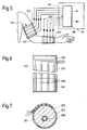
- FIGS. 5 and 7. An arm 301 with a large artery 303 is drawn in FIGS. 5 and 7.
- the device 311, likewise shown in FIG. 5, is designed to determine the blood pressure by detecting the electrical impedance or admittance.
- the device 311 has sensor means 313 with two sensors 321, 323 detachably attached to the arm 301, which in turn are spaced apart along the arm. For example, one, first sensor 321 is attached to the upper arm and the other, second sensor 323 is attached to the forearm.
- Each of the two sensors one of which can also be seen in FIGS. 6 and 7, has a sleeve 325 with a flexible, electrically insulating and possibly a little elastic band 327, which has four contact points on its side facing the arm when in use.
- Electrodes 329 is provided, which consist of flexible, electrically conductive metal foil strips running at a distance from one another parallel to the longitudinal direction of the tape.
- Velcro fastener elements 331, 333 are fastened to the band 327.
- the cuff 325 is used to carry out a measurement each sensor is wrapped around the arm 301 in such a way that the contact electrodes 329 abut it and completely surround it.
- the cuff is fastened at its overlapping end sections with the aid of the Velcro fastener elements 331, 333.
- a display and monitoring device 341 has electronic circuit means 343.
- Each contact electrode 329 is connected by a conductor of a cable to a feed and detector device 361 belonging to the circuit means 343.
- the latter has a generator or two generators in order to generate a supply voltage or a supply current with a frequency of 80 kHz to 100 kHz and to supply it to the two outermost electrodes of the two sensors 323.
- the or each generator can be designed to feed a current of constant amplitude into the arm 301 for each sensor.
- the feed and detector device 361 is further designed to detect the electrical impedance or admittance for each sensor from the electrical voltages that can be removed between the two inner electrodes of each sensor.
- the device 361 can furthermore form at least a first variable from the part of the impedance or admittance which changes in time with the pulse, which gives a measure of the volume.
- the volume of the blood in a blood vessel is proportional to its passage cross-sectional area and proportional to the square of the inner diameter of the blood vessel.
- the volumes, passage cross-sectional areas and diameter of the large arteries change - ie the brachial artery of the upper arm and the radial artery as well as the somewhat smaller ulnar artery of the forearm.
- the measurement of the impedance or admittance therefore also gives a measure of the passage cross-sectional area and of the inside diameter of at least one artery present in the measuring area.
- the electronic circuitry of device 341 may also be configured to be electrically through an analog or digital form of differentiation of the first derivative of the volume after time.
- the derivations or differential quotients determined for the two measuring ranges then each give a measure of the flow rate of the arterial blood in the arm regions detected by the two sensors.
- the device 311 thus makes it possible to determine a first size in the two measuring ranges, which gives a relative measure for the volume and / or the flow rate of the blood and / or for the passage cross-sectional area and / or the inside diameter of at least one blood vessel.
- the feed and detector device 361 is connected to an evaluation device (not shown) which, like the evaluation device 65, can determine the pulse wave speed from the time shift of the pulsating first variable detected by the two sensors.
- the evaluation device belonging to the electronic circuit means 343 can also be designed to determine the blood pressure from the measured values of the pulse wave velocity c pw measured in at least one measuring range for at least one of the variants measured as the first variable and the calibration values in an analogous manner to the evaluation device 65 blood pressure determined from v and c pw .
- the blood pressure according to the formula (5) would be proportional to the ratio Q / r4.
- Sensor means 413 which have two sensors 421, 423 for measuring the electrical impedance or admittance, are detachably attached to the arm 401 shown in FIG.
- the sensor means 413 differ from the sensor means 313 in that they have only six contact electrodes 429 in total. When measuring, the two outermost electrodes 429 introduce a high-frequency alternating current common to both sensors into the arm.
- the two sensors each have a cuff indicated by dash-dotted lines, but could also have a common cuff.
- the devices described with reference to FIGS. 5 to 8 can possibly still be changed by replacing some or all of the contact electrodes by electrodes which are electrically insulated from the body surface and which enclose the arm or another part of the body.
- the device could also be designed to measure the diameter of an artery, preferably a large artery, using ultrasound reflection as the first variable.
- the device can, for example, have sensors which, like sensors 121, 123, are provided with ultrasonic transducers 125.
- the electronic circuit means can then be designed to form electrical signals due to the reflection of ultrasound waves on at least a section of the arterial wall and preferably on two approximately diametrically opposed sections of the arterial wall, which signals measure the instantaneous values and / or temporal changes in the internal or external or average diameter or other cross-sectional dimensions and thus also the passage cross-sectional areas for the two sensors.
- the pulse wave speed can then be determined from the temporal shift between the periodic changes in the two sensors which are synchronous with the pulse and which result. Furthermore, blood pressure can be determined from the measured values and the entered calibration values. This can be done in a similar manner as was explained for the device 11 measuring the flow velocity described with reference to FIGS. 1 and 2.
- sensor means can also be provided which have only a single sensor for measuring the first variable.
- the pulse wave speed can then, for example - as also explained in the introduction - be determined from the influencing of the temporal course of the variables measured as the first variable caused by the reflection of the pulse waves.
- FIG. 9 contains two partial diagrams with a common abscissa, on which the time t is plotted.
- the flow velocity v is plotted on the ordinate in the upper part diagram.
- Curve 501 of the upper part diagram shows the somewhat schematic course of the flow velocity of the blood flowing through an artery during approximately one pulse period.
- the differential quotient dv / dt is plotted on the ordinate.
- curve 511 of the lower part diagram shows - likewise schematically - the course of the differential quotient mentioned.
- the flow velocity v begins to increase in the case of a heartbeat starting from a minimum value at time t o and reaches a main maximum 501a at time t 1, which coincides at least approximately with the occurrence of the systolic blood pressure.
- the flow velocity v then drops, reaches a relative intermediate minimum 501b at time t2, then rises again and reaches a secondary maximum 501c at time t3, in which the dicrotic node occurs in the blood pressure curve.
- the flow rate then drops again to approximately the initial minimum value.
- the curve 511 representing the course of the differential quotient dv / dt has accordingly at times t 1, t 2, t 3 each a zero crossing 511a or 511b or 511c, the zero line at zero crossings 511a and 511c from top to bottom and at Zero crossing 511b penetrates from bottom to top.
- the dicrotic knot and thus the associated secondary maximum 501c is caused by the interference of the primary pulse wave running away from the heart with a reflected pulse wave.
- the time difference T d between the two maxima 501a and 501c therefore gives a measure of the transit time of the reflected pulse waves and thus of the pulse wave speed.
- the electronic circuit means and in particular the evaluation device of the device provided for determining the pulse wave speed on the basis of the pulse wave reflection are designed to use the flow rate measured as the first variable to derive the first derivative over time - ie the differential quotient dv / dt - and preferably also the second derivative of time, ie to form the differential quotient d2v / dt2.
- This differentiation can be carried out electrically using a differentiating circuit in analog form or using a microprocessor in digital form.
- the circuit means can then identify the times t 1 and t 3 on the basis of the differential quotients and measure the time difference T d .
- the time difference T d or an associated variable, for example its reciprocal value, forms then the second quantity, which gives a measure of the pulse wave velocity, the value of which is represented in the form of a digital or analog, electrical signal.
- variable which gives a measure for the pulse wave velocity can be determined in a similar manner as was explained for the flow velocity v with reference to FIG.
- FIG. 10 shows a person with an arm 301 and a device for measuring blood pressure, designated 611 here.
- the sensor means 613 of the device 611 have only a single sensor 621 which is detachably attached to the arm 601. This has, for example, transducers for measuring the flow velocity by means of light or ultrasound, but could also be designed to determine a variable that can be used as the first variable by means of another measurement, for example an impedance or admittance measurement. However, the sensor means 613 still have contact electrodes, which are attached to the chest of the examined person and together form at least one sensor 623.
- the sensor 621 and the contact electrodes of the sensor 623 are connected to the display and monitoring device 641 via cables.
- the electronic circuit means of this are designed to detect at least one current of the heart muscle together with the contact electrodes of the sensor 623 analogously to electrocardiography and to determine the so-called R-wave of the cardiogram, in which the systole - ie the contraction of the Cardiac muscle - and the blood is emitted from the heart.
- the device 641 can then also determine the time difference between the R wave and the point in time at which the flow velocity of the blood in the arm 601 or the other first variable measured by the sensor 621 reaches the maximum value during a pulse period. These Time difference and its change or a quantity derived from this time difference and its change then give a measure of the pulse wave speed and its change.
- sensors can be provided which, like the sensors 21, 23, have light emitters and light receivers, but are arranged analogously to the sensors 121, 123 provided with an ultrasound transducer, in order to radiate light in a direction inclined towards the arm, so that then an optical Doppler effect measurement can be carried out.
- sensors can also be provided, each of which has a plurality of similar transducers which are offset from one another transversely to said artery. If such a sensor is attached, for example, to an arm containing the aforementioned large artery, it can be achieved without exact positioning of the sensor that the central radiation axis of one of its transducers crosses the large artery.
- the electronic circuit means can then be designed to automatically select the signal from the converter for further processing during measurement which is most strongly modulated by the pulse.
- the described devices and methods according to the invention all have the advantage that a long-term, continuous or at least quasi-continuous measurement of the blood pressure, for example taking place with every heartbeat, is possible, the examined person or possibly the examined animal being disturbed relatively little. It is particularly advantageous that only for A one-time calibration measurement or a few calibration measurements must or must be carried out using the Riva-Rocci method and that no cuff inflation and deflation is necessary for most of the measurement period.
- the method for blood pressure measurement and pulse rate measurement carried out using one of the described devices can be used commercially in therapy for long-term monitoring and furthermore, for example, also in examinations carried out in hospitals and possibly medical practices for the clarification of the general state of health, for human medicine as well as veterinary research and the development and testing of medicinal products are carried out.
Landscapes
- Health & Medical Sciences (AREA)
- Life Sciences & Earth Sciences (AREA)
- Cardiology (AREA)
- Molecular Biology (AREA)
- Animal Behavior & Ethology (AREA)
- Veterinary Medicine (AREA)
- Biophysics (AREA)
- Pathology (AREA)
- Engineering & Computer Science (AREA)
- Biomedical Technology (AREA)
- Heart & Thoracic Surgery (AREA)
- Medical Informatics (AREA)
- Public Health (AREA)
- Surgery (AREA)
- Physics & Mathematics (AREA)
- General Health & Medical Sciences (AREA)
- Hematology (AREA)
- Physiology (AREA)
- Vascular Medicine (AREA)
- Nuclear Medicine, Radiotherapy & Molecular Imaging (AREA)
- Radiology & Medical Imaging (AREA)
- Measuring Pulse, Heart Rate, Blood Pressure Or Blood Flow (AREA)
- Measurement And Recording Of Electrical Phenomena And Electrical Characteristics Of The Living Body (AREA)
- Ultra Sonic Daignosis Equipment (AREA)
- Measuring Fluid Pressure (AREA)
Applications Claiming Priority (2)
| Application Number | Priority Date | Filing Date | Title |
|---|---|---|---|
| CH2390/90 | 1990-07-18 | ||
| CH239090 | 1990-07-18 |
Publications (2)
| Publication Number | Publication Date |
|---|---|
| EP0467853A1 true EP0467853A1 (fr) | 1992-01-22 |
| EP0467853B1 EP0467853B1 (fr) | 1996-01-10 |
Family
ID=4232665
Family Applications (1)
| Application Number | Title | Priority Date | Filing Date |
|---|---|---|---|
| EP91810569A Expired - Lifetime EP0467853B1 (fr) | 1990-07-18 | 1991-07-15 | Dispositif et procédé destinés à la mesure de la pression sanguine |
Country Status (5)
| Country | Link |
|---|---|
| US (1) | US5309916A (fr) |
| EP (1) | EP0467853B1 (fr) |
| JP (1) | JP2750023B2 (fr) |
| AT (1) | ATE132720T1 (fr) |
| DE (1) | DE59107232D1 (fr) |
Cited By (19)
| Publication number | Priority date | Publication date | Assignee | Title |
|---|---|---|---|---|
| FR2703900A1 (fr) * | 1993-04-15 | 1994-10-21 | Zacouto Fred | Procédé pour établir les paramètres d'un système pulsatif notamment du système hémodynamique du corps d'un être vivant, et agencement pour la mise en Óoeuvre du procédé. |
| FR2704416A1 (fr) * | 1993-04-27 | 1994-11-04 | Labadie Dominique | Appareil électronique de mesure du temps de propagation de l'onde pulsatile (vélocité du pouls). |
| WO1994028794A1 (fr) * | 1993-06-08 | 1994-12-22 | Stu-Ert Medical Devices Limited | Test des maladies vasculaires peripheriques |
| WO1998017172A3 (fr) * | 1996-10-24 | 1998-07-23 | Massachusetts Inst Technology | Capteur d'annulaire surveillant un patient |
| EP0772998A3 (fr) * | 1995-11-06 | 1998-08-26 | Colin Corporation | Appareil destiné à la mesure de la vitesse de propagation de pulsations cardiaque |
| FR2790197A1 (fr) * | 1999-02-25 | 2000-09-01 | Novamed | Systeme de suivi de la pression arterielle |
| WO2000072750A1 (fr) * | 1999-06-01 | 2000-12-07 | Massachusetts Institute Of Technology | Appareil de mesure continue de la pression sanguine sans brassard |
| US6402690B1 (en) | 1999-04-23 | 2002-06-11 | Massachusetts Institute Of Technology | Isolating ring sensor design |
| DE10061189A1 (de) * | 2000-12-08 | 2002-06-27 | Ingo Stoermer | Verfahren zur kontinuierlichen, nicht-invasiven Bestimmung des arteriellen Blutdrucks |
| DE10114383A1 (de) * | 2001-03-23 | 2002-10-02 | Fresenius Medical Care De Gmbh | Blutdruckvorrichtung, Gerät zur extrakorporalen Blutbehandlung mit einer solchen Blutüberwachungsvorrichtung und Verfahren zur Blutdrucküberwachung |
| US6699199B2 (en) | 2000-04-18 | 2004-03-02 | Massachusetts Institute Of Technology | Photoplethysmograph signal-to-noise line enhancement |
| US6947781B2 (en) | 2002-12-13 | 2005-09-20 | Massachusetts Institute Of Technology | Vibratory venous and arterial oximetry sensor |
| EP2193745A1 (fr) * | 2008-12-04 | 2010-06-09 | Müller & Sebastiani Elektronik GmbH | Appareil de mesure de la pression sanguine longue durée |
| WO2010057495A3 (fr) * | 2008-11-18 | 2010-08-19 | Sense A/S | Procédés, appareil et capteur pour la mesure de grandeurs cardiovasculaires |
| WO2012087634A3 (fr) * | 2010-12-23 | 2012-09-07 | Draeger Medical Systems, Inc. | Dispositif et procédé pour une mesure non invasive continue de la pression sanguine et une oxymétrie pulsée (spo2) combinées |
| WO2015149822A1 (fr) * | 2014-04-04 | 2015-10-08 | Up-Med Gmbh | Procédé servant à déterminer la tension artérielle dans un vaisseau sanguin et dispositif servant à effectuer cette détermination |
| JP2016187618A (ja) * | 2011-02-17 | 2016-11-04 | クアルコム ライフ インコーポレイテッドQualcomm Life,Inc. | 哺乳動物の心血管の量を判定する方法およびシステム |
| DE102015109450A1 (de) * | 2015-06-12 | 2016-12-15 | Abb Schweiz Ag | Vorrichtung zur Messung des Drucks eines durch eine Rohrleitung strömendes Fluid |
| JP2017063892A (ja) * | 2015-09-28 | 2017-04-06 | 京セラ株式会社 | 測定装置及び測定システム |
Families Citing this family (196)
| Publication number | Priority date | Publication date | Assignee | Title |
|---|---|---|---|---|
| US5199424A (en) * | 1987-06-26 | 1993-04-06 | Sullivan Colin E | Device for monitoring breathing during sleep and control of CPAP treatment that is patient controlled |
| US6371921B1 (en) | 1994-04-15 | 2002-04-16 | Masimo Corporation | System and method of determining whether to recalibrate a blood pressure monitor |
| RU2118122C1 (ru) * | 1994-05-17 | 1998-08-27 | Воронежское высшее военное авиационное инженерное училище | Способы измерения скорости распространения пульсовой волны, артериального давления, температуры тела, содержания гемоглобина в крови и устройства для их осуществления |
| JP3318727B2 (ja) * | 1994-06-06 | 2002-08-26 | 日本光電工業株式会社 | 脈波伝播時間方式血圧計 |
| DE69532610T2 (de) * | 1994-10-13 | 2004-08-05 | Masimo Corp., Irvine | Automatisch aktivierte blutdruckmessvorrichtung |
| US5743857A (en) * | 1995-01-17 | 1998-04-28 | Colin Corporation | Blood pressure monitor apparatus |
| JP3580924B2 (ja) * | 1995-12-22 | 2004-10-27 | コーリンメディカルテクノロジー株式会社 | 動脈弾性度評価装置 |
| US6027452A (en) | 1996-06-26 | 2000-02-22 | Vital Insite, Inc. | Rapid non-invasive blood pressure measuring device |
| US6050950A (en) | 1996-12-18 | 2000-04-18 | Aurora Holdings, Llc | Passive/non-invasive systemic and pulmonary blood pressure measurement |
| JP3857788B2 (ja) | 1997-09-01 | 2006-12-13 | テルモ株式会社 | 循環器情報計測システム |
| JP3037266B2 (ja) * | 1998-05-13 | 2000-04-24 | 松下電器産業株式会社 | 非観血連続血圧計 |
| JP3046275B2 (ja) * | 1998-04-20 | 2000-05-29 | 松下電器産業株式会社 | 非観血連続血圧計 |
| JP2981208B1 (ja) * | 1998-06-01 | 1999-11-22 | 松下電器産業株式会社 | 非観血連続血圧計 |
| JP3037265B2 (ja) * | 1998-05-13 | 2000-04-24 | 松下電器産業株式会社 | 非観血連続血圧計 |
| IL128482A (en) * | 1999-02-11 | 2003-06-24 | Ultrasis Internat 1993 Ltd | Method and device for continuous analysis of cardiovascular activity of a subject |
| US6984207B1 (en) * | 1999-09-14 | 2006-01-10 | Hoana Medical, Inc. | Passive physiological monitoring (P2M) system |
| MXPA02003412A (es) * | 1999-10-07 | 2004-09-10 | K Mills Alexander | Dispositivo y metodo para la determinacion continua no invasora de caracteristica fisiologicas. |
| JP4505093B2 (ja) * | 1999-12-28 | 2010-07-14 | 株式会社 タウザー研究所 | 血圧測定装置 |
| JP4540784B2 (ja) * | 2000-01-07 | 2010-09-08 | 春江 劉 | 血圧測定方法及び血圧計 |
| AU2001221391A1 (en) | 2000-01-26 | 2001-08-07 | Vsm Medtech Ltd. | Continuous blood pressure monitoring method and apparatus |
| US6447459B1 (en) * | 2000-04-07 | 2002-09-10 | Pds Healthcare Products, Inc. | Device and method for measuring lung performance |
| GB0008883D0 (en) * | 2000-04-12 | 2000-05-31 | Univ Ulster | Bodily flow measuring system |
| US6616613B1 (en) | 2000-04-27 | 2003-09-09 | Vitalsines International, Inc. | Physiological signal monitoring system |
| US6475153B1 (en) * | 2000-05-10 | 2002-11-05 | Motorola Inc. | Method for obtaining blood pressure data from optical sensor |
| US6705990B1 (en) * | 2000-07-25 | 2004-03-16 | Tensys Medical, Inc. | Method and apparatus for monitoring physiologic parameters of a living subject |
| FR2812534B1 (fr) | 2000-08-03 | 2002-10-11 | France Etat | Dispositif et procede pour mesurer par effet doppler, l'evolution du diametre d'une veine |
| US6436038B1 (en) | 2000-08-11 | 2002-08-20 | Clarissa Engstrom | Animal vital signs monitoring system |
| US7666151B2 (en) | 2002-11-20 | 2010-02-23 | Hoana Medical, Inc. | Devices and methods for passive patient monitoring |
| US6423010B1 (en) * | 2000-10-04 | 2002-07-23 | Critikon Company, L.L.C. | Oscillometric blood pressure monitor with improved performance in the presence of arrhythmias |
| US6918879B2 (en) * | 2000-10-09 | 2005-07-19 | Healthstats International Pte. Ltd. | Method and device for monitoring blood pressure |
| SG94349A1 (en) * | 2000-10-09 | 2003-02-18 | Healthstats Int Pte Ltd | Method and device for monitoring blood pressure |
| JP2002238898A (ja) * | 2001-02-14 | 2002-08-27 | Aloka Co Ltd | 超音波探触子走査装置及び超音波診断装置 |
| DE10126539A1 (de) * | 2001-05-30 | 2002-12-05 | Friendly Sensors Ag | Vorrichtung zur Verformungs- und/oder Bewegungserfassung |
| JP3495348B2 (ja) * | 2001-07-02 | 2004-02-09 | 日本コーリン株式会社 | 脈波伝播速度情報測定装置 |
| US6893401B2 (en) * | 2001-07-27 | 2005-05-17 | Vsm Medtech Ltd. | Continuous non-invasive blood pressure monitoring method and apparatus |
| JP3530892B2 (ja) * | 2001-10-10 | 2004-05-24 | コーリンメディカルテクノロジー株式会社 | 血管障害診断装置 |
| US6953435B2 (en) | 2001-12-10 | 2005-10-11 | Kabushiki Gaisha K -And- S | Biological data observation apparatus |
| JP3621379B2 (ja) * | 2002-01-09 | 2005-02-16 | コーリンメディカルテクノロジー株式会社 | 動脈硬化評価装置 |
| US6648828B2 (en) * | 2002-03-01 | 2003-11-18 | Ge Medical Systems Information Technologies, Inc. | Continuous, non-invasive technique for measuring blood pressure using impedance plethysmography |
| WO2003082085A1 (fr) * | 2002-03-28 | 2003-10-09 | Heidelberg Engineering Optische Messsysteme Gmbh | Procede et dispositif pour examiner des vaisseaux |
| WO2003090617A1 (fr) * | 2002-04-24 | 2003-11-06 | Colin Corporation | Procede d'analyse d'une onde d'impulsion, logiciel d'analyse d'une onde d'impulsion, etc. |
| EP1388321A1 (fr) * | 2002-08-09 | 2004-02-11 | Instrumentarium Oyj | Procédé et systeme de mesure continue et non invasive de la pression sanguine |
| JP4269623B2 (ja) * | 2002-10-07 | 2009-05-27 | 株式会社 東北テクノアーチ | 血流可視化診断装置 |
| DE10249863A1 (de) * | 2002-10-25 | 2004-05-19 | Biosign Gmbh | Verfahren und Vorrichtung zur nicht invasiven Blutdruckmessung |
| JP4517619B2 (ja) * | 2002-12-05 | 2010-08-04 | オムロンヘルスケア株式会社 | 脈波測定装置 |
| US20050148882A1 (en) * | 2004-01-06 | 2005-07-07 | Triage Wireless, Incc. | Vital signs monitor used for conditioning a patient's response |
| US20060142648A1 (en) * | 2003-01-07 | 2006-06-29 | Triage Data Networks | Wireless, internet-based, medical diagnostic system |
| US6843771B2 (en) * | 2003-01-15 | 2005-01-18 | Salutron, Inc. | Ultrasonic monitor for measuring heart rate and blood flow rate |
| US7011631B2 (en) * | 2003-01-21 | 2006-03-14 | Hemonix, Inc. | Noninvasive method of measuring blood density and hematocrit |
| JP2007524468A (ja) * | 2003-06-26 | 2007-08-30 | ホアナ メディカル、インコーポレイテッド | 放射応力式非侵入型血圧測定方法 |
| US7559894B2 (en) * | 2003-09-18 | 2009-07-14 | New Paradigm Concepts, LLC | Multiparameter whole blood monitor and method |
| US7410550B2 (en) * | 2003-12-11 | 2008-08-12 | Sherwin Michael J | Flexible insulating sleeve |
| US7125383B2 (en) * | 2003-12-30 | 2006-10-24 | General Electric Company | Method and apparatus for ultrasonic continuous, non-invasive blood pressure monitoring |
| US20050216199A1 (en) * | 2004-03-26 | 2005-09-29 | Triage Data Networks | Cuffless blood-pressure monitor and accompanying web services interface |
| US7238159B2 (en) * | 2004-04-07 | 2007-07-03 | Triage Wireless, Inc. | Device, system and method for monitoring vital signs |
| US20050228244A1 (en) * | 2004-04-07 | 2005-10-13 | Triage Wireless, Inc. | Small-scale, vital-signs monitoring device, system and method |
| US20050228297A1 (en) * | 2004-04-07 | 2005-10-13 | Banet Matthew J | Wrist-worn System for Measuring Blood Pressure |
| US7004907B2 (en) * | 2004-04-07 | 2006-02-28 | Triage Wireless, Inc. | Blood-pressure monitoring device featuring a calibration-based analysis |
| US20050261598A1 (en) * | 2004-04-07 | 2005-11-24 | Triage Wireless, Inc. | Patch sensor system for measuring vital signs |
| US20060009697A1 (en) * | 2004-04-07 | 2006-01-12 | Triage Wireless, Inc. | Wireless, internet-based system for measuring vital signs from a plurality of patients in a hospital or medical clinic |
| US7179228B2 (en) * | 2004-04-07 | 2007-02-20 | Triage Wireless, Inc. | Cuffless system for measuring blood pressure |
| US20050228300A1 (en) * | 2004-04-07 | 2005-10-13 | Triage Data Networks | Cuffless blood-pressure monitor and accompanying wireless mobile device |
| US20060009698A1 (en) * | 2004-04-07 | 2006-01-12 | Triage Wireless, Inc. | Hand-held monitor for measuring vital signs |
| DE102004025042A1 (de) * | 2004-05-18 | 2005-12-29 | Schönfeld, Andreas, Dipl.-Ing. | Vorrichtung zur Bestimmung der Laufzeit eines Blutpulses |
| AU2004203059A1 (en) * | 2004-06-08 | 2005-12-22 | The Government Of The United States Of America As Represented By The Secretary Of The Department Of Health And Human Services, Centers For Disease Control And Prevention | Apparatus and method for assessing peripheral circulation to evaluate a physiological condition |
| US7324848B1 (en) | 2004-07-19 | 2008-01-29 | Pacesetter, Inc. | Reducing data acquisition, power and processing for photoplethysmography and other applications |
| US7909768B1 (en) * | 2004-07-19 | 2011-03-22 | Pacesetter, Inc. | Reducing data acquisition, power and processing for hemodynamic signal sampling |
| US20060020216A1 (en) * | 2004-07-20 | 2006-01-26 | Sharp Kabushiki Kaisha | Medical information detection apparatus and health management system using the medical information detection apparatus |
| US7381186B2 (en) * | 2004-08-02 | 2008-06-03 | The United States Of America As Represented By The Administrator Of The National Aeronautics And Space Administration | Method and apparatus to assess compartment syndrome |
| US9820658B2 (en) | 2006-06-30 | 2017-11-21 | Bao Q. Tran | Systems and methods for providing interoperability among healthcare devices |
| US7502498B2 (en) | 2004-09-10 | 2009-03-10 | Available For Licensing | Patient monitoring apparatus |
| US7683759B2 (en) * | 2004-10-06 | 2010-03-23 | Martis Ip Holdings, Llc | Patient identification system |
| US7609145B2 (en) * | 2004-10-06 | 2009-10-27 | Martis Ip Holdings, Llc | Test authorization system |
| US20080281635A1 (en) * | 2004-10-06 | 2008-11-13 | Martis Dinesh J | Method of administering a beneficiary medical procedure |
| US7946994B2 (en) | 2004-10-07 | 2011-05-24 | Tensys Medical, Inc. | Compact apparatus and methods for non-invasively measuring hemodynamic parameters |
| US20060084878A1 (en) * | 2004-10-18 | 2006-04-20 | Triage Wireless, Inc. | Personal computer-based vital signs monitor |
| US7658716B2 (en) * | 2004-12-07 | 2010-02-09 | Triage Wireless, Inc. | Vital signs monitor using an optical ear-based module |
| JP4981688B2 (ja) * | 2005-01-31 | 2012-07-25 | コーニンクレッカ フィリップス エレクトロニクス エヌ ヴィ | 医療センサのためのマルチコンダクタ接続デバイス |
| DE102005013429A1 (de) * | 2005-03-21 | 2006-09-28 | Flore, Ingo, Dr. | Mobiles Diagnosegerät |
| DE102005014048B4 (de) * | 2005-03-23 | 2010-08-12 | Gert Dr. Küchler | Verfahren und Gerät zur nichtinvasiven Blutdruckbestimmung |
| US20070016053A1 (en) * | 2005-06-08 | 2007-01-18 | Lo Thomas Y | Ultrasonic monitor with an adhesive member |
| EP2260756A1 (fr) | 2005-08-09 | 2010-12-15 | Flore, Ingo | Dispositif de mesure médical |
| US7674231B2 (en) * | 2005-08-22 | 2010-03-09 | Massachusetts Institute Of Technology | Wearable pulse wave velocity blood pressure sensor and methods of calibration thereof |
| CN101247757A (zh) * | 2005-08-26 | 2008-08-20 | 皇家飞利浦电子股份有限公司 | 脉搏波传导速度的测量 |
| US7733224B2 (en) | 2006-06-30 | 2010-06-08 | Bao Tran | Mesh network personal emergency response appliance |
| US7420472B2 (en) * | 2005-10-16 | 2008-09-02 | Bao Tran | Patient monitoring apparatus |
| JP4880972B2 (ja) * | 2005-10-20 | 2012-02-22 | セイコーインスツル株式会社 | 血液循環状態測定装置 |
| JP4880971B2 (ja) * | 2005-10-20 | 2012-02-22 | セイコーインスツル株式会社 | 血液循環状態測定装置 |
| IL185609A0 (en) * | 2007-08-30 | 2008-01-06 | Dan Furman | Multi function senssor |
| US20090221882A1 (en) * | 2005-12-08 | 2009-09-03 | Dan Gur Furman | Implantable Biosensor Assembly and Health Monitoring system and Method including same |
| US20070142715A1 (en) * | 2005-12-20 | 2007-06-21 | Triage Wireless, Inc. | Chest strap for measuring vital signs |
| US20070185393A1 (en) * | 2006-02-03 | 2007-08-09 | Triage Wireless, Inc. | System for measuring vital signs using an optical module featuring a green light source |
| FR2900560A1 (fr) * | 2006-05-04 | 2007-11-09 | Andrei Cividjian | Procede et dispositif non-invasif de mesure en continu de la pression arterielle |
| US8684922B2 (en) | 2006-05-12 | 2014-04-01 | Bao Tran | Health monitoring system |
| US8968195B2 (en) | 2006-05-12 | 2015-03-03 | Bao Tran | Health monitoring appliance |
| US7558622B2 (en) | 2006-05-24 | 2009-07-07 | Bao Tran | Mesh network stroke monitoring appliance |
| US9060683B2 (en) | 2006-05-12 | 2015-06-23 | Bao Tran | Mobile wireless appliance |
| US7539532B2 (en) | 2006-05-12 | 2009-05-26 | Bao Tran | Cuffless blood pressure monitoring appliance |
| US8323189B2 (en) | 2006-05-12 | 2012-12-04 | Bao Tran | Health monitoring appliance |
| US8500636B2 (en) | 2006-05-12 | 2013-08-06 | Bao Tran | Health monitoring appliance |
| CA2655049A1 (fr) | 2006-05-13 | 2007-11-22 | Tensys Medical, Inc. | Appareil et procedes e positionnement en continu |
| US8684900B2 (en) | 2006-05-16 | 2014-04-01 | Bao Tran | Health monitoring appliance |
| US7539533B2 (en) | 2006-05-16 | 2009-05-26 | Bao Tran | Mesh network monitoring appliance |
| EP2462864B1 (fr) | 2006-05-24 | 2014-10-15 | Tarilian Laser Technologies, Limited | Procédé de détection d'un signe vital optique et dispositif de mesure |
| US20080071180A1 (en) * | 2006-05-24 | 2008-03-20 | Tarilian Laser Technologies, Limited | Vital Sign Detection Method and Measurement Device |
| US7993275B2 (en) * | 2006-05-25 | 2011-08-09 | Sotera Wireless, Inc. | Bilateral device, system and method for monitoring vital signs |
| US9149192B2 (en) * | 2006-05-26 | 2015-10-06 | Sotera Wireless, Inc. | System for measuring vital signs using bilateral pulse transit time |
| US8905939B2 (en) * | 2006-07-13 | 2014-12-09 | Edwards Lifesciences Corporation | Method and apparatus for continuous assessment of a cardiovascular parameter using the arterial pulse pressure propagation time and waveform |
| EP2049012B1 (fr) * | 2006-08-02 | 2015-04-15 | Philips Intellectual Property & Standards GmbH | Détecteur du passage d'une onde d'impulsion provenant du système artériel d'un sujet |
| US8442607B2 (en) * | 2006-09-07 | 2013-05-14 | Sotera Wireless, Inc. | Hand-held vital signs monitor |
| US20080082004A1 (en) * | 2006-09-08 | 2008-04-03 | Triage Wireless, Inc. | Blood pressure monitor |
| US8449469B2 (en) * | 2006-11-10 | 2013-05-28 | Sotera Wireless, Inc. | Two-part patch sensor for monitoring vital signs |
| KR101451448B1 (ko) * | 2006-11-23 | 2014-10-23 | 플로레, 잉고 | 의료 측정 기구 |
| JP2008136655A (ja) * | 2006-12-01 | 2008-06-19 | Omron Healthcare Co Ltd | 脈波測定用電極ユニットおよび脈波測定装置 |
| US20080167563A1 (en) * | 2007-01-08 | 2008-07-10 | Juvent, Inc. | Non-invasive blood flow monitor |
| CN102519500B (zh) | 2007-01-31 | 2015-08-12 | 泰瑞连激光技术有限公司 | 光功率调制 |
| US20080221399A1 (en) * | 2007-03-05 | 2008-09-11 | Triage Wireless, Inc. | Monitor for measuring vital signs and rendering video images |
| US20080221461A1 (en) * | 2007-03-05 | 2008-09-11 | Triage Wireless, Inc. | Vital sign monitor for cufflessly measuring blood pressure without using an external calibration |
| US20080306387A1 (en) * | 2007-04-13 | 2008-12-11 | Schutz Ronald W | Finger mounted imaging and sensing assembly |
| US7884727B2 (en) | 2007-05-24 | 2011-02-08 | Bao Tran | Wireless occupancy and day-light sensing |
| US20100130875A1 (en) * | 2008-06-18 | 2010-05-27 | Triage Wireless, Inc. | Body-worn system for measuring blood pressure |
| US12245852B2 (en) | 2007-06-12 | 2025-03-11 | Sotera Wireless, Inc. | Optical sensors for use in vital sign monitoring |
| US20080319327A1 (en) * | 2007-06-25 | 2008-12-25 | Triage Wireless, Inc. | Body-worn sensor featuring a low-power processor and multi-sensor array for measuring blood pressure |
| US7920913B1 (en) | 2007-06-29 | 2011-04-05 | Pacesetter, Inc. | Systems and methods for increasing implantable sensor accuracy |
| WO2009029386A1 (fr) * | 2007-08-02 | 2009-03-05 | Neuro Diagnostic Devices, Inc. | Capteur de pression intracrânienne non invasif |
| WO2009033625A1 (fr) * | 2007-09-07 | 2009-03-19 | Flore, Ingo | Dispositif de mesure médical pour mesure d'impédance bioélectrique |
| CN101896117B (zh) | 2007-10-12 | 2015-03-04 | 坦西斯医药股份有限公司 | 用于非侵入式测量病人动脉血压的设备和方法 |
| US20090118628A1 (en) * | 2007-11-01 | 2009-05-07 | Triage Wireless, Inc. | System for measuring blood pressure featuring a blood pressure cuff comprising size information |
| EP2074942B1 (fr) | 2007-12-21 | 2012-02-01 | CSEM Centre Suisse d'Electronique et de Microtechnique SA - Recherche et Développement | Procédé et appareil pour la surveillance continue non invasive et non obstructive de la tension artérielle |
| JP5098721B2 (ja) * | 2008-03-14 | 2012-12-12 | オムロンヘルスケア株式会社 | 血圧測定装置、血圧導出プログラムおよび血圧導出方法 |
| DE102009011381A1 (de) | 2009-03-05 | 2010-09-09 | Flore, Ingo, Dr. | Diagnostische Messvorrichtung |
| US8313439B2 (en) * | 2009-03-20 | 2012-11-20 | Massachusetts Institute Of Technology | Calibration of pulse transit time measurements to arterial blood pressure using external arterial pressure applied along the pulse transit path |
| ITPI20090099A1 (it) * | 2009-07-31 | 2011-02-01 | Cnr Consiglio Naz Delle Ric Erche | Apparecchiatura per la misura della velocità di propagazione di un'onda pressoria nel sistema arterioso |
| AT508114B1 (de) | 2009-09-03 | 2010-11-15 | Heller Arnulf Dipl Ing | Vorrichtung zur nicht-invasiven bestimmung des arteriellen blutdrucks |
| JP5884256B2 (ja) * | 2010-05-19 | 2016-03-15 | セイコーエプソン株式会社 | 血圧測定装置及び血圧測定方法 |
| US9408542B1 (en) * | 2010-07-22 | 2016-08-09 | Masimo Corporation | Non-invasive blood pressure measurement system |
| PL2433561T3 (pl) * | 2010-09-27 | 2015-05-29 | King’S Metal Fiber Tech Co Ltd | Ubiór z trójwymiarowym zestawem elektrod nadających się do noszenia |
| TWI420723B (zh) * | 2011-03-25 | 2013-12-21 | Tex Ray Ind Co Ltd | 穿戴式電池組 |
| JP5686030B2 (ja) * | 2011-04-20 | 2015-03-18 | セイコーエプソン株式会社 | 超音波測定装置、及び超音波測定方法 |
| JP5766569B2 (ja) * | 2011-09-27 | 2015-08-19 | 株式会社東芝 | 脈波伝播速度計測装置 |
| JP5927889B2 (ja) * | 2011-12-14 | 2016-06-01 | セイコーエプソン株式会社 | 血圧計測装置及び血圧計測方法 |
| WO2013090850A1 (fr) * | 2011-12-14 | 2013-06-20 | California Institute Of Technology | Systèmes non invasifs de mesure de la pression sanguine artérielle |
| KR20140107407A (ko) | 2011-12-22 | 2014-09-04 | 캘리포니아 인스티튜트 오브 테크놀로지 | 고유 주파수 혈류역학 파형 분석 |
| JP5821658B2 (ja) * | 2012-01-25 | 2015-11-24 | オムロンヘルスケア株式会社 | 測定装置および測定方法 |
| JP6028897B2 (ja) * | 2012-04-18 | 2016-11-24 | セイコーエプソン株式会社 | 血圧計測装置および血圧推定パラメーター校正方法 |
| JP5900129B2 (ja) * | 2012-04-18 | 2016-04-06 | セイコーエプソン株式会社 | 血圧推定パラメーター校正方法、血圧計測方法及び血圧計測装置 |
| JP6028898B2 (ja) * | 2012-04-18 | 2016-11-24 | セイコーエプソン株式会社 | 血圧計測装置、血圧推定パラメーター校正方法及び血圧計測方法 |
| KR20130123597A (ko) * | 2012-05-03 | 2013-11-13 | 삼성전자주식회사 | 휴대용 혈압 측정 장치 및 휴대 단말에서의 혈압 측정 방법 |
| US20140081098A1 (en) * | 2012-09-14 | 2014-03-20 | Nellcor Puritan Bennett Llc | Sensor system |
| WO2014074901A1 (fr) * | 2012-11-08 | 2014-05-15 | Thai Le | Dispositif et méthode de surveillance améliorés pour la pression sanguine |
| US9877659B2 (en) | 2012-11-30 | 2018-01-30 | Industrial Technology Research Institute | Sensing system and method for physiology measurements |
| US9865176B2 (en) | 2012-12-07 | 2018-01-09 | Koninklijke Philips N.V. | Health monitoring system |
| ITRM20130384A1 (it) * | 2013-06-28 | 2014-12-29 | Diagnostic Engineering Solutions S R L | Dispositivo indossabile per la misurazione del flusso sanguigno, e relativo sistema. |
| US20150099988A1 (en) * | 2013-10-07 | 2015-04-09 | Andre Cernasov | Blood viscosity measuring method and system |
| CA2927671A1 (fr) | 2013-10-18 | 2015-04-23 | California Institute Of Technology | Analyse de frequence intrinseque de la fraction d'ejection du ventricule gauche ou determination du debit systolique |
| CN103610454B (zh) * | 2013-12-06 | 2017-01-11 | 黄志海 | 一种血压测量方法及系统 |
| US20150297105A1 (en) | 2014-01-21 | 2015-10-22 | California Institute Of Technology | Portable electronic hemodynamic sensor systems |
| CN106456059A (zh) * | 2014-05-12 | 2017-02-22 | 皇家飞利浦有限公司 | 运动触发的生命体征测量 |
| US10039455B2 (en) * | 2014-05-19 | 2018-08-07 | Qualcomm Incorporated | Continuous calibration of a blood pressure measurement device |
| EP3157416B1 (fr) * | 2014-06-20 | 2020-07-15 | Healthcare Technology Innovation Centre | Système de mesure de la pression sanguine sans brassard d'un sujet |
| US11169988B2 (en) | 2014-08-22 | 2021-11-09 | Google Llc | Radar recognition-aided search |
| US9778749B2 (en) | 2014-08-22 | 2017-10-03 | Google Inc. | Occluded gesture recognition |
| US9600080B2 (en) | 2014-10-02 | 2017-03-21 | Google Inc. | Non-line-of-sight radar-based gesture recognition |
| AU2015337767B2 (en) * | 2014-10-27 | 2019-11-28 | Vital Sines International Inc. | System and method for monitoring aortic pulse wave velocity and blood pressure |
| US11622730B2 (en) | 2014-11-17 | 2023-04-11 | Rochester Institute Of Technology | Pulse wave velocity, arterial compliance, and blood pressure |
| US10016162B1 (en) | 2015-03-23 | 2018-07-10 | Google Llc | In-ear health monitoring |
| US9848780B1 (en) * | 2015-04-08 | 2017-12-26 | Google Inc. | Assessing cardiovascular function using an optical sensor |
| EP3289432B1 (fr) | 2015-04-30 | 2019-06-12 | Google LLC | Suivi de micro-mouvements sur la base de rf pour suivi et reconnaissance de gestes |
| JP6582199B2 (ja) * | 2015-05-25 | 2019-10-02 | セイコーエプソン株式会社 | 血圧計測装置及び血圧計測方法 |
| US10842464B2 (en) * | 2015-05-28 | 2020-11-24 | Koninklijke Philips N.V. | Apparatus and method for determining blood flow velocity |
| CN107613855B (zh) * | 2015-05-29 | 2021-11-23 | 京瓷株式会社 | 电子设备 |
| JP6482440B2 (ja) * | 2015-09-28 | 2019-03-13 | 京セラ株式会社 | 測定装置及び測定システム |
| US10244952B2 (en) | 2015-09-28 | 2019-04-02 | Kyocera Corporation | Measuring apparatus and measuring system |
| US10817065B1 (en) | 2015-10-06 | 2020-10-27 | Google Llc | Gesture recognition using multiple antenna |
| CN105286919B (zh) * | 2015-10-13 | 2018-06-22 | 广州丰谱信息技术有限公司 | 基于心脏点波动传导特性的血管状态检测方法与装置 |
| EP3175786A1 (fr) | 2015-12-01 | 2017-06-07 | Panasonic Intellectual Property Corporation of America | Estimation de conditions physiques |
| EP3383267B1 (fr) | 2015-12-02 | 2023-02-22 | Spry Health, Inc. | Systèmes et procédés de mesure de fréquence respiratoire non-invasive |
| US11020058B2 (en) * | 2016-02-12 | 2021-06-01 | Qualcomm Incorporated | Methods and devices for calculating blood pressure based on measurements of arterial blood flow and arterial lumen |
| JP6761337B2 (ja) * | 2016-12-28 | 2020-09-23 | オムロン株式会社 | 脈波測定装置および脈波測定方法、並びに血圧測定装置 |
| WO2018136135A1 (fr) | 2017-01-18 | 2018-07-26 | Physio-Control, Inc. | Mesure non invasive de la pression sanguine à l'aide d'ultrasons |
| JP6837881B2 (ja) * | 2017-03-15 | 2021-03-03 | オムロン株式会社 | 生体情報測定装置、方法及びプログラム |
| US10548487B2 (en) * | 2017-04-24 | 2020-02-04 | Monovo, LLC | Wearable vital sign monitor |
| US11413005B2 (en) * | 2017-08-14 | 2022-08-16 | Stryker Corporation | Constitutive equation for non-invasive blood pressure measurement systems and methods |
| US11317805B2 (en) | 2017-09-13 | 2022-05-03 | Battelle Memorial Institute | Wearable health monitoring device |
| US11357415B2 (en) | 2017-10-27 | 2022-06-14 | Stryker Corporation | Light-based non-invasive blood pressure systems and methods |
| JP2019110987A (ja) * | 2017-12-21 | 2019-07-11 | オムロンヘルスケア株式会社 | 測定装置およびプログラム |
| CN108113707A (zh) * | 2017-12-21 | 2018-06-05 | 潍坊医学院 | 一种心血管血液流速传感器 |
| AU2018391014B2 (en) | 2017-12-22 | 2024-05-16 | Assistance Publique - Hopitaux De Paris | System for measuring the mean arterial pressure |
| WO2020117737A1 (fr) * | 2018-12-03 | 2020-06-11 | Duke University | Systèmes, dispositifs et méthodes de surveillance non invase de la tension artérielle d'un utilisateur |
| US11534071B2 (en) * | 2019-04-12 | 2022-12-27 | Beijing Shunyuan Kaihua Technology Limited | Blood pressure measurement |
| EP4516237A3 (fr) * | 2020-05-19 | 2025-04-16 | Coravie Medical, Inc. | Systèmes de surveillance hémodynamique injectables |
| US11800986B2 (en) | 2020-12-28 | 2023-10-31 | Industrial Technology Research Institute | Non-pressure continuous blood pressure measuring device and method |
| CN114903525B (zh) * | 2021-02-08 | 2025-02-07 | 深圳迈瑞生物医疗电子股份有限公司 | 基于超声血流成像的测量方法和超声血流成像装置 |
| EP4395634A4 (fr) * | 2021-08-30 | 2025-05-21 | TopSight Monitoring Ltd | Système de surveillance physiologique portable |
| US20230125180A1 (en) * | 2021-10-21 | 2023-04-27 | Walnut Medical Private Limited | Blood pressure measurement system utilizing auscultatory signal acquisition |
| CN115462831A (zh) * | 2022-09-02 | 2022-12-13 | 南京师范大学 | 一种基于超声和心电联用测量血压及动脉血管弹性模量的系统及其测量方法 |
Citations (5)
| Publication number | Priority date | Publication date | Assignee | Title |
|---|---|---|---|---|
| DE1905620A1 (de) * | 1969-02-05 | 1970-08-20 | Siemens Ag | Geraet zur Messung der Pulswellengeschwindigkeit |
| EP0027215A1 (fr) * | 1979-10-15 | 1981-04-22 | Fraunhofer-Gesellschaft Zur Förderung Der Angewandten Forschung E.V. | Cardiotachomètre |
| FR2481917A1 (fr) * | 1979-08-14 | 1981-11-13 | Inst Nat Sante Rech Med | Procede et appareil de mesure de la celerite de l'onde pulsatile arterielle pour le diagnostic des maladies arterielles |
| US4370985A (en) * | 1979-04-26 | 1983-02-01 | Kuniyasu Kodaira | Medical measuring apparatus |
| FR2523432A1 (fr) * | 1982-03-17 | 1983-09-23 | Jozon Martine | Procede de mesure de la pression arterielle par voie externe |
Family Cites Families (17)
| Publication number | Priority date | Publication date | Assignee | Title |
|---|---|---|---|---|
| JPS5033676A (fr) * | 1973-07-30 | 1975-03-31 | ||
| JPS52146987A (en) * | 1976-06-01 | 1977-12-07 | Yoshihisa Ushiyama | Digital pulse wave propagation speedometer |
| JPS54127399A (en) * | 1978-03-27 | 1979-10-03 | Yoshimura Shiyouzou | Compensated propagation velocity calculator |
| DE2829269C3 (de) * | 1978-07-04 | 1981-11-05 | Ewald Max Christian Dipl.-Phys. 6000 Frankfurt Hennig | Verfahren zur Bestimmung von kardiologischen Meßgrößen und Vorrichtung zur Durchführung des Verfahrens |
| US4562843A (en) * | 1980-09-29 | 1986-01-07 | Ljubomir Djordjevich | System for determining characteristics of blood flow |
| US4703758A (en) * | 1982-09-30 | 1987-11-03 | Yoshiaki Omura | Non-invasive monitoring of blood flow and cerebral blood pressure using ultra miniature reflection type photoelectric plethysmographic sensors or ultrasonic doppler flow meter |
| JPS60198128A (ja) * | 1984-03-21 | 1985-10-07 | 横須賀 甫 | 血流測定装置 |
| US5111826A (en) * | 1984-12-07 | 1992-05-12 | Nasiff Roger E | Indirect continuous blood pressure method |
| JPS6382623A (ja) * | 1986-09-27 | 1988-04-13 | 日立建機株式会社 | 頭蓋内圧の測定装置 |
| US4807638A (en) * | 1987-10-21 | 1989-02-28 | Bomed Medical Manufacturing, Ltd. | Noninvasive continuous mean arterial blood prssure monitor |
| US4873987A (en) * | 1988-06-30 | 1989-10-17 | Ljubomir Djordjevich | Noninvasive continuous monitor of arterial blood pressure waveform |
| JP2579665B2 (ja) * | 1988-07-07 | 1997-02-05 | コーリン電子株式会社 | 血管径測定装置 |
| JPH02126830A (ja) * | 1988-11-07 | 1990-05-15 | Nippon Koden Corp | 非観血式自動血圧測定装置 |
| US5111817A (en) * | 1988-12-29 | 1992-05-12 | Medical Physics, Inc. | Noninvasive system and method for enhanced arterial oxygen saturation determination and arterial blood pressure monitoring |
| JPH02213324A (ja) * | 1989-02-14 | 1990-08-24 | Masayoshi Matsuda | 血圧および脈波移動時間測定用縛帯 |
| CH678690A5 (fr) * | 1989-03-08 | 1991-10-31 | Asulab Sa | |
| JPH03164043A (ja) * | 1989-11-21 | 1991-07-16 | Toshiba Corp | ポニーモータ駆動装置 |
-
1991
- 1991-07-15 DE DE59107232T patent/DE59107232D1/de not_active Expired - Fee Related
- 1991-07-15 AT AT91810569T patent/ATE132720T1/de not_active IP Right Cessation
- 1991-07-15 EP EP91810569A patent/EP0467853B1/fr not_active Expired - Lifetime
- 1991-07-16 US US07/730,596 patent/US5309916A/en not_active Expired - Fee Related
- 1991-07-18 JP JP3178378A patent/JP2750023B2/ja not_active Expired - Fee Related
Patent Citations (5)
| Publication number | Priority date | Publication date | Assignee | Title |
|---|---|---|---|---|
| DE1905620A1 (de) * | 1969-02-05 | 1970-08-20 | Siemens Ag | Geraet zur Messung der Pulswellengeschwindigkeit |
| US4370985A (en) * | 1979-04-26 | 1983-02-01 | Kuniyasu Kodaira | Medical measuring apparatus |
| FR2481917A1 (fr) * | 1979-08-14 | 1981-11-13 | Inst Nat Sante Rech Med | Procede et appareil de mesure de la celerite de l'onde pulsatile arterielle pour le diagnostic des maladies arterielles |
| EP0027215A1 (fr) * | 1979-10-15 | 1981-04-22 | Fraunhofer-Gesellschaft Zur Förderung Der Angewandten Forschung E.V. | Cardiotachomètre |
| FR2523432A1 (fr) * | 1982-03-17 | 1983-09-23 | Jozon Martine | Procede de mesure de la pression arterielle par voie externe |
Cited By (25)
| Publication number | Priority date | Publication date | Assignee | Title |
|---|---|---|---|---|
| US5803907A (en) * | 1992-06-08 | 1998-09-08 | Stu-Ert Medical Devices Limited | Peripheral vascular disease testing |
| FR2703900A1 (fr) * | 1993-04-15 | 1994-10-21 | Zacouto Fred | Procédé pour établir les paramètres d'un système pulsatif notamment du système hémodynamique du corps d'un être vivant, et agencement pour la mise en Óoeuvre du procédé. |
| FR2704416A1 (fr) * | 1993-04-27 | 1994-11-04 | Labadie Dominique | Appareil électronique de mesure du temps de propagation de l'onde pulsatile (vélocité du pouls). |
| WO1994028794A1 (fr) * | 1993-06-08 | 1994-12-22 | Stu-Ert Medical Devices Limited | Test des maladies vasculaires peripheriques |
| EP0772998A3 (fr) * | 1995-11-06 | 1998-08-26 | Colin Corporation | Appareil destiné à la mesure de la vitesse de propagation de pulsations cardiaque |
| WO1998017172A3 (fr) * | 1996-10-24 | 1998-07-23 | Massachusetts Inst Technology | Capteur d'annulaire surveillant un patient |
| US5964701A (en) * | 1996-10-24 | 1999-10-12 | Massachusetts Institute Of Technology | Patient monitoring finger ring sensor |
| FR2790197A1 (fr) * | 1999-02-25 | 2000-09-01 | Novamed | Systeme de suivi de la pression arterielle |
| US6402690B1 (en) | 1999-04-23 | 2002-06-11 | Massachusetts Institute Of Technology | Isolating ring sensor design |
| WO2000072750A1 (fr) * | 1999-06-01 | 2000-12-07 | Massachusetts Institute Of Technology | Appareil de mesure continue de la pression sanguine sans brassard |
| US6699199B2 (en) | 2000-04-18 | 2004-03-02 | Massachusetts Institute Of Technology | Photoplethysmograph signal-to-noise line enhancement |
| DE10061189A1 (de) * | 2000-12-08 | 2002-06-27 | Ingo Stoermer | Verfahren zur kontinuierlichen, nicht-invasiven Bestimmung des arteriellen Blutdrucks |
| DE10114383B4 (de) * | 2001-03-23 | 2010-09-23 | Fresenius Medical Care Deutschland Gmbh | Blutdruckvorrichtung und Gerät zur extrakorporalen Blutbehandlung mit einer solchen Blutüberwachungsvorrichtung |
| DE10114383A1 (de) * | 2001-03-23 | 2002-10-02 | Fresenius Medical Care De Gmbh | Blutdruckvorrichtung, Gerät zur extrakorporalen Blutbehandlung mit einer solchen Blutüberwachungsvorrichtung und Verfahren zur Blutdrucküberwachung |
| US6947781B2 (en) | 2002-12-13 | 2005-09-20 | Massachusetts Institute Of Technology | Vibratory venous and arterial oximetry sensor |
| US9138161B2 (en) | 2008-11-18 | 2015-09-22 | Qualcomm Incorporated | Methods, apparatus and sensor for measurement of cardiovascular quantities |
| WO2010057495A3 (fr) * | 2008-11-18 | 2010-08-19 | Sense A/S | Procédés, appareil et capteur pour la mesure de grandeurs cardiovasculaires |
| EP2193745A1 (fr) * | 2008-12-04 | 2010-06-09 | Müller & Sebastiani Elektronik GmbH | Appareil de mesure de la pression sanguine longue durée |
| WO2012087634A3 (fr) * | 2010-12-23 | 2012-09-07 | Draeger Medical Systems, Inc. | Dispositif et procédé pour une mesure non invasive continue de la pression sanguine et une oxymétrie pulsée (spo2) combinées |
| US9839362B2 (en) | 2010-12-23 | 2017-12-12 | Draeger Medical Systems, Inc. | Device and method for combined continuous non-invasive measurement of blood pressure and pulse oximetry (SpO2) |
| JP2016187618A (ja) * | 2011-02-17 | 2016-11-04 | クアルコム ライフ インコーポレイテッドQualcomm Life,Inc. | 哺乳動物の心血管の量を判定する方法およびシステム |
| WO2015149822A1 (fr) * | 2014-04-04 | 2015-10-08 | Up-Med Gmbh | Procédé servant à déterminer la tension artérielle dans un vaisseau sanguin et dispositif servant à effectuer cette détermination |
| DE102015109450A1 (de) * | 2015-06-12 | 2016-12-15 | Abb Schweiz Ag | Vorrichtung zur Messung des Drucks eines durch eine Rohrleitung strömendes Fluid |
| US10732063B2 (en) | 2015-06-12 | 2020-08-04 | Abb Schweiz Ag | Device for measuring the pressure of a fluid flowing through a pipeline |
| JP2017063892A (ja) * | 2015-09-28 | 2017-04-06 | 京セラ株式会社 | 測定装置及び測定システム |
Also Published As
| Publication number | Publication date |
|---|---|
| ATE132720T1 (de) | 1996-01-15 |
| JP2750023B2 (ja) | 1998-05-13 |
| EP0467853B1 (fr) | 1996-01-10 |
| US5309916A (en) | 1994-05-10 |
| JPH04250135A (ja) | 1992-09-07 |
| DE59107232D1 (de) | 1996-02-22 |
Similar Documents
| Publication | Publication Date | Title |
|---|---|---|
| EP0467853B1 (fr) | Dispositif et procédé destinés à la mesure de la pression sanguine | |
| DE69632317T2 (de) | Vorrichtung zum messen der verfassung eines lebenden körpers | |
| DE112009000339B4 (de) | Blutdruckinformationsmessvorrichtung und Detektiereinheit für Blutdruckinformationsmessvorrichtung | |
| DE60035470T2 (de) | Verfahren und Vorrichtung zur Bestimmung des Herzzeitvolumens oder des totalen peripheren Widerstandes | |
| DE69618654T2 (de) | Gerät und verfahren zur messung einer induzierten störung zur bestimmung des blutdrucks | |
| DE68923051T2 (de) | Verfahren und vorrichtung zur bestimmung des blutdrucks und des herzzustandes. | |
| DE3807672C2 (fr) | ||
| EP2240072B1 (fr) | Manomètre, en particulier sphygmomanomètre, procédé de détermination de valeurs de pression, procédé d'étalonnage d'un manomètre et programme informatique pour la mise en oeuvre de ces procédés | |
| EP3125743B1 (fr) | Procédé servant à déterminer la tension artérielle dans un vaisseau sanguin et dispositif servant à effectuer cette détermination | |
| DE69835843T2 (de) | Pulswellen-Untersuchungsgerät | |
| DE60035214T2 (de) | Verfahren zur messung einer induzierten störung zur bestimmung eines physiologischen parameters | |
| DE60215283T2 (de) | Vorrichtung zur Festlegung der linksventrikulären Auswurfzeit in einem Herz | |
| DE69424085T2 (de) | Vorrichtung zur Messung der Gefäss-Funktion | |
| DE10209027A1 (de) | Blutstromvolumenmessverfahren und Vitalfunktionsüberwachungsvorrichtung | |
| EP0063649A1 (fr) | Dispositif de mesure non invasive de troubles d'écoulement et de circulation dans les veines et les artères | |
| AT502921A2 (de) | Gerät zur messung von herz- und gefässfunktion (function) und körperräumen (spaces) mit hilfe der impedanzmessung | |
| EP2473101B1 (fr) | Dispositif pour la détermination non invasive de la tension artérielle | |
| EP3071098B1 (fr) | Procédé et appareil pour déterminer au moins un paramètre physiologique au moyen d'un signal de mesure du pouls corrigé | |
| DE60036080T2 (de) | Verfahren und vorrichtung zur kontinuierlichen analyse cardiovaskulärer aktivität in einem subjekt | |
| DE69532610T2 (de) | Automatisch aktivierte blutdruckmessvorrichtung | |
| DE69634901T2 (de) | Vorrichtung zum messen induzierter störsingnale zum bestimmen des physiologischen zustandes des menschlichen arterien-systems | |
| DE10249863A1 (de) | Verfahren und Vorrichtung zur nicht invasiven Blutdruckmessung | |
| WO2009013287A1 (fr) | Procédé pour déterminer une modification quasi continue de la pression sanguine dans un flux sanguin pulsatile | |
| AT524040B1 (de) | Verfahren und messvorrichtung zur kontinuierlichen, nicht-invasiven bestimmung zumindest eines herz-kreislaufparameters | |
| DE102011122700A1 (de) | Bewegungskorreliertes Verfahren und optisch-elektronische Vorrichtung zur nichtinvasiven Bestimmung der dermalvenösen Sauerstoffversorgung peripherer Beingebiete |
Legal Events
| Date | Code | Title | Description |
|---|---|---|---|
| PUAI | Public reference made under article 153(3) epc to a published international application that has entered the european phase |
Free format text: ORIGINAL CODE: 0009012 |
|
| AK | Designated contracting states |
Kind code of ref document: A1 Designated state(s): AT CH DE FR GB LI |
|
| 17P | Request for examination filed |
Effective date: 19920703 |
|
| RAP1 | Party data changed (applicant data changed or rights of an application transferred) |
Owner name: AVL MEDICAL INSTRUMENTS AG |
|
| 17Q | First examination report despatched |
Effective date: 19940420 |
|
| GRAA | (expected) grant |
Free format text: ORIGINAL CODE: 0009210 |
|
| AK | Designated contracting states |
Kind code of ref document: B1 Designated state(s): AT CH DE FR GB LI |
|
| REF | Corresponds to: |
Ref document number: 132720 Country of ref document: AT Date of ref document: 19960115 Kind code of ref document: T |
|
| ET | Fr: translation filed | ||
| GBT | Gb: translation of ep patent filed (gb section 77(6)(a)/1977) |
Effective date: 19960122 |
|
| REF | Corresponds to: |
Ref document number: 59107232 Country of ref document: DE Date of ref document: 19960222 |
|
| PG25 | Lapsed in a contracting state [announced via postgrant information from national office to epo] |
Ref country code: AT Effective date: 19960715 |
|
| PG25 | Lapsed in a contracting state [announced via postgrant information from national office to epo] |
Ref country code: LI Effective date: 19960731 Ref country code: CH Effective date: 19960731 |
|
| PLBQ | Unpublished change to opponent data |
Free format text: ORIGINAL CODE: EPIDOS OPPO |
|
| PLBQ | Unpublished change to opponent data |
Free format text: ORIGINAL CODE: EPIDOS OPPO |
|
| PLBI | Opposition filed |
Free format text: ORIGINAL CODE: 0009260 |
|
| PLBF | Reply of patent proprietor to notice(s) of opposition |
Free format text: ORIGINAL CODE: EPIDOS OBSO |
|
| 26 | Opposition filed |
Opponent name: DR. WALTER SCHMID Effective date: 19961010 Opponent name: METRAX GMBH Effective date: 19960928 |
|
| PLBF | Reply of patent proprietor to notice(s) of opposition |
Free format text: ORIGINAL CODE: EPIDOS OBSO |
|
| PLBF | Reply of patent proprietor to notice(s) of opposition |
Free format text: ORIGINAL CODE: EPIDOS OBSO |
|
| PGFP | Annual fee paid to national office [announced via postgrant information from national office to epo] |
Ref country code: GB Payment date: 19970703 Year of fee payment: 7 |
|
| PGFP | Annual fee paid to national office [announced via postgrant information from national office to epo] |
Ref country code: DE Payment date: 19970725 Year of fee payment: 7 |
|
| PGFP | Annual fee paid to national office [announced via postgrant information from national office to epo] |
Ref country code: FR Payment date: 19970729 Year of fee payment: 7 |
|
| PLBL | Opposition procedure terminated |
Free format text: ORIGINAL CODE: EPIDOS OPPC |
|
| PLBM | Termination of opposition procedure: date of legal effect published |
Free format text: ORIGINAL CODE: 0009276 |
|
| STAA | Information on the status of an ep patent application or granted ep patent |
Free format text: STATUS: OPPOSITION PROCEDURE CLOSED |
|
| 27C | Opposition proceedings terminated |
Effective date: 19970925 |
|
| PG25 | Lapsed in a contracting state [announced via postgrant information from national office to epo] |
Ref country code: GB Free format text: LAPSE BECAUSE OF NON-PAYMENT OF DUE FEES Effective date: 19980715 |
|
| GBPC | Gb: european patent ceased through non-payment of renewal fee |
Effective date: 19980715 |
|
| PG25 | Lapsed in a contracting state [announced via postgrant information from national office to epo] |
Ref country code: FR Free format text: LAPSE BECAUSE OF NON-PAYMENT OF DUE FEES Effective date: 19990331 |
|
| PG25 | Lapsed in a contracting state [announced via postgrant information from national office to epo] |
Ref country code: DE Free format text: LAPSE BECAUSE OF NON-PAYMENT OF DUE FEES Effective date: 19990501 |
|
| REG | Reference to a national code |
Ref country code: FR Ref legal event code: ST |
|
| REG | Reference to a national code |
Ref country code: CH Ref legal event code: PL Ref country code: CH Ref legal event code: EP |