EP0467864A2 - Système miniaturisé d'injection de pastilles cryogéniques, à taux élevé, à canon simple ou multiple, notamment pour utilisation dans des machines pour la fusion nucléaire, contrôlée par confinement magnétique du plasma - Google Patents
Système miniaturisé d'injection de pastilles cryogéniques, à taux élevé, à canon simple ou multiple, notamment pour utilisation dans des machines pour la fusion nucléaire, contrôlée par confinement magnétique du plasma Download PDFInfo
- Publication number
- EP0467864A2 EP0467864A2 EP91830313A EP91830313A EP0467864A2 EP 0467864 A2 EP0467864 A2 EP 0467864A2 EP 91830313 A EP91830313 A EP 91830313A EP 91830313 A EP91830313 A EP 91830313A EP 0467864 A2 EP0467864 A2 EP 0467864A2
- Authority
- EP
- European Patent Office
- Prior art keywords
- stage
- injection system
- high rate
- cryogenic
- pellet
- Prior art date
- Legal status (The legal status is an assumption and is not a legal conclusion. Google has not performed a legal analysis and makes no representation as to the accuracy of the status listed.)
- Withdrawn
Links
- 239000008188 pellet Substances 0.000 title claims abstract description 63
- 238000002347 injection Methods 0.000 title claims abstract description 32
- 239000007924 injection Substances 0.000 title claims abstract description 32
- 230000004927 fusion Effects 0.000 title 1
- 230000006837 decompression Effects 0.000 claims abstract description 16
- 239000007788 liquid Substances 0.000 claims abstract description 9
- 239000007789 gas Substances 0.000 claims description 45
- 230000006835 compression Effects 0.000 claims description 8
- 238000007906 compression Methods 0.000 claims description 8
- 238000007711 solidification Methods 0.000 claims description 6
- 230000008023 solidification Effects 0.000 claims description 6
- 238000011144 upstream manufacturing Methods 0.000 claims description 5
- 239000013078 crystal Substances 0.000 claims description 4
- 238000007789 sealing Methods 0.000 claims description 4
- 239000012530 fluid Substances 0.000 claims description 3
- 229920006395 saturated elastomer Polymers 0.000 claims description 2
- UFHFLCQGNIYNRP-UHFFFAOYSA-N Hydrogen Chemical compound [H][H] UFHFLCQGNIYNRP-UHFFFAOYSA-N 0.000 abstract description 6
- 239000001307 helium Substances 0.000 abstract description 6
- 229910052734 helium Inorganic materials 0.000 abstract description 6
- SWQJXJOGLNCZEY-UHFFFAOYSA-N helium atom Chemical compound [He] SWQJXJOGLNCZEY-UHFFFAOYSA-N 0.000 abstract description 6
- 229910052739 hydrogen Inorganic materials 0.000 abstract description 6
- 239000001257 hydrogen Substances 0.000 abstract description 6
- 239000012809 cooling fluid Substances 0.000 abstract description 4
- 238000011065 in-situ storage Methods 0.000 abstract description 4
- 238000012545 processing Methods 0.000 abstract description 3
- 239000007787 solid Substances 0.000 description 5
- YZCKVEUIGOORGS-OUBTZVSYSA-N Deuterium Chemical compound [2H] YZCKVEUIGOORGS-OUBTZVSYSA-N 0.000 description 4
- 230000001133 acceleration Effects 0.000 description 4
- 238000001816 cooling Methods 0.000 description 4
- 229910052805 deuterium Inorganic materials 0.000 description 4
- 238000010276 construction Methods 0.000 description 3
- 238000000034 method Methods 0.000 description 3
- IJGRMHOSHXDMSA-UHFFFAOYSA-N Atomic nitrogen Chemical compound N#N IJGRMHOSHXDMSA-UHFFFAOYSA-N 0.000 description 2
- 239000000463 material Substances 0.000 description 2
- 230000010355 oscillation Effects 0.000 description 2
- 239000000376 reactant Substances 0.000 description 2
- 238000000926 separation method Methods 0.000 description 2
- RYGMFSIKBFXOCR-UHFFFAOYSA-N Copper Chemical compound [Cu] RYGMFSIKBFXOCR-UHFFFAOYSA-N 0.000 description 1
- 230000008859 change Effects 0.000 description 1
- 239000003638 chemical reducing agent Substances 0.000 description 1
- 230000005494 condensation Effects 0.000 description 1
- 238000009833 condensation Methods 0.000 description 1
- 229910052802 copper Inorganic materials 0.000 description 1
- 239000010949 copper Substances 0.000 description 1
- 230000001351 cycling effect Effects 0.000 description 1
- 230000008021 deposition Effects 0.000 description 1
- 238000010586 diagram Methods 0.000 description 1
- 230000000694 effects Effects 0.000 description 1
- 230000005484 gravity Effects 0.000 description 1
- 230000006872 improvement Effects 0.000 description 1
- 238000005259 measurement Methods 0.000 description 1
- 238000012986 modification Methods 0.000 description 1
- 230000004048 modification Effects 0.000 description 1
- 229910052757 nitrogen Inorganic materials 0.000 description 1
- 238000005086 pumping Methods 0.000 description 1
- 230000005855 radiation Effects 0.000 description 1
- 238000011084 recovery Methods 0.000 description 1
- 230000009467 reduction Effects 0.000 description 1
- 230000001105 regulatory effect Effects 0.000 description 1
- 230000000979 retarding effect Effects 0.000 description 1
- 238000007493 shaping process Methods 0.000 description 1
- 239000000243 solution Substances 0.000 description 1
- 230000003068 static effect Effects 0.000 description 1
- 230000007847 structural defect Effects 0.000 description 1
- 238000012546 transfer Methods 0.000 description 1
- XLYOFNOQVPJJNP-UHFFFAOYSA-N water Substances O XLYOFNOQVPJJNP-UHFFFAOYSA-N 0.000 description 1
Images


Classifications
-
- H—ELECTRICITY
- H05—ELECTRIC TECHNIQUES NOT OTHERWISE PROVIDED FOR
- H05H—PLASMA TECHNIQUE; PRODUCTION OF ACCELERATED ELECTRICALLY-CHARGED PARTICLES OR OF NEUTRONS; PRODUCTION OR ACCELERATION OF NEUTRAL MOLECULAR OR ATOMIC BEAMS
- H05H1/00—Generating plasma; Handling plasma
- H05H1/02—Arrangements for confining plasma by electric or magnetic fields; Arrangements for heating plasma
- H05H1/22—Arrangements for confining plasma by electric or magnetic fields; Arrangements for heating plasma for injection heating
-
- G—PHYSICS
- G21—NUCLEAR PHYSICS; NUCLEAR ENGINEERING
- G21B—FUSION REACTORS
- G21B1/00—Thermonuclear fusion reactors
- G21B1/11—Details
- G21B1/15—Particle injectors for producing thermonuclear fusion reactions, e.g. pellet injectors
-
- Y—GENERAL TAGGING OF NEW TECHNOLOGICAL DEVELOPMENTS; GENERAL TAGGING OF CROSS-SECTIONAL TECHNOLOGIES SPANNING OVER SEVERAL SECTIONS OF THE IPC; TECHNICAL SUBJECTS COVERED BY FORMER USPC CROSS-REFERENCE ART COLLECTIONS [XRACs] AND DIGESTS
- Y02—TECHNOLOGIES OR APPLICATIONS FOR MITIGATION OR ADAPTATION AGAINST CLIMATE CHANGE
- Y02E—REDUCTION OF GREENHOUSE GAS [GHG] EMISSIONS, RELATED TO ENERGY GENERATION, TRANSMISSION OR DISTRIBUTION
- Y02E30/00—Energy generation of nuclear origin
- Y02E30/10—Nuclear fusion reactors
Definitions
- the present invention relates to an injection system of cryogenic pellets formed of solid state hydrogen isotopes in a temperature range between about 4 and 19 K to be supplied to machines for the magnetic confinement of plasma (for example F.T.U.).
- plasma of the above machines should be supplied during the discharge for maintaining a predetermined density.
- the inlet of hydrogen isotopes into the gas phase was proved to be ineffective due to the fast ionization of the gas preventing the plasma from being penetrated.
- a solution of this problem is the injection of the above machines with a solid state reactant at such a rate as to assure the deposition of the fusionable material at the deepest layers of the plasma column.
- Such method further allows the material removed from the pellets to be deposited more or less deeply and then the density profile of plasma to be shaped as the dimensions and the rate of the pellets change.
- Centrifugal injection systems are characterized by a high injection frequency (number of pellets per second double as high as the rotation frequency of the system), however, by a low rate ( ⁇ 800 m/s) and a poor shot. These features are cause of drawbacks as the low rate does not allow the plasma column to be deeply penetrated, and the poor shot causes a large proportion of pellets not to pass through the entrance window of the plasma.
- Pneumatic injection systems to which the system of the present invention belongs, are on the contrary characterized by a better shot and a higher rate (1600 m/s for single pellets, 1200 m/s for multiple injections up to a maximum of 6 pellets per second in two seconds).
- the sonic or infrasonic launching rate causes very cumbersome decompression chambers to be used (about 800/1000 I).
- the present invention seeks to avoid the drawbacks and the limits of the present systems and to provide a system for producing, accelerating and letting into magnetic confinement machines one or more cryogenic pellets at higher rates than those reached nowaday with the pneumatic single-stage propulsion systems.
- pneumatic two-stage or multi-stage propulsion systems allows the injection rate to be increased up to about 3 km/s (with non-protected pellets) because:
- the above mentioned quick control valve of the propulsion system is operatively different from those used nowadays.
- the quick control valves used in similar systems are essentially electropneumatic valves in which the pressure-containing member is opened by a coil and closed by the differential pressure so as to reduce the flow of the propelling gas following the pellet.
- both the opening and the closure of the pressure-containing member are based upon the principle of the differential pressure and then are executed very rapidly so as to improve the efficiency of the propulsion system and to limit the flow of the propelling gas.
- the above mentioned cutoff valve seeks to separate the propulsion system from the launching barrel during the condensation of the pellet, and to contribute to the limitations of the flow of the propelling gas following the pellet.
- a system for removing and evacuating the propelling gases, said system being formed of one or more decompression chambers which may have considerably reduced dimensions (about 100/200 I) with respect to those used up to now because of the supersonic rate of the pellets.
- cryogenic device of said system has been miniaturized in order to reduce to the minimum the consumption of liquid helium, and has been provided with a particular pipe for transferring the cooling fluid (cold vapours of helium), thus allowing a better operation and preventing thermal oscillations during the cooling.
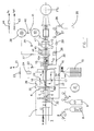
- the injection system of the present invention is formed of a supporting construction, not shown in the figure, to which a pneumatic propulsion system, a cryogenic device and a vacuum system are connected.
- the pneumatic system includes a pneumatic propulsion system 1 formed of a first stage 2, a second stage 4 and two valves 3 and 6 which will be described in more detail afterwards.
- the first valve 3 separates stage 2 from stage 4, the other valve 6 separates the propulsion system 1 from the launching barrel 7.
- the compression piston 5 or more pistons is placed.
- the feeding of said propulsion system 1 is provided by gas cylinders 8 through a set of valves and pressure reducers 9.
- the gases ejected by the propulsion system 1 flow through launching barrel 7 of cryogenic device, valve 10, diagnostic station D, and valve 10A into decompression chambers 11 and 12, from which the gases are evacuated through a vacuum system.
- the decompression chambers are separated from each other by valve 13, and a valve 14 separates chamber 12 from the machine using the pellet.
- the cryogenic device is formed of a Dewar flask 15 from which the fluid for refrigerating one or more copper flanges 18 is sucked through a special transferring pipe 16 which will be described afterwards.
- the flanges are placed within cryostat 17 and are welded to the launching barrel 7 so as to generate a cold point along the barrel at which the pellet will solidify.
- At the sides of flange 18 two electric resistances 19A and 19B limiting the cold zone are connected to barrel 7 in thermal contact therewith.
- the whole assembly is protected by a radiation screen 20 which is also cooled by the fluid conveyed then to a recovery line 21 provided with valves 22 and 23 and a differential pressure gage 24.
- the gas (isotopes of hydrogen) necessary to the construction of the pellet is supplied by a gas cylinder 25 through line 26 provided with a pressure reducing valve 27, a flowmeter 28, a pressure switch 29 and a valve 30.
- the gas is then sucked to the cold point by cryopumping.
- the vacuum system includes a rotating pump 31 which evacuates second stage 4, cryostat 17 and launching barrel 7 through valves 32, 33 and 34, respectively, the vacuum measurement being effected in the above cryostat by means of two vacuum gages 35 and 36.
- Decompression chambers 11 and 12 are evacuated through valves 37 and 38 by turbomolecular pump 39, valve 40 and rotating pump 42. Downstream of valve 40 the vacuum gage 41 is provided.
- the turbomolecular pump is provided with a water cooling circuit 43 and a gas nitrogen circuit 44 used in the stopping phase of the turbine.
- the vacuum is monitored by means of a pressure transducer 45 and two vacuum gages 46 and 47.
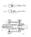
- Fig. 4 shows a preferred embodiment of valve 3. It includes a pressure-containing member or shutter 3a and a valve seat 3b separating first stage 2 from second stage 4.
- the shutter is pneumatically driven by high pressure gas through an inlet port 52 and a conduit 54 upstream of chamber 50. The gas flows along the walls of the shutter and fills first stage 2.
- shutter 3a is cylindrical and provided with a little shoulder 56 to start the stroke when the upstream chamber 50 is evacuated to the atmosphere through electrovalve 58 at one end of conduit 54.
- the high pressure in stage 2 acts on the section of the shutter and causes the latter to move very quickly backwards.
- Figs. 5a and 5b show a preferred embodiment of valve 6.
- the main feature of such valve is of assuring the separation between cryostat and propulsor with a good vacuum sealing, which is essential when cold components are processed with a very small volume in order to keep a good compression ratio and then a good performance of the propulsor.
- Such valve includes a body 61 in which the sliding seat of a slide 65 is formed, the latter being a blade provided with a small hole 66 and a slot 68 receiving a pin 70.
- the slot restricts the stroke of the slide which opens or closes the cross channel 72 connecting second stage 4 to launching barrel 7.
- the movement of the slide is controlled by a pneumatic actuator, not shown, which is rigidly connected to bracket 74.
- Fig. 6 shows a preferred embodiment of the transferring pipe 16.
- Pipe 16 allows the saturated vapours of He to be drawn at a temperature of about 4,2 K disregarding the amount of liquid contained in Dewar flask 15. It includes two branch pipes 16a and 16b which are inserted into Dewar flask 15 and cryostat 17, respectively.
- the pipe is insulated by a vacuum sheath, and its end which is intended for the suction of the cold gas from the Dewar flask is provided with four holes formed at an upper level than the height which can be reached by the liquid in the Dewar flask.
- the pipe may draw only the vapour which is cooled through the sheath 16c and flows in the inner coaxial pipe 16d to reach cryostat 17.
- Fig. 7 shows a preferred embodiment of the expansion or decompression chambers 11 and 12. These chambers are formed of two identic tanks connected in series with the interposition of valve 13.
- Pipe 82 extends axially and is provided with dynamic impedances formed by suitable shaping of inlet ports 84 and output nozzles 86.
- the decompression chamber system seeks to combine three criteria to separate the propelling gas from the pellet:
- valve 3 The quick closure of valve 3 and the relatively quick closure of valve 6 contribute to the reduction of the gas flow.
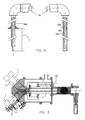
- a propulsion system provided with two pistons is schematically shown in Fig. 2b.
- the main compression piston 5 is placed downstream of a secondary piston 5a provided with a suitable hole.
- FIG. 3 An injector provided with several barrels is shown in Fig. 3 where there are four pneumatic propulsors 1 and four launching barrels 7.
- the completely automized operation of the system according to the invention is controlled by a programmable logic controller PLC, in which the operative sequence for the case of gaseous deuterium is stored, as follows.
- second stage 4 of propulsion system 1, cryostat 17 and launching barrel 7 are evacuated by rotating pump 31.
- a preliminary vacuum is established in decompression chambers 11 and 12 through rotating pump 42 and afterwards a hard vacuum is provided by turbomolecular pump 39.
- a hard vacuum is provided by turbomolecular pump 39.
- the cooling circuit of the cryogenic system is activated. As the temperature of cryostat 17 is reduced below 100 K, valve 33 is closed so that cryostat 17 remains under static vacuum conditions. The subsequent cooling causes the vacuum grade to improve by cryo-pumping.
- gaseous deuterium from gas cylinders 25 is allowed to flow into launching barrels 7.
- the flow of the gaseous deuterium is monitored, regulated and integrated in the time by suitable instruments, flowmeter 28, and pressure gage 29, so as to assure a constant pressure lower than that of the triple point of the gas in the barrel during the solidification of the pellet.
- the pellet is shot.
- valve 3 causing the propulsion system 1 to shoot the pellet is also opened.
- the produced pressure pulse accelerates the pellet along the launching barrel 7 and expels it from the latter so that it is allowed to pass through the diagnostic section D and the two decompression chambers 11 and 12 up to the centre of the plasma column.
- valve 3 soon after the shooting of pellet P is followed by the closure of valves 6, 10, 10A, 13 and 14 so as to restore the starting conditions and to produce a new pellet.
- second stage 4 launching barrel 7 and decompression chambers 11 and 12 are evacuated, and the transfer of the cooling fluid is stopped so that the cryostat is naturally heated to a temperature of about 20-25 K.
- the present invention suggests the use of a cryostat allowing the pellet to be solidified by a technique similar to that of the growth of the single crystals, as better illustrated afterwards.
- Figs. 9, 10a and 10b show a preferred but not restricted embodiment of a device which unlike that described previously is placed vertically.
- cryogenic pellet is not manufactured any longer directly “in situ", i.e. in the location from which it is then shot, but it is solidified in the location of Fig. 10b and then transferred to be shot to the location of Fig. 10a by a properly moved vacuum sealing system.
- a properly moved vacuum sealing system is schematically comprised of a body 94 supporting the launching barrel 7 and adapted to axially move and to rotate with respect to the fixed base 95, in which two seats are formed, a dead seat 97 and a seat connected to the propulsor through pipe 98.
- the operation is as follows: after the launching barrel 7 placed as shown in Fig. 10b is evacuated, a desired amount of reactant (for example deuterium) is supplied; the volume of the gas to be solidified is sufficiently small as to cause the pressure to be brought to a value grater than that of the triple point.
- a desired amount of reactant for example deuterium
- the volume of the gas to be solidified is sufficiently small as to cause the pressure to be brought to a value grater than that of the triple point.
- the temperature of the cryostat falls below the equilibrium value corresponding to the pressure in the barrels, the gas starts to liquefy and to be collected by gravity in chamber 90 at the lower end of barrel 7 corresponding to the cold point.
- the liquid starts then to solidify slowly under a thermal gradient which is suitably controlled by heater 100, for example an electric resistance, so as to simulate the typical conditions of the growth of the single crystals which is as free as possible from lattice imperfections and then provided presumably with better mechanical properties.
- heater 100 for example an electric resistance
- the pellet is carried to the location of Fig. 10a and then shot.
Landscapes
- Physics & Mathematics (AREA)
- Engineering & Computer Science (AREA)
- Plasma & Fusion (AREA)
- Optics & Photonics (AREA)
- Spectroscopy & Molecular Physics (AREA)
- Chemical & Material Sciences (AREA)
- Chemical Kinetics & Catalysis (AREA)
- General Engineering & Computer Science (AREA)
- High Energy & Nuclear Physics (AREA)
- Plasma Technology (AREA)
- Physical Or Chemical Processes And Apparatus (AREA)
Applications Claiming Priority (2)
| Application Number | Priority Date | Filing Date | Title |
|---|---|---|---|
| IT48151A IT1241992B (it) | 1990-07-17 | 1990-07-17 | Iniettore miniaturizzato ad alta velocita', ad una o piu' canne, di pellet criogenici, in particolare per l'utilizzo su macchine per la fusione nucleare controllata mediante confinamento magnetico del plasma. |
| IT4815190 | 1990-07-17 |
Publications (2)
| Publication Number | Publication Date |
|---|---|
| EP0467864A2 true EP0467864A2 (fr) | 1992-01-22 |
| EP0467864A3 EP0467864A3 (en) | 1992-07-29 |
Family
ID=11264860
Family Applications (1)
| Application Number | Title | Priority Date | Filing Date |
|---|---|---|---|
| EP19910830313 Withdrawn EP0467864A3 (en) | 1990-07-17 | 1991-07-16 | High rate, single or multi-barrel, miniaturized injection system of cryogenic pellets, in particular for use in machines for the controlled nuclear fusion by magnetic confinement of plasma |
Country Status (3)
| Country | Link |
|---|---|
| US (1) | US5406594A (fr) |
| EP (1) | EP0467864A3 (fr) |
| IT (1) | IT1241992B (fr) |
Cited By (1)
| Publication number | Priority date | Publication date | Assignee | Title |
|---|---|---|---|---|
| US7527768B2 (en) * | 2004-08-26 | 2009-05-05 | Musashi Engineering Inc. | Liquid dispenser with vacuum control |
Families Citing this family (4)
| Publication number | Priority date | Publication date | Assignee | Title |
|---|---|---|---|---|
| RU2229749C2 (ru) * | 2002-07-29 | 2004-05-27 | Федеральное государственное унитарное предприятие "Научно-исследовательский институт электрофизической аппаратуры им. Д.В. Ефремова" | Способ инжекции термоядерного топлива в вакуумную камеру термоядерного реактора |
| RU2242809C2 (ru) * | 2003-01-14 | 2004-12-20 | Богданов Игорь Глебович | Устройство для осуществления управляемой реакции термоядерного синтеза |
| RU2244357C2 (ru) * | 2003-01-17 | 2005-01-10 | Ванин Виктор Николаевич | Ядерный автомобильный двигатель |
| US10746477B2 (en) * | 2016-10-07 | 2020-08-18 | Toyota Motor Engineering & Manufacturing North America, Inc. | Systems and methods for degassing and charging phase-change thermal devices |
Family Cites Families (3)
| Publication number | Priority date | Publication date | Assignee | Title |
|---|---|---|---|---|
| DE1814888A1 (de) * | 1968-12-16 | 1970-07-16 | Inst Plasmaphysik Gmbh | Verfahren und Einrichtung zum Herstellen einer duennen,freitragenden Scheibe im Hochvakuum aus bei Raumtemperatur gasfoermigem Material,wie Wasserstoff |
| US3723246A (en) * | 1971-05-27 | 1973-03-27 | Atomic Energy Commission | Plasma production apparatus having droplet production means and laserpre-pulse means |
| DK556887D0 (da) * | 1987-10-23 | 1987-10-23 | Risoe Forskningscenter | Fremgangsmaade til fremstilling af en pille og injektor til injektion af saadan pille |
-
1990
- 1990-07-17 IT IT48151A patent/IT1241992B/it active IP Right Grant
-
1991
- 1991-07-16 EP EP19910830313 patent/EP0467864A3/en not_active Withdrawn
- 1991-07-17 US US07/731,062 patent/US5406594A/en not_active Expired - Fee Related
Cited By (1)
| Publication number | Priority date | Publication date | Assignee | Title |
|---|---|---|---|---|
| US7527768B2 (en) * | 2004-08-26 | 2009-05-05 | Musashi Engineering Inc. | Liquid dispenser with vacuum control |
Also Published As
| Publication number | Publication date |
|---|---|
| US5406594A (en) | 1995-04-11 |
| IT1241992B (it) | 1994-02-02 |
| IT9048151A1 (it) | 1992-01-17 |
| IT9048151A0 (it) | 1990-07-17 |
| EP0467864A3 (en) | 1992-07-29 |
Similar Documents
| Publication | Publication Date | Title |
|---|---|---|
| US4904441A (en) | Method of forming a pellet of condensed gas and a pellet injector for injecting the same into a reactor | |
| EP0089391B1 (fr) | Procédé et machine frigorifique à dilution pour un refroidissement à des températures en-dessous de 1 K | |
| US5406594A (en) | High rate, single or multi-barrel miniaturized injection system of cryogenic pellets, in particular for use in machines for the controlled nuclear fusion by magnetic confinement of plasma | |
| Milora et al. | Pneumatic hydrogen pellet injection system for the ISX tokamak | |
| US12180947B2 (en) | Compression device, installation, filling station and method using such a device | |
| US3455117A (en) | Method and apparatus for cooling and subcooling fluids such as hydrogen | |
| Dalesandro et al. | Results from sudden loss of vacuum on scaled superconducting radio frequency cryomodule experiment | |
| US20100122901A1 (en) | Vapor-Barrier Vacuum Isolation System | |
| JPH03181699A (ja) | 液相および気相を有する流体を貯蔵する貯蔵施設を充填する間圧力を所定限度以下に維持する方法およびそのための再凝縮施設 | |
| Bartenev et al. | Cryopumped, condensed hydrogen jet target for the National Accelerator Laboratory main accelerator | |
| US20050204752A1 (en) | Vacuum-insulating system and method for generating a high-level vacuum | |
| US3395546A (en) | Process for making semisolid cryogens | |
| US4860546A (en) | Vacuum system with molecular flow line | |
| Frattolillo et al. | High‐speed repeating hydrogen pellet injector for long‐pulse magnetic confinement fusion experiments | |
| US20190234672A1 (en) | Cryocooling system and method | |
| JPH08117644A (ja) | 極低温用ウルトラクリーンノズルとその製造方法 | |
| Kuteev et al. | Development of an ITER pellet fueling system in Russia | |
| JP3739697B2 (ja) | 融合装置用の固体水素アイソトープシェルを伴う不純物ペレットインジェクター | |
| JPH06221496A (ja) | 極低温液体注入方法および極低温液体注入装置 | |
| JP2002148377A (ja) | 重水素氷の連続生成・装填方法 | |
| Hemmerich et al. | The cryogenic diffusion pump and its implementation in a complete fusion reactor forevacuum system | |
| CN113983351A (zh) | 基于抽空减压结合压力交变的大规模氢浆制备装置及方法 | |
| RU2132577C1 (ru) | Двухступенчатый инжектор таблеток термоядерного топлива | |
| KR20250179616A (ko) | 헬륨 공급 장치 및 이를 이용한 헬륨 공급 방법 | |
| Foster et al. | A continuous cryogenic diffusion pump for fusion reactors |
Legal Events
| Date | Code | Title | Description |
|---|---|---|---|
| PUAI | Public reference made under article 153(3) epc to a published international application that has entered the european phase |
Free format text: ORIGINAL CODE: 0009012 |
|
| AK | Designated contracting states |
Kind code of ref document: A2 Designated state(s): AT BE CH DE DK ES FR GB GR LI LU NL SE |
|
| RAP1 | Party data changed (applicant data changed or rights of an application transferred) |
Owner name: ENTE PER LE NUOVE TECNOLOGIE, L'ENERGIA E L'AMBIEN |
|
| RAP1 | Party data changed (applicant data changed or rights of an application transferred) |
Owner name: ENTE PER LE NUOVE TECNOLOGIE, L'ENERGIA E L'AMBIEN |
|
| PUAL | Search report despatched |
Free format text: ORIGINAL CODE: 0009013 |
|
| AK | Designated contracting states |
Kind code of ref document: A3 Designated state(s): AT BE CH DE DK ES FR GB GR LI LU NL SE |
|
| 17P | Request for examination filed |
Effective date: 19930125 |
|
| 17Q | First examination report despatched |
Effective date: 19950125 |
|
| STAA | Information on the status of an ep patent application or granted ep patent |
Free format text: STATUS: THE APPLICATION IS DEEMED TO BE WITHDRAWN |
|
| 18D | Application deemed to be withdrawn |
Effective date: 19970201 |