EP0467865B1 - Apparatus for operating the switch blades of railway points - Google Patents
Apparatus for operating the switch blades of railway points Download PDFInfo
- Publication number
- EP0467865B1 EP0467865B1 EP91830315A EP91830315A EP0467865B1 EP 0467865 B1 EP0467865 B1 EP 0467865B1 EP 91830315 A EP91830315 A EP 91830315A EP 91830315 A EP91830315 A EP 91830315A EP 0467865 B1 EP0467865 B1 EP 0467865B1
- Authority
- EP
- European Patent Office
- Prior art keywords
- sliding block
- rollers
- shaft
- actuator
- seats
- Prior art date
- Legal status (The legal status is an assumption and is not a legal conclusion. Google has not performed a legal analysis and makes no representation as to the accuracy of the status listed.)
- Expired - Lifetime
Links
- 230000033001 locomotion Effects 0.000 claims description 16
- 230000003019 stabilising effect Effects 0.000 description 4
- 230000036961 partial effect Effects 0.000 description 3
- 230000002159 abnormal effect Effects 0.000 description 2
- 230000004075 alteration Effects 0.000 description 1
- 230000002547 anomalous effect Effects 0.000 description 1
- 230000006835 compression Effects 0.000 description 1
- 238000007906 compression Methods 0.000 description 1
- 230000007547 defect Effects 0.000 description 1
- 238000010586 diagram Methods 0.000 description 1
- 238000002955 isolation Methods 0.000 description 1
- 230000000670 limiting effect Effects 0.000 description 1
- 230000000452 restraining effect Effects 0.000 description 1
- 230000000717 retained effect Effects 0.000 description 1
- 230000002441 reversible effect Effects 0.000 description 1
- 230000011664 signaling Effects 0.000 description 1
- 239000003381 stabilizer Substances 0.000 description 1
Images






Classifications
-
- B—PERFORMING OPERATIONS; TRANSPORTING
- B61—RAILWAYS
- B61L—GUIDING RAILWAY TRAFFIC; ENSURING THE SAFETY OF RAILWAY TRAFFIC
- B61L5/00—Local operating mechanisms for points or track-mounted scotch-blocks; Visible or audible signals; Local operating mechanisms for visible or audible signals
- B61L5/10—Locking mechanisms for points; Means for indicating the setting of points
Definitions
- EP-A-0 289 978 discloses an apparatus for operating the switch blades of railway points having the features of the preamble of claim 1.
- the apparatus according to the present invention comprises furthermore means for detecting the correct position of the switch blades against the stock rails at the end of the switch stroke, according to the characterizing portion of claim 1.
- the sliding block has recesses with a vertical outward wall and an inclined inward wall; the shafts of the switch blades have passing seats; rollers can be received in said recesses and in said passing seats or in recesses of a fixed structure and in said passing seats, the rollers remaining in that case completely above said sliding block; and associated with said fixed structure are elastic means able to act on the rollers to prevent their escape from said recesses, and contacts to detect the correct position of the rollers.
- FIGs. 1-11 2 indicates one stock rail and 26 the other stock rail.
- the switch blade 4 can interact with the stock rail 2 and the switch blade 24 interacts with the switch blade 26.
- the switch blade 24 is fixed to a shaft or pull rod 22, at a thickened end of which it has a seat 22A for a roller 20.
- the switch blade 4 is fixed to a shaft or pull rod 6 which likewise forms a seat 6A for a roller 12.
- a fixed structure 14 forms two housings 14A and 14B, with which springs 8 and 18 are associated to exert a downward thrust. On the fixed structure 14 run two retaining pins 10 and 16 which are for restraining a trolley 34.
- the sliding block 36 indicates a sliding block that has two cavities 36A and 36B each having a vertical outward wall and an inclined inward wall; the rollers 12 and 20 are able to interact with the two cavities 36A and 36B.
- the sliding block 36 has a dihedral seat - on the side in the drawing (Fig. 2) - with which an elastic roller-type peg belonging to the trolley 34 interacts; able to interact with another dihedral seat - lower down in the drawing - on the sliding block 36, is an elastic roller-type peg 32 belonging to an actuator 30, which runs along fixed aide means 30A.
- 28 and 38 indicate elastic stabilisers for the switch blades at their end of travel.
- Electrical controls are provided to detect various conditions, among these being: contacts a and b for the position of the rollers 20 and 12 respectively when entering the housings 14B and 14A; contacts c and d to detect the presence at end-of-travel of the sliding block 36; contacts e and f to detect the ends of travel of the actuator 30.
- the actuator 30 leaves the position of Fig. 1 and, after releasing the trolley 34 by lifting the pin 16, engages the sliding block 36 with the peg 32; thus, through the roller 12 and the pull rod 6, the sliding block (Fig. 3) begins to move the switch blade 4; at the start of the translational movement, as the space R is cancelled out, that is as the overlap R is eliminated (Fig. 4), the roller 20 finds the cavity 36B and enters it owing to its own weight and the stressing of the spring 18, so that the sliding block 36 becomes fixed - by the roller 20 - to the pull rod 22, so triggering the pulling of the switch blade 24 as well.
- the released trolley 34 is pulled along with the sliding block 36 without braking its motion since it is engaged by its elastic roller in the dihedral seat at the side of the sliding block.
- the various electrical contacts C pick up the movement of the sliding block 36.
- the sliding block having overcome the pre-established load, cancels the space R1, that is eliminates the overlap R1, engages the roller 12, the pull rod 6 and the switch blade 4, allowing the system to come to the position of points forced open (Fig. 8).
- the combination of the sliding block 36 and the trolley 34 - with the dihedral seat of the sliding block 36 and the elastic roller-type peg of the trolley 34 - gives a profile that can recover the travel over pre-established limited values.
- the electrical controls d would indicate the "forcing open" of the points.
- Fig. 9 shows the trolley 34 disconnected.
- Fig. 10 shows an anomaly arising when the points are operated and the stock rail 2 is not found in the right position.
- the roller 12 is not compelled to come up, compressing the spring 8, does not achieve the throw-over, and the electrical contact b is not therefore activated.
- the electrical controls which will be affected by the successive events carried out at the end of the operation, are thus in a condition to indicate the anomaly. The system is therefore not point-locked.
- the actuator 30 In the case of a foreign body CE being interposed between the switch blade 4 and the stock rail 2 (Fig. 11), the actuator 30 starting from the condition of Fig. 4, disconnects itself, after putting out its maximum pulling load, from the sliding lock 36 and carries on to its end-of-travel without the limit switch d being previously affected. Since the operation has not been completed properly, the throwing over of the points, with the lifting of the roller 12, does not occur here either, and therefore in this case too the system is not point-locked, and the electrical controls indicate this condition.
- the elastic retaining pegs 28 and 38 have the function of stabilising the switch blades in position at the end of the operation by interacting with corresponding cavities formed, for example, in the shafts or pull rods 22 and 6.
- 102 and 126 indicate the two stock rails, with which the switch blades 104 and 124 respectively can interact alternately.
- Fixed to the switch blade 104 is a shaft 106 provided with a seat 106A for a roller 112; fixed to the switch blade 124 is a shaft 122 provided with a seat 122A for a roller 120.
- the fixed structure of the box comprises a part 114 and two components 154 each of which has two access seats 154A and 154B, into which rollers 150 and 151 respectively can be partially received.
- 136 indicates a sliding block that has two walls 136X defining a lower depression 136Y; in this depression 136Y a cavity 136Z is formed with a partial cylindrical surface.
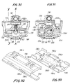
- the sliding block 136 On the top of the sliding block 136 are two symmetrical cavities 136A and 136B with inward lateral access wall. Underneath, at the sides of the cylindrically surfaced cavity 136Z are two seats 136D, and two outward walls 136C. 130 indicates the shaft or pull rod of an external actuator 131, intended to work the movements of the switch blades. Fixed to the shaft or pull rod 130 are two lateral forks 152 and 153, capable of movements inside the depression 136Y of the sliding block 136, between the walls 136X. On the shaft 130, two cups 155 and 156 are slidably mounted facing each other, and contained between them is a compression spring 158 that tends to hold them apart; the two cups are partially housed within the cavity 136Z.
- each of the cups 155 and 156 Fixed to each of the cups 155 and 156 is a pair of wings 155A and 156A respectively, being symmetrical about the corresponding cup and forming passing seats for the abovementioned rollers 150 and 151 respectively. Interacting with the shaft 130 is, among other things, an elastic peg 138 to stabilise the position of the shaft.
- the fixed part 114 has two seats 114A and 114B for receiving the rollers 112 and 120; associated with said seats 114A and 114B are push springs 108 and 118 respectively for the rollers 112 and 120.
- the actuator 131 for the shaft 130 comprises a carriage pulling system 162 worked by a motor 164 through a pinion 164A and a rack 162A; the carriage 162 has an elastic pin 162B which interacts with a seat 130A in the pull rod 130.
- 170A and 170B indicate two limit switches for the carriage system 162.
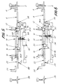
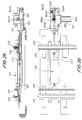
- Figs 25 and 26 show the end of travel to the right when viewing the drawing: the elastic peg 162B of the carriage pulling system 162 has disengaged itself from the seat 130A in the pull rod 130; when the carriage 162 comes into contact with the switch 170A, the motor 164 is stopped and prepared for the reverse operation.
- Figs 27 and 28 show an intermediate position in the stage of pulling to the left when viewing the drawing; the carriage 162 has engaged with the peg 162A in the seat 130A of the shaft or pull rod 130, as a result of which the pulling system moves the shaft 130 in the direction f130; this movement will end when the switch blade, by reaching the end-of-travel position, compels the unit 162, 162A to disconnect from the shaft 130 and to carry on until it works the switch 170B which - in the same way as described above for the switch 170A - will cut off the motor 164.
- the shaft or pull rod 130 leaves the position of Fig.12 and, moving in the direction of the arrow f130 of Fig.13, pulls the forks 152 and 153 - which are symmetrical with each other and fixed to the shaft - thereby enabling: on the one hand, the rollers 150 which in the position of Fig.12 were retained by the fork 152 in the seats 154A of the components 154 fixed to the structure of the box to be released; and on the other hand to engage, with the fork 153, the rollers 151 contained in the corresponding eyelets of the wings 155A of the cup 155.
- Said rollers 151 (Fig.14) transmit the movement of the shaft 130, through the tooth of the shoulder 136C, to the sliding block or drawer 136, which thereby moves in the direction f130, allowing movement by the cup 156 and rollers 150 as well, without loading the spring 158.
- the movement of the sliding block 136 causes, through the roller 112 and the pull rod 106, the switch blade 104 to move and at the same time cancels the offset R3, that is removes the overlap R3 (Fig.13) between the roller 120 and the seat 136B and allows the roller 120 to slip into the seat 136B of the sliding block 136, thereafter enabling the sliding block 136 also to pull the pull rod 122 and the switch blade 124 (Fig. 15).
- rollers 151 enter the seats 154B of the fixed parts 154 and are trapped by the fork 153.
- the sliding block or drawer 136 is held in position by the cup 155 which in turn is trapped by the rollers 151 on the fixed part of the box, comprising the components 154.
- the elastic peg stabilising system 138 holds the pull rod 130 in the end-of-travel position (Fig.17) opposite to that illustrated in Fig. 1.
- Figs 18 and 19 show the stage in which the points are forced apart. If the switch blade 124 is forced towards the stock rail 126 (as indicated by the arrow fT in Fig. 18) the roller 120 transmits the force to the sliding block 136 which, by moving, after overcoming the resistance of the elastic stabilising peg 138 of the pull rod 130, compresses the spring 158 (Figs 18 and 19), because the cup 155 is held in position by the rollers 151 engaged in the seats 154B of the fixed components 154.
- Fig. 20 shows an anomaly arising when the points are operated and the stock rail 102 is not found in the right position.
- the roller 112 is not compelled to come up into the seat 114A compressing the spring 108, and does not achieve the throw-over.
- the pull rod 106 will be stopped against the fixed part of the box 154 at the point 106B (Fig.20) preventing the sliding block or drawer 136 from continuing its travel.
- Fig. 21 shows the interposition of a foreign body CE between the switch blade 104 and the stock rail 102.
- the pulling system of the pull rod 130 actuator disconnects itself as already stated, and disconnects the motor from the pull rod.
- Suitable electrical contacts will determine whether the sliding block 136 has reached its end of travel, thereby signalling normal functioning, point-forcing and any abnormal cases as described above.
- An example of possible limit switches is indicated by fc ; these limit switches fc interact with the sliding block 136 at the end of its movement in one direction or the other.
- the spring 158 may be replaced by a rigid distance piece, for example tubular, to avoid the possibility of a mutual elastic approach between the two cups 155 and 156.
Landscapes
- Engineering & Computer Science (AREA)
- Mechanical Engineering (AREA)
- Train Traffic Observation, Control, And Security (AREA)
- Push-Button Switches (AREA)
- Displays For Variable Information Using Movable Means (AREA)
- Power-Operated Mechanisms For Wings (AREA)
- Road Repair (AREA)
- Toys (AREA)
- Handcart (AREA)
- Transmission Devices (AREA)
- Mechanisms For Operating Contacts (AREA)
- Tumbler Switches (AREA)
Applications Claiming Priority (4)
| Application Number | Priority Date | Filing Date | Title |
|---|---|---|---|
| IT944990 | 1990-07-19 | ||
| IT9449A IT1241757B (it) | 1990-07-19 | 1990-07-19 | Attrezzatura per la manovra degli aghi di uno scambio ferroviario |
| IT910008 | 1991-01-10 | ||
| ITFI910008A IT1246656B (it) | 1991-01-10 | 1991-01-10 | Attrezzatura per la manovra degli aghi di uno scambio ferroviario |
Publications (2)
| Publication Number | Publication Date |
|---|---|
| EP0467865A1 EP0467865A1 (en) | 1992-01-22 |
| EP0467865B1 true EP0467865B1 (en) | 1994-10-05 |
Family
ID=26326220
Family Applications (1)
| Application Number | Title | Priority Date | Filing Date |
|---|---|---|---|
| EP91830315A Expired - Lifetime EP0467865B1 (en) | 1990-07-19 | 1991-07-18 | Apparatus for operating the switch blades of railway points |
Country Status (5)
| Country | Link |
|---|---|
| EP (1) | EP0467865B1 (da) |
| AT (1) | ATE112528T1 (da) |
| DE (1) | DE69104431T2 (da) |
| DK (1) | DK0467865T3 (da) |
| ES (1) | ES2062745T3 (da) |
Families Citing this family (18)
| Publication number | Priority date | Publication date | Assignee | Title |
|---|---|---|---|---|
| AT136U1 (de) * | 1991-12-19 | 1995-03-27 | Alcatel Austria Ag | Vorrichtung zur endlagenpruefung von weichenzungen |
| SI9300651A (en) * | 1992-12-17 | 1994-06-30 | Voest Alpine Eisenbahnsysteme | Device for bolding movable parts of railway switches |
| SE506183C2 (sv) * | 1993-05-27 | 1997-11-17 | Abb Daimler Benz Transp | Anordning vid järnvägsspår för omläggning av spårväxel |
| FR2741365B1 (fr) * | 1995-11-22 | 1997-12-26 | Gec Alsthom Transport Sa | Dispositif de verrouillage d'une lame d'aiguille d'un aiguillage, dispositif de manoeuvre et de verrouillage d'une lame d'aiguille, procede de mise en place d'un tel dispositif |
| DE29709420U1 (de) * | 1997-05-30 | 1998-10-01 | Hanning & Kahl GmbH & Co., 33813 Oerlinghausen | Vorrichtung zum Verriegeln von beweglichen Weichenteilen |
| AT406038B (de) * | 1997-12-17 | 2000-01-25 | Vae Ag | Einrichtung zum unterstützen der verschiebebewegung und zum elastischen verriegeln von beweglichen weichenteilen |
| RU2181678C2 (ru) * | 1998-12-23 | 2002-04-27 | Российский государственный открытый технический университет путей сообщения | Винтовой стрелочный электропривод с внутренним замыканием шибера, взрезной, для работы с внешними замыкателями остряков стрелки и подвижных сердечников крестовин |
| EP1018461A1 (de) * | 1999-01-04 | 2000-07-12 | Siegfried Pütz | Weichenantriebsvorrichtung |
| US6164602A (en) * | 1999-02-17 | 2000-12-26 | Abc Rail Products Corporation | Railroad frog assembly with multi-position holdback |
| AU4384699A (en) * | 1999-06-01 | 2000-12-18 | Gabor Horvath | Driving gear for points |
| NL1016157C2 (nl) * | 2000-09-12 | 2002-03-13 | Nma Railway Signalling B V | Krachtbegrenzer. |
| ITFI20010028U1 (it) * | 2001-03-27 | 2002-09-27 | Siliani Harmon S P A | Cassa di manovra per scambi |
| DE10212979B4 (de) * | 2002-03-19 | 2005-11-24 | Siemens Ag | Endlagenprüfvorrichtung für eine Weiche |
| AT411350B (de) * | 2002-08-13 | 2003-12-29 | Vae Eisenbahnsysteme Gmbh | Weichenantrieb für bewegliche herze |
| ITFI20030296A1 (it) * | 2003-11-19 | 2005-05-20 | Ge Transp Systems S P A | Cassa di manovra per scambi ferroviari |
| US20050178929A1 (en) * | 2004-02-17 | 2005-08-18 | General Electric Company | Switch machine with improved switch point connectors |
| CZ16068U1 (cs) * | 2005-11-08 | 2005-12-05 | DT výhybkárna a mostárna a. s. | Zámkový mechanismus |
| ES2495090A1 (es) * | 2013-03-15 | 2014-09-16 | Talleres Alegría S.A. | Dispositivo de retención para elementos móviles en aparatos ferroviarios |
Family Cites Families (1)
| Publication number | Priority date | Publication date | Assignee | Title |
|---|---|---|---|---|
| FR2614908B1 (fr) * | 1987-05-05 | 1989-06-16 | Alsthom | Dispositif de manoeuvre d'un aiguillage |
-
1991
- 1991-07-18 DK DK91830315.7T patent/DK0467865T3/da active
- 1991-07-18 AT AT91830315T patent/ATE112528T1/de not_active IP Right Cessation
- 1991-07-18 EP EP91830315A patent/EP0467865B1/en not_active Expired - Lifetime
- 1991-07-18 DE DE69104431T patent/DE69104431T2/de not_active Expired - Lifetime
- 1991-07-18 ES ES91830315T patent/ES2062745T3/es not_active Expired - Lifetime
Also Published As
| Publication number | Publication date |
|---|---|
| ES2062745T3 (es) | 1994-12-16 |
| DE69104431T2 (de) | 1995-04-20 |
| EP0467865A1 (en) | 1992-01-22 |
| DE69104431D1 (de) | 1994-11-10 |
| DK0467865T3 (da) | 1994-10-31 |
| ATE112528T1 (de) | 1994-10-15 |
Similar Documents
| Publication | Publication Date | Title |
|---|---|---|
| EP0467865B1 (en) | Apparatus for operating the switch blades of railway points | |
| EP2941399B1 (en) | Elevator and means for forming a safety space | |
| KR100421240B1 (ko) | 철도, 전차궤도 전철기 또는 유사장치용 스위치 박스 | |
| US6691958B2 (en) | Switch machine | |
| RU2714363C2 (ru) | Узел оси железнодорожного транспортного средства | |
| JPH0741839B2 (ja) | 転轍器 | |
| CN106185574B (zh) | 一种电梯安全触板防夹机构 | |
| DE102019109634A1 (de) | Sich selbsttätig fortbewegender Saugroboter sowie System aus einem sich selbsttätig fortbewegenden Saugroboter und einem externen Saugreinigungsgerät | |
| CN102820164A (zh) | 用于真空断路器的位置检测器 | |
| GB2139792A (en) | A safety device for mechanical cabinets and similar equipment or machines | |
| US3446365A (en) | Vehicle coupling | |
| EP0448017B1 (en) | Device and procedure for opening the doors of an elevator | |
| GB2101003A (en) | Filter press plate-separating mechanism | |
| CN216686990U (zh) | 防错层电气系统以及包括该系统的电梯 | |
| CN216153781U (zh) | 一种电空转辙机用智能机械锁闭系统 | |
| KR100616017B1 (ko) | 덤웨이터의 카 고정장치 | |
| JP3785694B2 (ja) | シャッターの障害物感知装置 | |
| SU1008048A1 (ru) | Устройство дл автоматического расцеплени вагонов | |
| JP2018034977A (ja) | エレベーターのかご上安全スイッチ装置 | |
| IT9009449A1 (it) | Attrezzatura per la manovra degli aghi di uno scambio ferroviario | |
| EP3147174B1 (en) | Apparatus for operating a switch of a railway track and associated switch | |
| CN111980493A (zh) | 电磁锁 | |
| SU544578A1 (ru) | Напольное устройство дл автоматического расцеплени железнодорожного подвижного состава | |
| JP7185859B1 (ja) | エレベータの点検補助装置 | |
| CN116252669B (zh) | 电池锁止机构、车身支架及电动汽车 |
Legal Events
| Date | Code | Title | Description |
|---|---|---|---|
| PUAI | Public reference made under article 153(3) epc to a published international application that has entered the european phase |
Free format text: ORIGINAL CODE: 0009012 |
|
| AK | Designated contracting states |
Kind code of ref document: A1 Designated state(s): AT BE CH DE DK ES FR GB GR LI LU NL SE |
|
| 17P | Request for examination filed |
Effective date: 19920123 |
|
| 17Q | First examination report despatched |
Effective date: 19930519 |
|
| GRAA | (expected) grant |
Free format text: ORIGINAL CODE: 0009210 |
|
| AK | Designated contracting states |
Kind code of ref document: B1 Designated state(s): AT BE CH DE DK ES FR GB GR LI LU NL SE |
|
| REF | Corresponds to: |
Ref document number: 112528 Country of ref document: AT Date of ref document: 19941015 Kind code of ref document: T |
|
| REG | Reference to a national code |
Ref country code: DK Ref legal event code: T3 |
|
| REF | Corresponds to: |
Ref document number: 69104431 Country of ref document: DE Date of ref document: 19941110 |
|
| REG | Reference to a national code |
Ref country code: ES Ref legal event code: FG2A Ref document number: 2062745 Country of ref document: ES Kind code of ref document: T3 |
|
| REG | Reference to a national code |
Ref country code: GR Ref legal event code: FG4A Free format text: 3013559 |
|
| EAL | Se: european patent in force in sweden |
Ref document number: 91830315.7 |
|
| ET | Fr: translation filed | ||
| PLBE | No opposition filed within time limit |
Free format text: ORIGINAL CODE: 0009261 |
|
| STAA | Information on the status of an ep patent application or granted ep patent |
Free format text: STATUS: NO OPPOSITION FILED WITHIN TIME LIMIT |
|
| 26N | No opposition filed | ||
| REG | Reference to a national code |
Ref country code: GB Ref legal event code: IF02 |
|
| PGFP | Annual fee paid to national office [announced via postgrant information from national office to epo] |
Ref country code: ES Payment date: 20100615 Year of fee payment: 20 |
|
| PGFP | Annual fee paid to national office [announced via postgrant information from national office to epo] |
Ref country code: NL Payment date: 20100715 Year of fee payment: 20 |
|
| PGFP | Annual fee paid to national office [announced via postgrant information from national office to epo] |
Ref country code: LU Payment date: 20100702 Year of fee payment: 20 Ref country code: AT Payment date: 20100729 Year of fee payment: 20 Ref country code: DE Payment date: 20100921 Year of fee payment: 20 Ref country code: FR Payment date: 20100713 Year of fee payment: 20 Ref country code: GB Payment date: 20100617 Year of fee payment: 20 Ref country code: SE Payment date: 20100719 Year of fee payment: 20 |
|
| PGFP | Annual fee paid to national office [announced via postgrant information from national office to epo] |
Ref country code: GR Payment date: 20100609 Year of fee payment: 20 |
|
| PGFP | Annual fee paid to national office [announced via postgrant information from national office to epo] |
Ref country code: DK Payment date: 20100703 Year of fee payment: 20 |
|
| PGFP | Annual fee paid to national office [announced via postgrant information from national office to epo] |
Ref country code: CH Payment date: 20101027 Year of fee payment: 20 Ref country code: BE Payment date: 20100709 Year of fee payment: 20 |
|
| REG | Reference to a national code |
Ref country code: DE Ref legal event code: R071 Ref document number: 69104431 Country of ref document: DE |
|
| REG | Reference to a national code |
Ref country code: DE Ref legal event code: R071 Ref document number: 69104431 Country of ref document: DE |
|
| REG | Reference to a national code |
Ref country code: NL Ref legal event code: V4 Effective date: 20110718 |
|
| REG | Reference to a national code |
Ref country code: CH Ref legal event code: PL |
|
| BE20 | Be: patent expired |
Owner name: ANGIOLO *SILIANI S.P.A. Effective date: 20110718 |
|
| REG | Reference to a national code |
Ref country code: DK Ref legal event code: EUP |
|
| REG | Reference to a national code |
Ref country code: GB Ref legal event code: PE20 Expiry date: 20110717 |
|
| REG | Reference to a national code |
Ref country code: SE Ref legal event code: EUG |
|
| PG25 | Lapsed in a contracting state [announced via postgrant information from national office to epo] |
Ref country code: GB Free format text: LAPSE BECAUSE OF EXPIRATION OF PROTECTION Effective date: 20110717 |
|
| PG25 | Lapsed in a contracting state [announced via postgrant information from national office to epo] |
Ref country code: NL Free format text: LAPSE BECAUSE OF EXPIRATION OF PROTECTION Effective date: 20110718 |
|
| PG25 | Lapsed in a contracting state [announced via postgrant information from national office to epo] |
Ref country code: DE Free format text: LAPSE BECAUSE OF EXPIRATION OF PROTECTION Effective date: 20110719 |
|
| REG | Reference to a national code |
Ref country code: ES Ref legal event code: FD2A Effective date: 20130722 |